brake SKODA ROOMSTER 2013 1.G Service Manual
[x] Cancel search | Manufacturer: SKODA, Model Year: 2013, Model line: ROOMSTER, Model: SKODA ROOMSTER 2013 1.GPages: 219, PDF Size: 13.83 MB
Page 188 of 219
Breakdown kitFig. 148
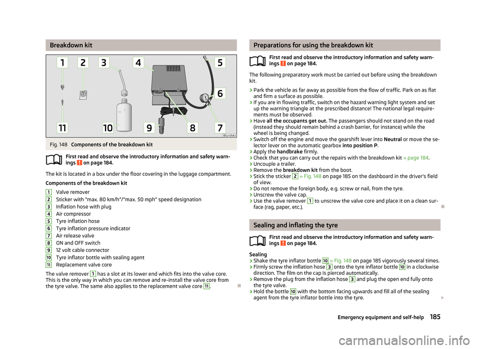
Components of the breakdown kit
First read and observe the introductory information and safety warn-
ings
on page 184.
The kit is located in a box under the floor covering in the luggage compartment.
Components of the breakdown kit Valve remover
Sticker with “max. 80 km/h”/“max. 50 mph” speed designation
Inflation hose with plug
Air compressor
Tyre inflation hose
Tyre inflation pressure indicator
Air release valve
ON and OFF switch
12 volt cable connector
Tyre inflator bottle with sealing agent
Replacement valve core
The valve remover
1
has a slot at its lower end which fits into the valve core.
This is the only way in which you can remove and re-install the valve core from
the tyre valve. The same also applies to the replacement valve core
11
.
1234567891011Preparations for using the breakdown kit
First read and observe the introductory information and safety warn-
ings
on page 184.
The following preparatory work must be carried out before using the breakdown
kit.
›
Park the vehicle as far away as possible from the flow of traffic. Park on as flat and firm a surface as possible.
›
If you are in flowing traffic, switch on the hazard warning light system and setup the warning triangle at the prescribed distance! The national legal require-
ments must be observed.
›
Have all the occupants get out. The passengers should not stand on the road
(instead they should remain behind a crash barrier, for instance) while the wheel is being changed.
›
Switch off the engine and move the gearshift lever into Neutral or move the se-
lector lever on the automatic gearbox into position P.
›
Apply the handbrake firmly.
›
Check that you can carry out the repairs with the breakdown kit » page 184.
›
Uncouple a trailer.
›
Remove the breakdown kit from the boot.
›
Stick the sticker
2
» Fig. 148 on page 185 on the dashboard in the driver's field
of view.
›
Do not remove the foreign body, e.g. screw or nail, from the tyre.
›
Unscrew the valve cap.
›
Use the valve remover
1
to unscrew the valve core and place it on a clean sur-
face (rag, paper, etc.).
Sealing and inflating the tyre
First read and observe the introductory information and safety warn-
ings
on page 184.
Sealing
›
Shake the tyre inflator bottle
10
» Fig. 148 on page 185 vigorously several times.
›
Firmly screw the inflation hose
3
onto the tyre inflator bottle
10
in a clockwise
direction. The film on the cap is pierced automatically.
›
Remove the plug from the inflation hose
3
and plug the open end fully onto
the tyre valve.
›
Hold the bottle
10
with the bottom facing upwards and fill all of the sealing
agent from the tyre inflator bottle into the tyre.
185Emergency equipment and self-help
Page 191 of 219
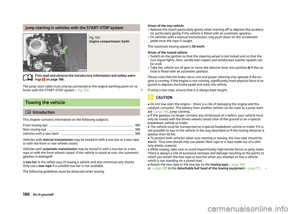
Jump-starting in vehicles with the START-STOP systemFig. 150
Engine compartment: Earth
First read and observe the introductory information and safety warn-ings on page 186.
The jump-start cable must only be connected to the engine earthing point on ve-
hicles with the START-STOP system » Fig. 150.
Towing the vehicle
Introduction
This chapter contains information on the following subjects:
Front towing eye
189
Rear towing eye
189
Vehicles with a tow hitch
189
Vehicles with manual transmission may be towed in with a tow bar or a tow rope
or with the front or rear wheels raised.
Vehicles with automatic transmission may be towed in with a tow bar or a tow
rope or with the front wheels raised. If the vehicle is raised at rear, the automatic
gearbox is damaged!
A tow bar is the safest way of towing a vehicle and also minimises any shocks.
Only use a tow rope if a suitable tow bar is not available.
The following guidelines must be observed when towing.
Driver of the tow vehicle›Release the clutch particularly gently when starting off or depress the accelera-
tor particularly gently if the vehicle is fitted with an automatic gearbox.›
On vehicles with a manual transmission, only push down on the accelerator pedal once the rope is taught.
The maximum towing speed is 50 km/h.
Driver of the towed vehicle
›
Switch on the ignition so that the steering wheel is not locked and so that the turn signal lights, horn, windscreen wipers and windscreen washer system can
be used.
›
Take the vehicle out of gear or move the selector lever into position N if the ve-
hicle is fitted with an automatic gearbox.
Please note that the brake servo unit and power steering only operate if the en-
gine is running. If the engine is not running, significantly more physical force is re-
quired to depress the brake pedal and steer the vehicle.
If using a tow rope, ensure that it is always kept taught.
CAUTION
■ Do not tow start the engine – there is a risk of damaging the engine and the
catalytic converter. The battery from another vehicle can be used as a jump-start
aid » page 186 , Jump-starting .■
If the gearbox no longer contains any oil because of a defect, your vehicle must
only be towed with the driven wheels raised clear of the ground or on a special
breakdown vehicle or trailer.
■
The vehicle must be transported on a special breakdown vehicle or trailer if it is
not possible to tow in the vehicle in the way described or if the towing distance is greater than 50 km.
■
To protect both vehicles when tow-starting or towing, the tow rope should be
elastic. Thus one should only use plastic fibre rope or a rope made out of a simi-
larly elastic material.
■
While towing, take care to avoid impermissibly high tensile forces or jerky loads.
There is always a risk of excessive stresses and damage resulting at the points to
which you attach the tow rope or tow bar when you attempt to tow a vehicle
which is not standing on a paved road.
■
Attach the tow rope or the tow bar to the towing eyes » page 189
or » page 189 to the detachable ball head of the towing equipment » page 117 .
188Do-it-yourself
Page 195 of 219
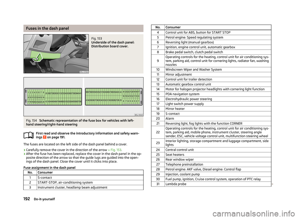
Fuses in the dash panelFig. 153
Underside of the dash panel:
Distribution board cover.
Fig. 154
Schematic representation of the fuse box for vehicles with left-
hand steering/right-hand steering
First read and observe the introductory information and safety warn-
ings
on page 191.
The fuses are located on the left side of the dash panel behind a cover.
› Carefully remove the cover in the direction of the arrow
» Fig. 153.
› After the fuse has been replaced, replace the cover in the dash panel in the op-
posite direction of the arrow so that the guide lugs are guided into the open- ings of the dash panel. Close the cover until it clicks into place.
Fuse assignment in the dash panel
No.Consumer1S-contact2START-STOP, air-conditioning system3Instrument cluster, headlamp beam adjustmentNo.Consumer4Control unit for ABS, button for START STOP5Petrol engine: Speed regulating system6Reversing light (manual gearbox)7Ignition, engine control unit, automatic gearbox8Brake pedal switch, clutch pedal switch9Operating controls for the heating, control unit for air conditioning sys-
tem, parking aid, control unit for cornering lights, radiator fan, washing nozzles10Windscreen Wiper and Washer System11Mirror adjustment12Control unit for trailer detection13Automatic gearbox control unit14Motor for halogen projector headlights with cornering light function15PDA navigation system16Electrohydraulic power steering17Light switch power supply18Mirror heater19S-contact20Alarm21Reversing light, fog lights with the function CORNER22Operating controls for the heating, control unit for air conditioning sys-
tem, parking aid, mobile phone, instrument cluster, steering angle
sender, ESC, vehicle voltage control unit, multifunction steering wheel23Interior lighting, storage compartment and luggage compartment, side
lights24Central control unit25Seat heaters26Rear window wiper27Telephone preinstallation28Petrol engine: AKF valve, Diesel engine: Control flap29Injection, coolant pump30Fuel pump, ignition, Cruise control system, operation of PTC relay31Lambda probe 192Do-it-yourself
Page 196 of 219
No.Consumer32High pressure fuel pump, pressure valve33Engine control unit34Engine control unit, vacuum pump35Daytime running lights/radio for vehicles with START-STOP36Main beam37Rear fog light, DC/DC converter START-STOP38Fog lights39Air blower for heating40-41Not assigned42Rear window heater43Horn44Windscreen wipers45Central control unit for convenience system46Engine control unit, fuel pump47Cigarette lighter, power socket in the luggage compartment48ABS, START-STOP (DC/DC) converter ESP49Turn signal lights, brake lights50START-STOP (DC/DC) transformer, radio51Electrical power window (front and rear) - left side52Electrical power window (front and rear) - right side53Parking light = left side, electrical sliding/tilting roof54START-STOP (instrument cluster), alarm55Automatic gearbox control unit56Headlight cleaning system, parking light - right side57Left low beam, headlight range adjustment58Low beam on the right
Fuses in the engine compartmentFig. 155
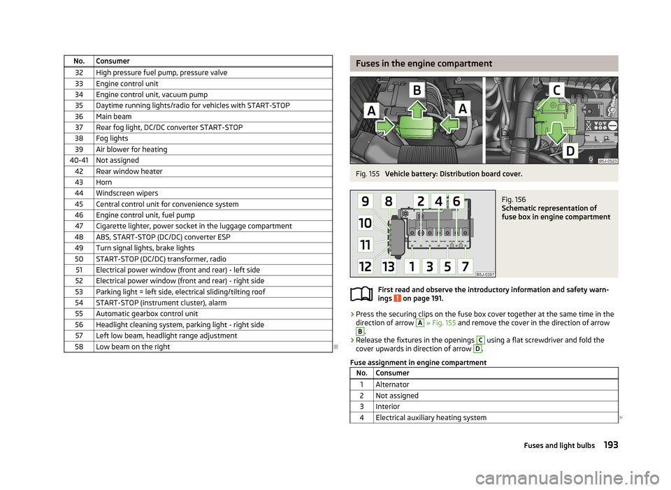
Vehicle battery: Distribution board cover.
Fig. 156
Schematic representation of
fuse box in engine compartment
First read and observe the introductory information and safety warn-
ings on page 191.
› Press the securing clips on the fuse box cover together at the same time in the
direction of arrow
A
» Fig. 155 and remove the cover in the direction of arrow
B
.
› Release the fixtures in the openings
C
using a flat screwdriver and fold the
cover upwards in direction of arrow
D
.
Fuse assignment in engine compartment
No.Consumer1Alternator2Not assigned3Interior4Electrical auxiliary heating system 193Fuses and light bulbs
Page 201 of 219
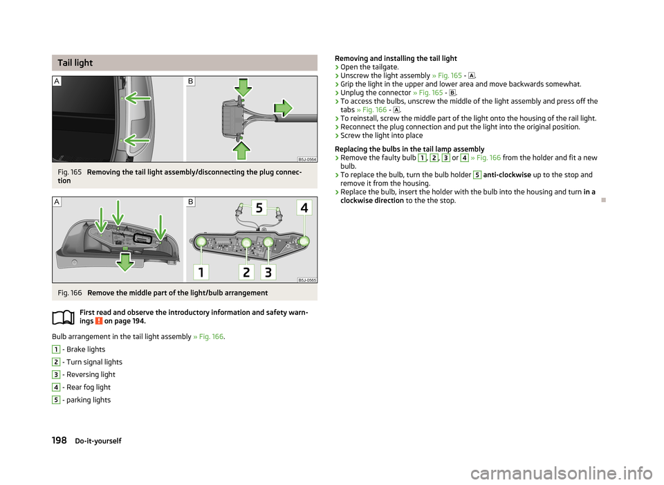
Tail lightFig. 165
Removing the tail light assembly/disconnecting the plug connec-
tion
Fig. 166
Remove the middle part of the light/bulb arrangement
First read and observe the introductory information and safety warn- ings
on page 194.
Bulb arrangement in the tail light assembly » Fig. 166.
1
- Brake lights
2
- Turn signal lights
3
- Reversing light
4
- Rear fog light
5
- parking lights
Removing and installing the tail light›Open the tailgate.›
Unscrew the light assembly » Fig. 165 - .
›
Grip the light in the upper and lower area and move backwards somewhat.
›
Unplug the connector » Fig. 165 - .
›
To access the bulbs, unscrew the middle of the light assembly and press off the
tabs » Fig. 166 - .
›
To reinstall, screw the middle part of the light onto the housing of the rail light.
›
Reconnect the plug connection and put the light into the original position.
›
Screw the light into place
Replacing the bulbs in the tail lamp assembly
›
Remove the faulty bulb
1
,
2
,
3
or
4
» Fig. 166 from the holder and fit a new
bulb.
›
To replace the bulb, turn the bulb holder
5
anti-clockwise up to the stop and
remove it from the housing.
›
Replace the bulb, insert the holder with the bulb into the housing and turn in a
clockwise direction to the the stop.
198Do-it-yourself
Page 205 of 219
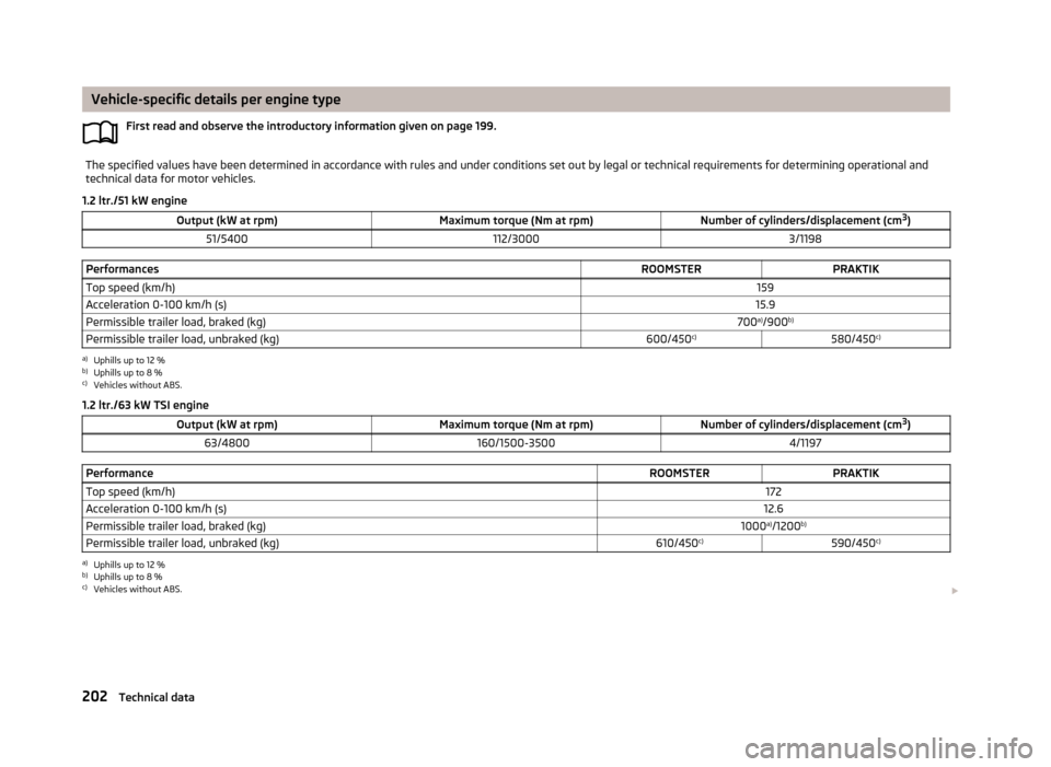
Vehicle-specific details per engine typeFirst read and observe the introductory information given on page 199.The specified values have been determined in accordance with rules and under conditions set out by legal or technical requirements for determining operational and
technical data for motor vehicles.
1.2 ltr./51 kW engine
Output (kW at rpm)Maximum torque (Nm at rpm)Number of cylinders/displacement (cm 3
)51/5400112/30003/1198PerformancesROOMSTERPRAKTIKTop speed (km/h)159Acceleration 0-100 km/h (s)15.9Permissible trailer load, braked (kg)700 a)
/900 b)Permissible trailer load, unbraked (kg)600/450 c)580/450c)a)
Uphills up to 12 %
b)
Uphills up to 8 %
c)
Vehicles without ABS.
1.2 ltr./63 kW TSI engine
Output (kW at rpm)Maximum torque (Nm at rpm)Number of cylinders/displacement (cm 3
)63/4800160/1500-35004/1197PerformanceROOMSTERPRAKTIKTop speed (km/h)172Acceleration 0-100 km/h (s)12.6Permissible trailer load, braked (kg)1000 a)
/1200 b)Permissible trailer load, unbraked (kg)610/450 c)590/450 c)a)
Uphills up to 12 %
b)
Uphills up to 8 %
c)
Vehicles without ABS.
202Technical data
Page 206 of 219
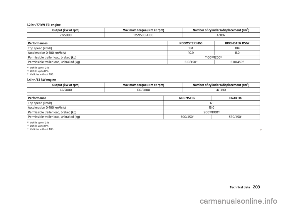
1.2 ltr./77 kW TSI engineOutput (kW at rpm)Maximum torque (Nm at rpm)Number of cylinders/displacement (cm3
)77/5000175/1500-41004/1197PerformancesROOMSTER MG5ROOMSTER DSG7Top speed (km/h)184184Acceleration 0-100 km/h (s)10.911.0Permissible trailer load, braked (kg)1100 a)
/1200 b)Permissible trailer load, unbraked (kg)610/450 c)630/450 c)a)
Uphills up to 12 %
b)
Uphills up to 8 %
c)
Vehicles without ABS.
1.4 ltr./63 kW engine
Output (kW at rpm)Maximum torque (Nm at rpm)Number of cylinders/displacement (cm 3
)63/5000132/38004/1390PerformanceROOMSTERPRAKTIKTop speed (km/h)171Acceleration 0-100 km/h (s)13.0Permissible trailer load, braked (kg)900 a)
/1100 b)Permissible trailer load, unbraked (kg)600/450 c)580/450c)a)
Uphills up to 12 %
b)
Uphills up to 8 %
c)
Vehicles without ABS.
203Technical data
Page 207 of 219
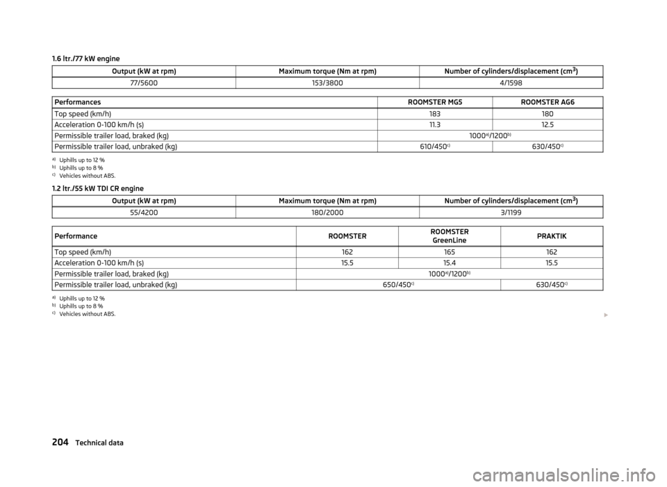
1.6 ltr./77 kW engineOutput (kW at rpm)Maximum torque (Nm at rpm)Number of cylinders/displacement (cm3
)77/5600153/38004/1598PerformancesROOMSTER MG5ROOMSTER AG6Top speed (km/h)183180Acceleration 0-100 km/h (s)11.312.5Permissible trailer load, braked (kg)1000 a)
/1200 b)Permissible trailer load, unbraked (kg)610/450 c)630/450 c)a)
Uphills up to 12 %
b)
Uphills up to 8 %
c)
Vehicles without ABS.
1.2 ltr./55 kW TDI CR engine
Output (kW at rpm)Maximum torque (Nm at rpm)Number of cylinders/displacement (cm 3
)55/4200180/20003/1199PerformanceROOMSTERROOMSTER
GreenLinePRAKTIKTop speed (km/h)162165162Acceleration 0-100 km/h (s)15.515.415.5Permissible trailer load, braked (kg)1000 a)
/1200 b)Permissible trailer load, unbraked (kg)650/450 c)630/450 c)a)
Uphills up to 12 %
b)
Uphills up to 8 %
c)
Vehicles without ABS.
204Technical data
Page 208 of 219
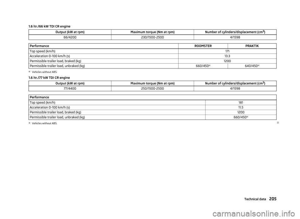
1.6 ltr./66 kW TDI CR engineOutput (kW at rpm)Maximum torque (Nm at rpm)Number of cylinders/displacement (cm3
)66/4200230/1500-25004/1598PerformanceROOMSTERPRAKTIKTop speed (km/h)171Acceleration 0-100 km/h (s)13.3Permissible trailer load, braked (kg)1200Permissible trailer load, unbraked (kg)660/450 a)640/450a)a)
Vehicles without ABS.
1.6 ltr./77 kW TDI CR engine
Output (kW at rpm)Maximum torque (Nm at rpm)Number of cylinders/displacement (cm 3
)77/4400250/1500-25004/1598PerformanceTop speed (km/h)181Acceleration 0-100 km/h (s)11.5Permissible trailer load, braked (kg)1200Permissible trailer load, unbraked (kg)660/450 a)a)
Vehicles without ABS.
205Technical data
Page 209 of 219
Index
A
Abroad Driving abroad
109
Unleaded petrol109
ABS111
Warning light24
Accessories146
Adjusting Exterior mirrors
51
Seat53
Steering wheel95
Adjusting the seats124
Aerial150
See windows152
Airbag132
Deactivating137
Deactivating the front passenger airbag137
Deployment132
Front airbag134
Head airbag136
Modifications and damage to the airbag system 148
Side airbag
135
Airbag system132
Air conditioning Operation
81
Air conditioning system Air outlets
77
Climatronic83
Manual air conditioning system80
Air outlets77
Alarm35
Anti-theft alarm system35
Operation36
Trailer122
Antilock Braking System111
Armrest71
Ashtray66
ASR111
warning light23
Assist systems ABS
24, 111
ASR23, 111
Cruise Control System113
EDS and XDL111
ESC23, 110
Parking aid112
START-STOP115
Auto Check Control19
Automatic gearbox Selector lever-emergency unlocking
103
Starting-off and driving102
Tiptronic102
Automatic load deactivation171
Automatic transmission100
Kickdown102
Malfunction103
Selector lever lock101
Using the selector lever101
AUX94
Avoiding damage to the vehicle Driving through water
108
Avoiding damage to your vehicle108
B
Ball head Check fitting
119
Fitting118
Ready position118
Removing119
Belts127
Belt tensioners131
Bicycle carrier63
Bonnet Closing
161
Opening161
Boot Cover60
Emergency unlocking38
Fastening elements58
Fixing nets59
Folding hooks59
see Boot lid37
Unlocking the boot lid38
Boot lid37
Automatic locking37
Brake assist110
Brake booster99
Brake fluid167
Changing168
Checking167
Display messages20
Brakes Brake booster
99
Brake fluid167
Handbrake99
Indicator light20
Running in104
Braking Information on braking
98
Breakdown kit185
Bulbs In the tail light
198
Replacing194
Button in the driver's door Electrical power windows
38
C
Car care
144
Car computer see Multifunction display
13
Car park ticket holder68
Carrier65
Cavity protection153
Central locking button33
206Index