lock SKODA SUPERB 2003 1.G / (B5/3U) Owner's Guide
[x] Cancel search | Manufacturer: SKODA, Model Year: 2003, Model line: SUPERB, Model: SKODA SUPERB 2003 1.G / (B5/3U)Pages: 259
Page 68 of 259

Lights and Visibility67
Using the systemSafetyDriving TipsGeneral MaintenanceBreakdown assistanceTechnical Data
Automatic dimming interi or rear-view mirror*
The mirror is dimmed automatically depending on the light striking the
mirror from the rear provided the ignition is switched on. The mirror has no
lever on the bottom edge of the mirror. When the interior lights are
switched on or the reverse gear is engaged, the mirror always moves back
into the basic position (not dimmed).
Note
Automatic mirror dimming operates only properly if the sun screen* for the
rear window is not in use or the light striking the rear of the interior rear-
view mirror is not affected by other objects.
Exterior mirror with entry lighting*
The lighting is positioned on the bottom edge of the exte-
rior mirror.
The light beam is aimed at the entry area of the front doors after the car is
unlocked.
The light comes on after the doors have been locked or on opening the
front door. The lighting goes out about 30 seconds after the doors are
closed or if the ignition is switched on.
If the doors remain open, the lighting goes out automatically after about
10 minutes provided the ignition is not switched on.
Electrically adjustable rear mirror
The heating of the external mirror functions only when ignition is
switched on.
Heating of the external mirror
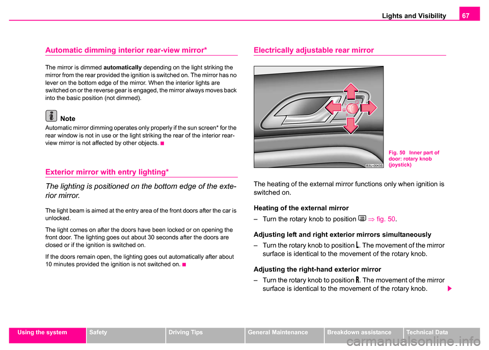
– Turn the rotary knob to position
⇒ fig. 50 .
Adjusting left and right ext erior mirrors simultaneously
– Turn the rotary knob to position
. The movement of the mirror
surface is identical to the movement of the rotary knob.
Adjusting the right-hand exterior mirror
– Turn the rotary knob to position
. The movement of the mirror
surface is identical to the movement of the rotary knob.
Fig. 50 Inner part of
door: rotary knob
(joystick)
Page 71 of 259

Seats and Stowage
70
– Release the lever and push the seat further until the lock is heard to engage.
Adjusting height of seat
– Lift the seat if required by pulling or pumping lever ⇒page 69, fig. 51 upwards.
– Lower the seat if required by pushing or pumping lever downwards.
Adjusting angle of backrest
– Move forward away from the backrest (do not lean against it).
– Turn the handwheel in order to adjust the angle of the backrest accordingly.
Adjusting lumbar support*
– Turn the handwheel until you have set the most comfort- able curvature of the seat upholstery in the area of your spine.
Adjusting front seats electrically*
Adjusting seats
Adjusting seat
– Adopt the correct seated position ⇒page 69.
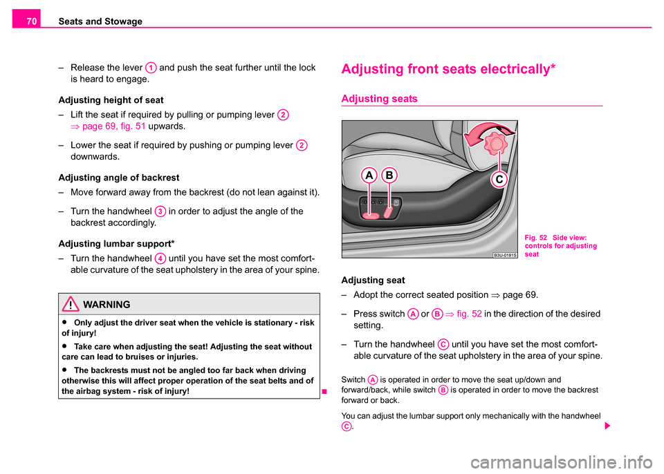
– Press switch or ⇒fig. 52 in the direction of the desired
setting.
– Turn the handwheel until you have set the most comfort- able curvature of the seat upholstery in the area of your spine.
Switch is operated in order to move the seat up/down and
forward/back, while switch is operated in order to move the backrest
forward or back.
You can adjust the lumbar support only mechanically with the handwheel
.
WARNING
•Only adjust the driver seat when the vehicle is stationary - risk
of injury!
•Take care when adjusting the seat! Adjusting the seat without
care can lead to bruises or injuries.
•The backrests must not be angled too far back when driving
otherwise this will affect proper operation of the seat belts and of
the airbag system - risk of injury!
A1
A2
A2
A3
A4
Fig. 52 Side view:
controls for adjusting
seat
AAAB
AC
AAAB
AC
Page 74 of 259

Seats and Stowage73
Using the systemSafetyDriving TipsGeneral MaintenanceBreakdown assistanceTechnical Data
If you wish, you can obtain an additional remote control from a Škoda
Dealer and then assign it to the rear memory button.
Note
•If the remote control had previously been assigned to another memory
button, this setting is then erased by the new assignment.
•If you assign the remote control to a memory button which has already
been assigned to a remote control, the old assignment is also replaced by
a new assignment in this case.
•The assignment of the remote control to a memory button is retained,
however, after reassigning the seats and exterior mirrors.
Retrieving seat and exterior mirror settings for driving
forward
You can retrieve the stored settings either with the
memory buttons or with the remote control*.
Retrieving settings with memory buttons
– For safety reasons, you can only retrieve the seat and mirror
settings if the ignition is switched off. You have a choice of two
different ways of retrieving the settings:
– One-touch automatic memory: with the driver door open,
operate the desired memory button ⇒page 71, fig. 53
with one-touch. The seat and the exterior mirrors now move
automatically into the stored position.
– Memory keying : with the driver door open or closed, press
and hold the desired memory button until the seat and the
exterior mirrors have moved into the stored position. Retrieving settings with remote control
– If the driver door is closed and the ignition is switched off,
briefly press the unlock button of the remote control
⇒page 46 and then open the door.
– The seat and exterior mirrors now move automatically into the stored positions.
Retrieving setting of exterior mirror for reversing*
– Engage reverse gear and then move the control for the exte- rior mirror setting into position
⇒ page 67.
Emergency Off
You can interrupt any memory retrieval operation in an emergency by
pressing the switch ⇒page 71, fig. 53 , by one-touch of a memory
button or by pressing the seat setting switch.
AD
AD
AE
Page 75 of 259

Seats and Stowage
74
Head restraintsAdjusting the height of a head restraint
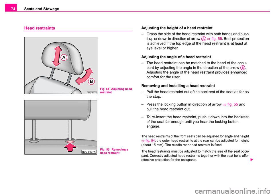
– Grasp the side of the head restraint with both hands and push
it up or down in direction of arrow ⇒fig. 55 . Best protection
is achieved if the top edge of the head restraint is at least at
eye level or higher.
Adjusting the angle of a head restraint
– The head restraint can be matched to the head of the occu- pant by adjusting the angle in the direction of the arrow .
Adjusting the angle of the head restraint provides enhanced
comfort for the user.
Removing and installing a head restraint
– Pull the head restraint out of the backrest of the seat as far as the stop.
– Press the locking button in direction of arrow ⇒fig. 55 and
pull the head restraint out.
– To re-insert the head restraint, push it down into the backrest of the seat far enough until you hear the locking button
engage.
The head restraints of the front seats can be adjusted for angle and height
⇒fig. 54, the outer head restraints at the rear can be adjusted for height
(about 15 mm). The middle rear head restraint is fixed.
The head restraints must be adjusted to match the size of the seat occu-
pant. Correctly adjusted head restraints together with the seat belts offer
effective protection for the occupants.
Fig. 54 Adjusting head
restraint
Fig. 55 Removing a
head restraint
AA
AB
Page 76 of 259

Seats and Stowage75
Using the systemSafetyDriving TipsGeneral MaintenanceBreakdown assistanceTechnical Data
Front passenger seat with a folding
central back rest*
Folding out and setting
You can fold out the central back rest of the front passenger seat
during a long journey for improved comfort. It then serves as a
comfortable footrest for the passengers in the rear. You can
adjust the position of the footrest by adjusting the passenger seat
using the switches in the armrest of the rear seats ⇒fig. 57 .
Folding out the central back rest
– Pull the handle in direction of arrow ⇒fig. 56 and pull the
central part of the back rest downwards.
Folding up the central back rest
– Fold the central back rest up until it is heard to lock.
Adjusting the passenger seat
– Tilt the back rest forwards or backwards using switch .
– Move the front part of the seat upwards or downwards using switch .
WARNING
The head restraints must be corr ectly adjusted in order to offer
effective protection to the occupants in the event of an accident.
Fig. 56 Front
passenger seat: folding
central back rest
Fig. 57 Armrest of rear
seats: Operating the
passenger seat
AA
AB
Page 81 of 259

Seats and Stowage
80
Folding double hooks
Folding double hooks for attaching small items of luggage, such as bags
etc., are provided on both sides of the luggage compartment ⇒fig. 63.
An item of luggage weighing up to 5 kg can be attached to each side of
the double hook.
Side compartment
– You can open the compartment by turning the locks in the direction of arrow ⇒fig. 64 .
The CD changer* and the first-aid box* ⇒page 227 is housed in this
compartment.
The luggage compartment cover
You can use the luggage compartment cover behind the head restraints
of the rear seats for storing light and soft items.
Fig. 63 Folding double
hooksFig. 64 Luggage
compartment: Side
compartment
Page 82 of 259

Seats and Stowage81
Using the systemSafetyDriving TipsGeneral MaintenanceBreakdown assistanceTechnical Data
Caution
Please ensure that the heating elements of the rear window heater are not
damaged as a result of objects placed in this area.
Through-loading bag*
The through-loading bag enables you to conveniently
transport long objects (such as skis) without damaging the
interior of the car.
Loading
– Fold down the armrest of the rear seats to the front.
– Press the unlock button for the cover of the through-loading
bag in the interior of the car and swivel it down.
– Pull the bag out and unfold it.
– Open the boot lid/luggage compartment door.
– Press the unlock button for the cover of the through-loading bag ⇒fig. 65 and swivel it down.
– Push the objects into the through-loading bag from the boot ⇒ .
Securing
– Insert the belt ⇒fig. 66 into the middle seat belt buckle .
WARNING
No objects should be placed on the luggage compartment cover,
the vehicle occupants could be endangered if there is sudden
braking or the vehicle collides with something.
Fig. 65 Luggage
compartment: cover for
through-loading bag
Fig. 66 Attaching
through-loading bag to
middle seat belt buckle
of rear seats
AAAB
Page 83 of 259

Seats and Stowage
82
– Pull the seat belt tight in direction of arrow ⇒page 81,
fig. 66 .
Stowing
– Close the cover for the through-loading bag in the boot.
– Carefully fold the through-loading bag together (approx. 11 cm packet).
– Close the cover in the interior of the car.
– Move the armrest back into its original position.
Note
Never fold the though-loading bag together if it is moist.
The cool box in the armrest of rear seats*
Using the system
The contents of the cool box is cooled to a temperature of about
20 °C below the ambient temperature, but to a maximum of
approx.+ 5 °C.
Opening and Closing
– Pull the handle ⇒fig. 67 and pull the lid downwards.
– Open up the lid of the cool box upwards until it is heard to lock.
Switching on and off
– The cooling action of the cool box is switched on and off using switch ⇒fig. 67 . It is signalised by the lighting up of the
indicator light on the switch.
WARNING
After placing items into the through-loading bag, you must secure
the bag with the belt .
AC
AAFig. 67 Cool box
AA
Page 85 of 259

Seats and Stowage
84
Removing and installing the cool box
Removing
– Switch the cooling mode of the cool box off ⇒page 82. – Remove the locking mechanism
⇒fig. 69 .
– Open the lid of the cool box.
– Press open the upper side of the cool box from the inside in the direction of arrow and put away the cool box in the
luggage compartment (see arrow ).
– Unplug the plug connector (the plug connector is located in the luggage compartment in the lower part of the fixing frame
for the cool box).
Installing
– Place the cool box on the luggage compartment partition and plug in the plug.
– Remove the locking mechanism ⇒fig. 69 .
– Fold the lid of the cool box onto the fixing frame ⇒fig. 70 .
– Lift the cool box with the palm of the hand on the inside of the upper wall of the cool box.
– Insert the cool box with the lower edge into the lower holding bracket on the luggage compartment partition.
– Pull the cool box forwards to the upper edge until the stop (see arrow ), press with the palm of the hand onto the upper wall
(see arrow ), pull the box again forwards and press down-
wards (see arrow ).
– Push the locking mechanism ⇒fig. 69 up to the stop into
the fixing frame.
– Close the lid of the cool box.
Fig. 69 Removing the
cool box
Fig. 70 Installing the
cool box
AA
A1
A2
AA
A1
A2
A3
AA
Page 86 of 259

Seats and Stowage85
Using the systemSafetyDriving TipsGeneral MaintenanceBreakdown assistanceTechnical Data
CargoFlex folding box*
Lowering and securing folding box
You can transport the folding box in two different positions - in the
transport position against the partition ⇒fig. 71 of the luggage
compartment, or in the ready position lowered onto the floor of
the luggage compartment ⇒ fig. 72.
Lowering folding box in to the ready position
– Pull the snap handle in direction of arrow 1 ⇒ fig. 71 . The
folding box is lowered to just above the floor of the luggage
compartment.
– Press the folding box at the arrow positions 2 ⇒ fig. 72 onto
the floor of the luggage compartment until it locks in place. If
correctly locked, the snap handle moves back into its initial
position (the top red surface of the handle is not visible).
Securing folding box in the transport position against
partition of luggage compartment
– Lower the folding box into the ready position ⇒page 87.
– Pull the snap handle in direction of arrow 1 ⇒ page 85, fig. 71 .
The folding box is raised up from the luggage compartment
floor.
– Raise and press the folding box against the partition of the luggage compartment, it is secured audibly in this way in the
transport position. If correctly locked, the snap handle moves
back into its initial position (the top red surface of the handle
is not visible).
Opening folding box ⇒page 86.
Fig. 71 Folding box:
Transport position
Fig. 72 Folding box:
ready position