warning light SKODA SUPERB 2004 1.G / (B5/3U) Owner's Guide
[x] Cancel search | Manufacturer: SKODA, Model Year: 2004, Model line: SUPERB, Model: SKODA SUPERB 2004 1.G / (B5/3U)Pages: 270
Page 47 of 270
Unlocking and locking
46
Open boot lid
– Press on the handle ⇒ page 45, fig. 26 and at the same time
raise the boot lid.
Close the boot lid
– Pull the boot lid down and close it with a slight swing ⇒.
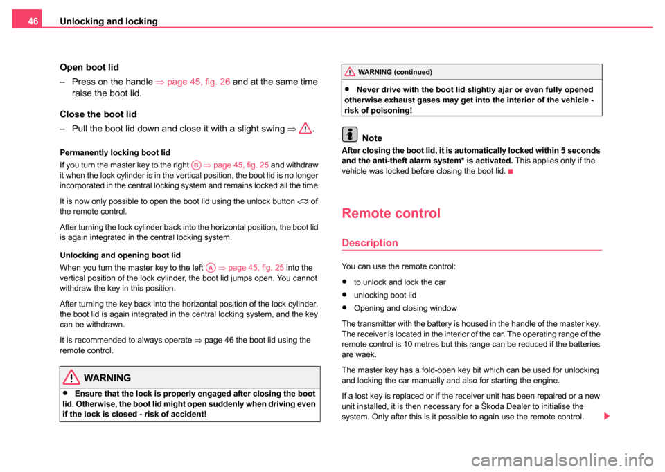
Permanently locking boot lid
If you turn the master key to the right ⇒ page 45, fig. 25 and withdraw
it when the lock cylinder is in the vertical position, the boot lid is no longer
incorporated in the central locking system and remains locked all the time.
It is now only possible to open the boot lid using the unlock button
of
the remote control.
After turning the lock cylinder back into the horizontal position, the boot lid
is again integrated in the central locking system.
Unlocking and opening boot lid
When you turn the master key to the left ⇒page 45, fig. 25 into the
vertical position of the lock cylinder, the boot lid jumps open. You cannot
withdraw the key in this position.
After turning the key back into the horizontal position of the lock cylinder,
the boot lid is again integrated in the central locking system, and the key
can be withdrawn.
It is recommended to always operate ⇒page 46 the boot lid using the
remote control.
WARNING
•Ensure that the lock is properly engaged after closing the boot
lid. Otherwise, the boot lid might open suddenly when driving even
if the lock is closed - risk of accident!
•Never drive with the boot lid sli ghtly ajar or even fully opened
otherwise exhaust gases may get into the interior of the vehicle -
risk of poisoning!
Note
After closing the boot lid, it is au tomatically locked within 5 seconds
and the anti-theft alarm system* is activated. This applies only if the
vehicle was locked before closing the boot lid.
Remote control
Description
You can use the remote control:
•to unlock and lock the car
•unlocking boot lid
•Opening and closing window
The transmitter with the battery is housed in the handle of the master key.
The receiver is located in the interior of the car. The operating range of the
remote control is 10 metres but this range can be reduced if the batteries
are waek.
The master key has a fold-open key bit which can be used for unlocking
and locking the car manually and also for starting the engine.
If a lost key is replaced or if the receiver unit has been repaired or a new
unit installed, it is then necessary for a Škoda Dealer to initialise the
system. Only after this is it possible to again use the remote control.
AB
AA
WARNING (continued)
Page 57 of 270
Lights and Visibility
56
Lights and Visibility
Lights
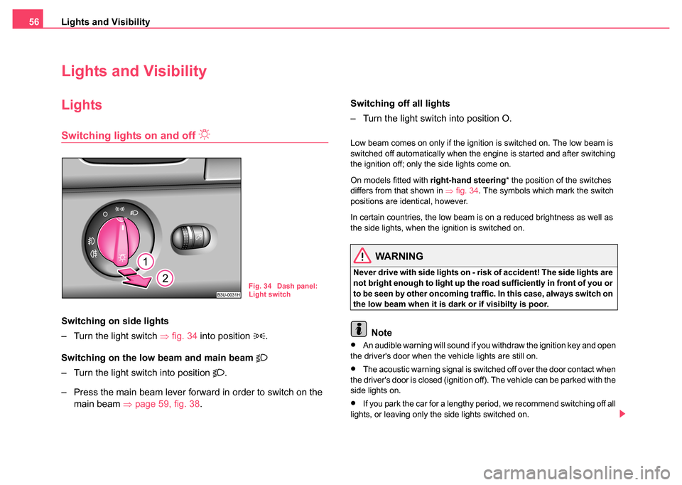
Switching lights on and off
Switching on side lights
– Turn the light switch ⇒fig. 34 into position
.
Switching on the low beam and main beam
– Turn the light switch into position .
– Press the main beam lever forward in order to switch on the main beam ⇒page 59, fig. 38 . Switching off all lights
– Turn the light switch into position O.
Low beam comes on only if the ignition is switched on. The low beam is
switched off automatically when the engine is started and after switching
the ignition off; only the side lights come on.
On models fitted with
right-hand steering* the position of the switches
differs from that shown in ⇒fig. 34 . The symbols which mark the switch
positions are identical, however.
In certain countries, the low beam is on a reduced brightness as well as
the side lights, when the ignition is switched on.
WARNING
Never drive with side lights on - ri sk of accident! The side lights are
not bright enough to light up the road sufficiently in front of you or
to be seen by other oncoming traffic. In this case, always switch on
the low beam when it is dark or if visibilty is poor.
Note
•An audible warning will sound if you withdraw the ignition key and open
the driver's door when the vehicle lights are still on.
•The acoustic warning signal is switched off over the door contact when
the driver's door is closed (ignition off). The vehicle can be parked with the
side lights on.
•If you park the car for a lengthy period, we recommend switching off all
lights, or leaving only the side lights switched on.
Fig. 34 Dash panel:
Light switch
Page 58 of 270
Lights and Visibility57
Using the systemSafetyDriving TipsGeneral MaintenanceBreakdown assistanceTechnical Data
•The switching on of the described lights should only be undertaken in
accordance with the legal requirements.
Fog lights
Switching on the fog lights
– First of all turn the light switch ⇒page 56, fig. 34 into position
or .
– Pull the light switch out to the first detent .
The rear fog light warning light ⇒ page 31 lights up in the instrument
cluster when the fog light is switched off.
The rear fog light
Switching on the rear fog light
– First of all turn the light switch ⇒page 56, fig. 34 into position
or .
– Pull the light switch out to the second detent .
The rear fog light warning light ⇒ page 31 lights up in the instrument
cluster when the fog light is switched off.
Only the rear fog light of the trailer lights up automatically when you are
towing a trailer using a factory-fitted towing device which is fitted with
the rear fog light .
Caution
The rear fog light should only be switched on if visibility is particularly poor
(conform with any varying legal provisions) to avoid dazzling vehicles
behind your vehicle.
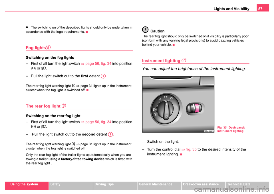
Instrument lighting
You can adjust the brightness of the instrument lighting.
– Switch on the light.
– Turn the control dial ⇒fig. 35 to the desired intensity of the
instrument lighting.
A1
A2
Fig. 35 Dash panel:
Instrument lighting
Page 59 of 270
Lights and Visibility
58
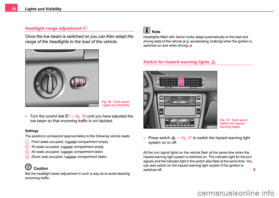
Headlight range adjustment
Once the low beam is switched on you can then adapt the
range of the headlights to the load of the vehicle.
– Turn the control dial ⇒ fig. 36 until you have adjusted the
low beam so that oncoming traffic is not dazzled.
Settings
The positions correspond approximately to the following vehicle loads:
Front seats occupied, luggage compartment empty.
All seats occupied, luggage compartment empty.
All seats occupied, luggage compartment laden.
Driver seat occupied, luggage compartment laden.
Caution
Set the headlight beam adjustment in such a way as to avoid dazzling
oncoming traffic.
Note
Headlights fitted with Xenon bulbs adapt automatically to the load and
driving state of the vehicle (e.g. accelerating, braking) when the ignition is
switched on and when driving.
Switch for hazard warning lights
– Press switch ⇒ fig. 37 to switch the hazard warning light
system on or off.
All the turn signal lights on the vehicle flash at the same time when the
hazard warning light system is switched on. The indicator light for the turn
signals and the indicator light in the switch also flash at the same time. You
can also switch on the hazard warning light system if the ignition is
switched off.
Fig. 36 Dash panel:
Lights and Visibility
A-
A1
A2
A3
Fig. 37 Dash panel:
Switch for hazard
warning lights
Page 60 of 270
Lights and Visibility59
Using the systemSafetyDriving TipsGeneral MaintenanceBreakdown assistanceTechnical Data
Please comply with any legal requirements when using the hazard
warning light system.
Note
Switch on the hazard warning light system if, for example:
•you encounter traffic congestion,
•your car breaks down or an emergency situation occurs,
Turn signal and main beam lever
The parking lights and headlight flasher are also switched
on and off using the turn signal and main beam lever.
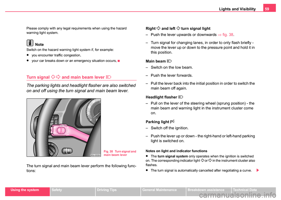
The turn signal and main beam lever perform the following func-
tions:
Right
and left turn signal light
– Push the lever upwards or downwards ⇒fig. 38 .
– Turn signal for changing lanes, in order to only flash briefly - move the lever up or down to the pressure point and hold it in
this position.
Main beam
– Switch on the low beam.
– Push the lever forwards.
– Pull the lever back into the initial position in order to switch the main beam off again.
Headlight flasher
– Pull on the lever of the steering wheel (sprung position) - the main beam and warning light in the instrument cluster come
on.
Parking light
– Switch off the ignition.
– Push the lever up or down - the right-hand or left-hand parking light is switched on.
Notes on light and indicator functions
•The turn signal system only operates when the ignition is switched
on. The corresponding indicator light or in the instrument cluster also
flashes.
•The turn signal is automatically cancelled after negotiating a curve.
Fig. 38 Turn signal and
main beam lever
Page 61 of 270
Lights and Visibility
60
•The side light and rear light on the appropriate side of the vehicle are
switched on when the parking light is selected. The parking light function
only operates if the ignition is switched off.
•An acoustic warning signal will sound when the driver's door is opened
if the lever is not in the middle position after removing the ignition key. The
acoustic warning signal will stop just as soon as the driver's door is closed.
Caution
Use main beam or the headlight flasher only if this does not risk dazzling
other road users.
Note
Use only in accordance with the legal requirements the described lighting
and signal systems.
Coming Home Function
This function makes it possible to switch on low or main beam for
a short time after leaving the car, e.g. to illuminate the path to
your front door, etc.
Selecting function
– Switch off the light.
– Switch off the ignition.
– Flash one time with the headlights.
– Open the door, the low beam lights up.
If you shift the lever into the main beam position, the main beam lights up. If the door remains open, the light remains on for about 3 minutes.
If the door is closed, the light remains on for about 30 seconds.
Interior lighting
Front interior lighting and storage compartment on
front passenger side
Door contact setting
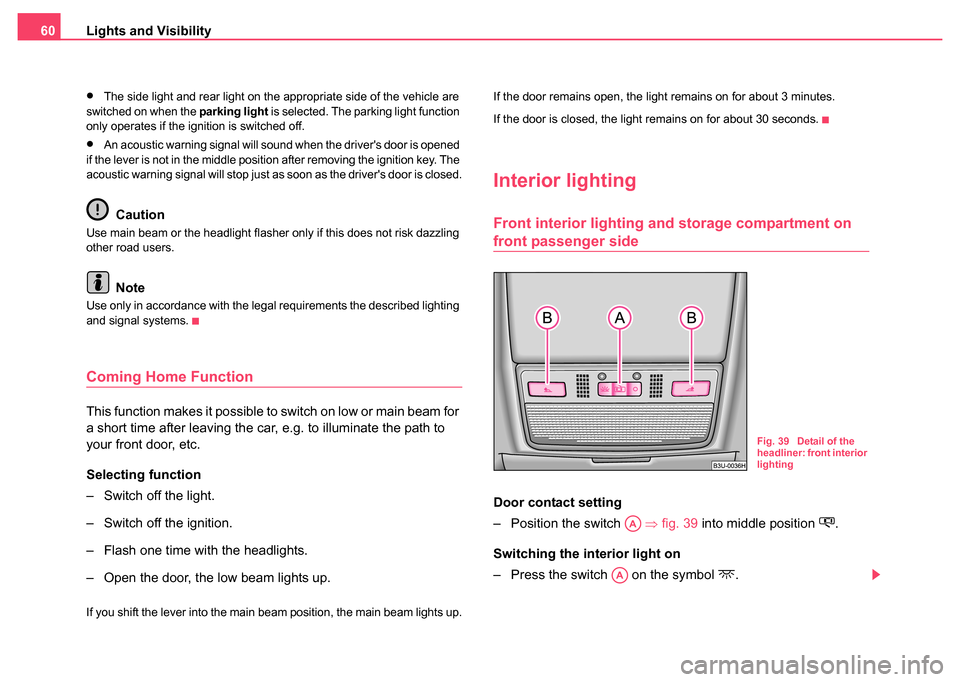
– Position the switch
⇒fig. 39 into middle position
.
Switching the interior light on
– Press the switch on the symbol
.
Fig. 39 Detail of the
headliner: front interior
lighting
AA
AA
Page 66 of 270
Lights and Visibility65
Using the systemSafetyDriving TipsGeneral MaintenanceBreakdown assistanceTechnical Data
– If you have switched the ignition off and on again, you must
then once again activate the sensor by moving the lever into
home position , and then back into position .
The windscreen wipers and the windscreen washer system only operate
if the ignition is switched on.
The windscreen washer nozzles are heated* when the ignition is switched
on.
The rain sensor* automatically regulates the break between the individual
wiper strokes depending on the intensity of the rain.
Top up with wash liquid ⇒page 223.
WARNING
•Properly maintained windscreen wiper blades are essential for
clear visibility and safe driving ⇒ page 66, “Replacing windscreen
wiper blades”.
•Do not use the windscreen washer system at low temperatures,
without heating the windscreen beforehand. Otherwise the window
cleaner could freeze on the windscreen and restrict the view to the
front.
Caution
In frosty weather, please first of all check whether the windscreen wiper
blades are not frozen to the windscreen before switching them on.
Switching on windscreen wipers when the blades are frozen to the wind-
screen may result in damage both to the blades and the motor of the wind-
screen wipers!
Headlight cleaning system*
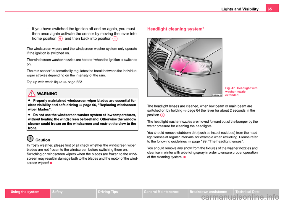
The headlight lenses are cleaned, when low beam or main beam are
switched on by holding ⇒page 64 the lever for about 2 seconds in the
position .
The headlight washer nozzles are moved forward out of the bumper by the
water pressure for cleaning the headlights.
You should remove stubborn dirt (such as insect residues) from the head-
light lenses at regular intervals, for example when refuelling. Please refer
to the following guidelines ⇒page 199, “The headlight lenses”.
You should remove any snow from the fixtures of the washer nozzles and
clear ice in winter with a de-icing spray in order to ensure proper operation
of the cleaning system.
A0A1
Fig. 47 Headlight with
washer nozzle
extended
A5
Page 67 of 270
Lights and Visibility
66
Replacing windscreen wiper blades
Taking off the wiper blade
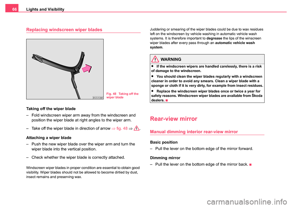
– Fold windscreen wiper arm away from the windscreen and
position the wiper blade at right angles to the wiper arm.
– Take off the wiper blade in direction of arrow ⇒fig. 48 ⇒ .
Attaching a wiper blade
– Push the new wiper blade over the wiper arm and turn the wiper blade into the vertical position.
– Check whether the wiper blade is correctly attached.
Windscreen wiper blades in proper condition are essential to obtain good
visibility. Wiper blades should not be allowed to become dirtied by dust,
insect remains and preserving wax. Juddering or smearing of the wiper blades could be due to wax residues
left on the windscreen by vehicle washing in automatic vehicle wash
systems. It is therefore important to
degrease the lips of the winscreen
wiper blades after every pass through an automatic vehicle wash
system .
WARNING
•If the windscreen wipers are handled carelessly, there is a risk
of damage to the windscreen.
•You should clean the wiper blades regularly with a windscreen
cleaner in order to avoid any smears. Clean a wiper blade with a
sponge or cloth if it is very dirty, for example from insect residues.
•Replace the windscreen wiper blades once or twice a year for
safety reasons. Windscreen wiper blades are available from Škoda
dealers.
Rear-view mirror
Manual dimming interior rear-view mirror
Basic position
– Pull the lever on the bottom edge of the mirror forward.
Dimming mirror
– Pull the lever on the bottom edge of the mirror back.
Fig. 48 Taking off the
wiper blade
Page 69 of 270
Lights and Visibility
68
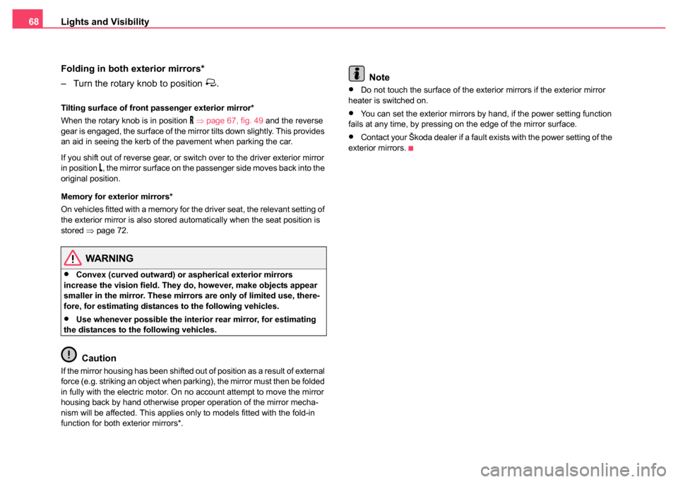
Folding in both exterior mirrors*
– Turn the rotary knob to position
.
Tilting surface of front passenger exterior mirror*
When the rotary knob is in position
⇒ page 67, fig. 49 and the reverse
gear is engaged, the surface of the mirror tilts down slightly. This provides
an aid in seeing the kerb of the pavement when parking the car.
If you shift out of reverse gear, or switch over to the driver exterior mirror
in position
, the mirror surface on the passenger side moves back into the
original position.
Memory for exterior mirrors*
On vehicles fitted with a memory for the driver seat, the relevant setting of
the exterior mirror is also stored automatically when the seat position is
stored ⇒page 72.
WARNING
•Convex (curved outward) or aspherical exterior mirrors
increase the vision field. They do, however, make objects appear
smaller in the mirror. These mirrors are only of limited use, there-
fore, for estimating distances to the following vehicles.
•Use whenever possible the interior rear mirror, for estimating
the distances to the following vehicles.
Caution
If the mirror housing has been shifted out of position as a result of external
force (e.g. striking an object when parking), the mirror must then be folded
in fully with the electric motor. On no account attempt to move the mirror
housing back by hand otherwise proper operation of the mirror mecha-
nism will be affected. This applies only to models fitted with the fold-in
function for both exterior mirrors*.
Note
•Do not touch the surface of the exterior mirrors if the exterior mirror
heater is switched on.
•You can set the exterior mirrors by hand, if the power setting function
fails at any time, by pressing on the edge of the mirror surface.
•Contact your Škoda dealer if a fault exists with the power setting of the
exterior mirrors.
Page 71 of 270
Seats and Stowage
70
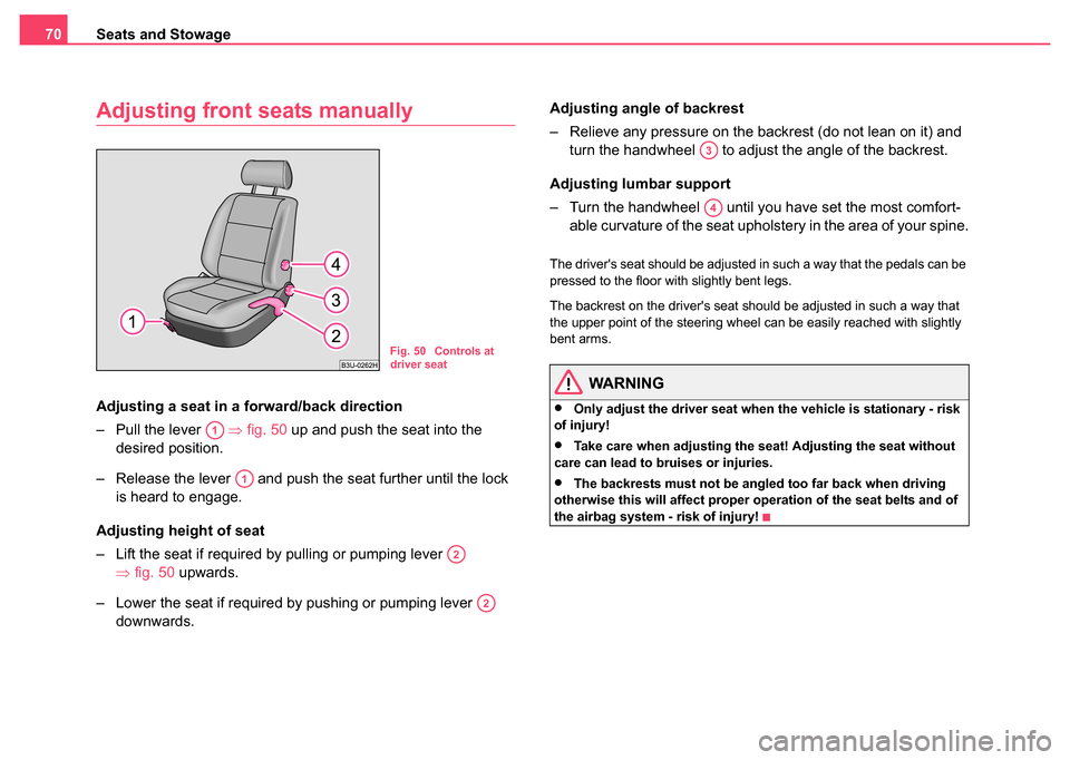
Adjusting front seats manually
Adjusting a seat in a fo rward/back direction
– Pull the lever ⇒fig. 50 up and push the seat into the
desired position.
– Release the lever and push the seat further until the lock is heard to engage.
Adjusting height of seat
– Lift the seat if required by pulling or pumping lever ⇒fig. 50 upwards.
– Lower the seat if required by pushing or pumping lever downwards. Adjusting angle of backrest
– Relieve any pressure on the backrest (do not lean on it) and
turn the handwheel to adjust the angle of the backrest.
Adjusting lumbar support
– Turn the handwheel until you have set the most comfort- able curvature of the seat upholstery in the area of your spine.
The driver's seat should be adjusted in such a way that the pedals can be
pressed to the floor with slightly bent legs.
The backrest on the driver's seat should be adjusted in such a way that
the upper point of the steering wheel can be easily reached with slightly
bent arms.
WARNING
•Only adjust the driver seat when the vehicle is stationary - risk
of injury!
•Take care when adjusting the seat! Adjusting the seat without
care can lead to bruises or injuries.
•The backrests must not be angled too far back when driving
otherwise this will affect proper operation of the seat belts and of
the airbag system - risk of injury!
Fig. 50 Controls at
driver seat
A1
A1
A2
A2
A3
A4