technical data SKODA SUPERB 2005 1.G / (B5/3U) Owner's Manual
[x] Cancel search | Manufacturer: SKODA, Model Year: 2005, Model line: SUPERB, Model: SKODA SUPERB 2005 1.G / (B5/3U)Pages: 281
Page 4 of 281
Introduction3
Technical Data
includes the most important identification data of your vehicle.
s3ec.book Seite 3 Montag, 2. Mai 2005 3:42 15
Page 7 of 281
Contents
6
Driving Tips . . . . . . . . . . . . . . . . . . . . . .
Intelligent Technology . . . . . . . . . . . . . . . . . .
Electronic stability programme (ESP)* . . . . . .
Brakes . . . . . . . . . . . . . . . . . . . . . . . . . . . . . .
Brake booster . . . . . . . . . . . . . . . . . . . . . . . .
Antilock brake system (ABS) . . . . . . . . . . . . .
Brake Assist* . . . . . . . . . . . . . . . . . . . . . . . . .
Power steering . . . . . . . . . . . . . . . . . . . . . . . .
Driving and the Environment. . . . . . . . . . . .
The first 1 500 kilometres and then afterwards
Catalytic converter . . . . . . . . . . . . . . . . . . . . .
Driving in an economical and environmentally
conscious manner . . . . . . . . . . . . . . . . . . . . .
Environmental compatibility . . . . . . . . . . . . . .
Motoring abroad . . . . . . . . . . . . . . . . . . . . . . .
Avoiding damage to your vehicle . . . . . . . . . .
Towing a trailer . . . . . . . . . . . . . . . . . . . . . . . .
Towing a trailer . . . . . . . . . . . . . . . . . . . . . . . .
Detachable towing device* . . . . . . . . . . . . . .
General Maintenance . . . . . . . . . .
Taking care of your vehicle and cleaning the
vehicle. . . . . . . . . . . . . . . . . . . . . . . . . . . . . . . .
General . . . . . . . . . . . . . . . . . . . . . . . . . . . . .
Care of the exterior of vehicle . . . . . . . . . . . .
Care of the interior of vehicle . . . . . . . . . . . . .
Fuel. . . . . . . . . . . . . . . . . . . . . . . . . . . . . . . . . .
Petrol . . . . . . . . . . . . . . . . . . . . . . . . . . . . . . .
Diesel . . . . . . . . . . . . . . . . . . . . . . . . . . . . . . .
Refuelling . . . . . . . . . . . . . . . . . . . . . . . . . . . .
Inspecting and Replenishing. . . . . . . . . . . .
Engine compartment . . . . . . . . . . . . . . . . . . .
Overview of the engine compartment . . . . . .
Engine oil . . . . . . . . . . . . . . . . . . . . . . . . . . . . Cooling system . . . . . . . . . . . . . . . . . . . . . . .
Brake fluid . . . . . . . . . . . . . . . . . . . . . . . . . . .
The battery . . . . . . . . . . . . . . . . . . . . . . . . . .
Windscreen Wiper and Washer System . . . .
Wheels and Tyres . . . . . . . . . . . . . . . . . . . . .
Wheels . . . . . . . . . . . . . . . . . . . . . . . . . . . . .
Accessories, changes and replacement of
parts . . . . . . . . . . . . . . . . . . . . . . . . . . . . . . . . .
Accessories and replacement parts . . . . . . .
Technical changes . . . . . . . . . . . . . . . . . . . . .
Breakdown assistance . . . . . . . .
Breakdown assistance . . . . . . . . . . . . . . . . .
First-aid box* . . . . . . . . . . . . . . . . . . . . . . . . .
Warning triangle . . . . . . . . . . . . . . . . . . . . . .
Fire extinguisher* . . . . . . . . . . . . . . . . . . . . . .
Vehicle tool kit . . . . . . . . . . . . . . . . . . . . . . . .
Spare wheel . . . . . . . . . . . . . . . . . . . . . . . . . .
Changing a wheel . . . . . . . . . . . . . . . . . . . . .
Jump-starting . . . . . . . . . . . . . . . . . . . . . . . . .
Tow-starting and towing vehicle . . . . . . . . . . .
Fuses and light bulbs . . . . . . . . . . . . . . . . . .
Electric fuses . . . . . . . . . . . . . . . . . . . . . . . . .
Bulbs . . . . . . . . . . . . . . . . . . . . . . . . . . . . . . .
Technical Data. . . . . . . . . . . . . . . . . . .
General . . . . . . . . . . . . . . . . . . . . . . . . . . . . . .
Identification data . . . . . . . . . . . . . . . . . . . . .
Index. . . . . . . . . . . . . . . . . . . . . . . . . . . . . . .
185
185
185
188
189
189
190
191
192
192
193
194
198
199
199
200
200
202
205
205
205
205
211
214
214
214
216
218
218
220
221 224
227
228
233
235
235
243
243
243
245
245
245
245
246
246
247
248
255
257
260
260
262
269
269
269
271
s3ec.book Seite 6 Montag, 2. Mai 2005 3:42 15
Page 10 of 281
9
Using the systemSafetyDriving TipsGeneral MaintenanceBreakdown assistanceTechnical Data
Using the system
s3ec.book Seite 9 Montag, 2. Mai 2005 3:42 15
Page 12 of 281
Cockpit11
Using the systemSafetyDriving TipsGeneral MaintenanceBreakdown assistanceTechnical Data
Cockpit
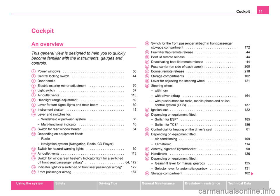
An overview
This general view is designed to help you to quickly
become familiar with the instruments, gauges and
controls.
Power windows . . . . . . . . . . . . . . . . . . . . . . . . . . . . . . . . . .
Central locking switch . . . . . . . . . . . . . . . . . . . . . . . . . . . . .
Door handle
Electric exterior mirror adjustment . . . . . . . . . . . . . . . . . . . .
Light switch . . . . . . . . . . . . . . . . . . . . . . . . . . . . . . . . . . . . .
Air outlet vents . . . . . . . . . . . . . . . . . . . . . . . . . . . . . . . . . . .
Headlight range adjustment . . . . . . . . . . . . . . . . . . . . . . . . .
Lever for turn signal lights and main beam . . . . . . . . . . . . .
Instrument cluster . . . . . . . . . . . . . . . . . . . . . . . . . . . . . . . .
Lever and switches for:
−Windshield wiper/wash system . . . . . . . . . . . . . . . . . . . .
− Multi-functional indicator . . . . . . . . . . . . . . . . . . . . . . . . .
Switch for rear window heater . . . . . . . . . . . . . . . . . . . . . . .
Depending on equipment fitted:
− Radio
− Navigation system (Navigation, Radio, CD Player)
Switch for hazard warning lights . . . . . . . . . . . . . . . . . . . . .
Air outlet vents . . . . . . . . . . . . . . . . . . . . . . . . . . . . . . . . . . .
Switch for windscreen heater* / Indicator light for a switched
off front seat passenger airbag* . . . . . . . . . . . . . . . . . . . . . .
Indicator light for a switched off front seat passenger airbag*
Front passenger airbag . . . . . . . . . . . . . . . . . . . . . . . . . . . . Switch for the front passenger airbag* in front passenger
stowage compartment . . . . . . . . . . . . . . . . . . . . . . . . . . . .
Fuel filler flap remote release . . . . . . . . . . . . . . . . . . . . . . .
Boot lid remote release . . . . . . . . . . . . . . . . . . . . . . . . . . . .
Deactivating boot lid remote release . . . . . . . . . . . . . . . . .
Fuse carrier (on side of dash panel) . . . . . . . . . . . . . . . . . .
Bonnet remote release . . . . . . . . . . . . . . . . . . . . . . . . . . . .
Storage compartments . . . . . . . . . . . . . . . . . . . . . . . . . . . .
Lever for adjusting the steering wheel . . . . . . . . . . . . . . . .
Steering wheel:
−
with horn
− with driver airbag . . . . . . . . . . . . . . . . . . . . . . . . . . . . . .
− with pushbuttons for radio, mobile phone and cruise
control system (CCS) . . . . . . . . . . . . . . . . . . . . . . . . . . .
Ignition lock . . . . . . . . . . . . . . . . . . . . . . . . . . . . . . . . . . . . .
Depending on equipment fitted:
− Switch for ESP* . . . . . . . . . . . . . . . . . . . . . . . . . . . . . . .
− Switch for TCS* . . . . . . . . . . . . . . . . . . . . . . . . . . . . . . .
Control dial for heating on the driver's seat . . . . . . . . . . . .
Depending on equipment fitted:
− Air conditioning . . . . . . . . . . . . . . . . . . . . . . . . . . . . . . . .
− Climatronic . . . . . . . . . . . . . . . . . . . . . . . . . . . . . . . . . . .
Ashtray, cigarette lighter/socket . . . . . . . . . . . . . . . . . . . . .
Handbrake . . . . . . . . . . . . . . . . . . . . . . . . . . . . . . . . . . . . .
Depending on equipment fitted:
− Gearshift lever for manual gearbox . . . . . . . . . . . . . . . .
− Selector lever for automatic gearbox . . . . . . . . . . . . . . .
Storage compartment . . . . . . . . . . . . . . . . . . . . . . . . . . . . . A150
A244
A3
A470
A557
A611 3
A759
A860
A913
A10
66
18
A1164
A12
A1360
A1411 3
A1564, 172
A16172
A17164
A18172
A1944
A2044
A2144
A22260
A23218
A24102
A25121
A26
164
137
A27122
A28
185
186
A2981
A30
109
11 4
A3198
A32126
A33
125
131
A34102
s3ec.book Seite 11 Montag, 2. Mai 2005 3:42 15
Page 14 of 281
Instruments and Indicator/Warning Lights13
Using the systemSafetyDriving TipsGeneral MaintenanceBreakdown assistanceTechnical Data
Instruments and Indicator/Warning Lights
General view of the instrument cluster
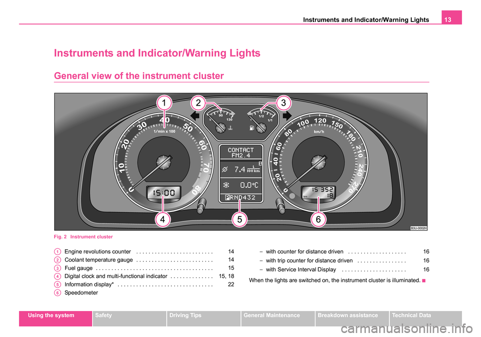
Fig. 2 Instrument cluster
Engine revolutions counter . . . . . . . . . . . . . . . . . . . . . . . . .
Coolant temperature gauge . . . . . . . . . . . . . . . . . . . . . . . . .
Fuel gauge . . . . . . . . . . . . . . . . . . . . . . . . . . . . . . . . . . . . . .
Digital clock and multi-functional indicator . . . . . . . . . . . . . .
Information display* . . . . . . . . . . . . . . . . . . . . . . . . . . . . . . .
Speedometer −
with counter for distance driven . . . . . . . . . . . . . . . . . . .
− with trip counter for distance driven . . . . . . . . . . . . . . . .
− with Service Interval Display . . . . . . . . . . . . . . . . . . . . .
When the lights are switched on, the instrument cluster is illuminated.A114
A214
A315
A415, 18
A522
A6
16
16
16
s3ec.book Seite 13 Montag, 2. Mai 2005 3:42 15
Page 16 of 281
Instruments and Indicator/Warning Lights15
Using the systemSafetyDriving TipsGeneral MaintenanceBreakdown assistanceTechnical Data
Fuel gauge
The fuel gauge ⇒page 13, fig. 2 only operates when the ignition is
switched on.
The fuel tank has a capacity of about 62 litres. The warning symbol
in
the instrument cluster lights up when the pointer reaches the reserve
marking. There are now about 8 litres of fuel remaining in the tank. This
symbol is a reminder for you, that you must refuel.
The following will be displayed in the information display*: PLEASE REFUEL
A peep sounds as an additional warning signal.
Caution
Never run the fuel tank completely empty! An irregular fuel supply can
result in poor ignition or misfiring. Unburnt fuel may get into the exhaust
system and damage the catalytic converter.
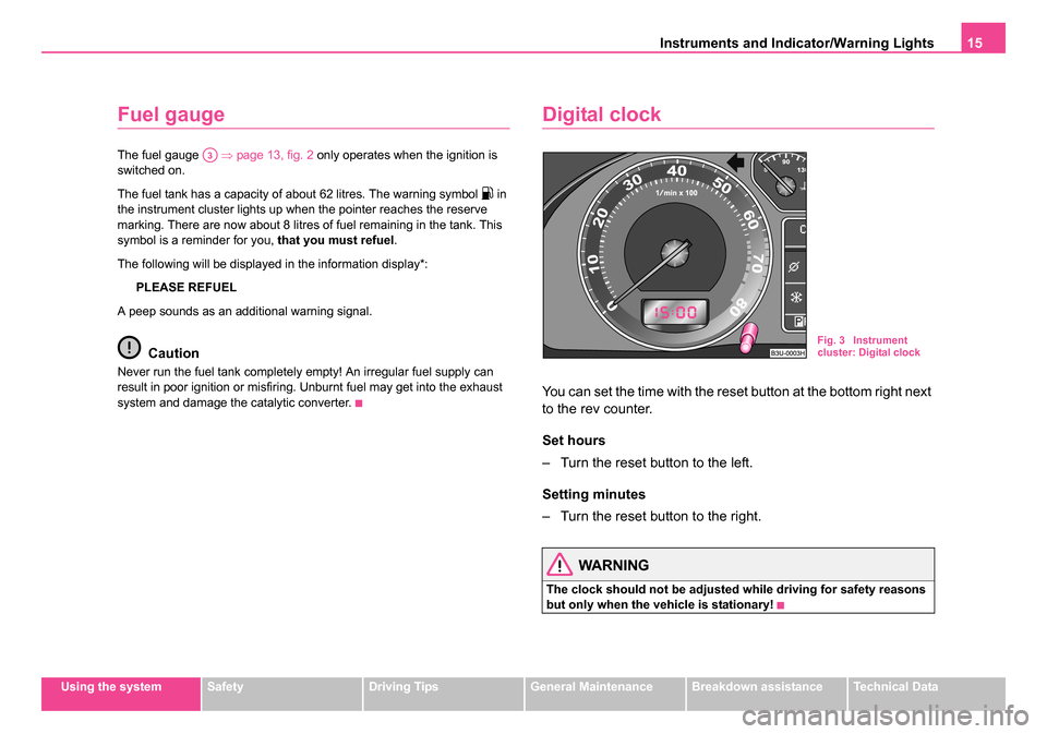
Digital clock
You can set the time with the reset button at the bottom right next
to the rev counter.
Set hours
– Turn the reset button to the left.
Setting minutes
– Turn the reset button to the right.
WARNING
The clock should not be adjusted while driving for safety reasons
but only when the vehicle is stationary!
A3
Fig. 3 Instrument
cluster: Digital clock
s3ec.book Seite 15 Montag, 2. Mai 2005 3:42 15
Page 18 of 281
Instruments and Indicator/Warning Lights17
Using the systemSafetyDriving TipsGeneral MaintenanceBreakdown assistanceTechnical Data
Depending on the equipment installed in the vehicle, the information
appears in the display of the counter for distance driven or in the informa-
tion display
⇒page 16, fig. 5 .
Service Interval Display
If the due date for the service is reached, the following text appears after
switching on the ignition:
in the display of the trip counter Service 1 500 km
in information display
SERVICE in 1500 km
Prior to the due date for the service the kilometre readout decreases in
steps of 100 km. As soon as the due date for the service is reached, the
following text appears:
in the display of the trip counter Service
in information display SERVICE NOW
The display disappears within 20 seconds after starting the engine. The
trip counter is also displayed after pressing the reset button of the trip
counter (for more than 1 second).
Resetting Service Interval Display
We recommend having this resetting performed by a specialist garage.
Specialist garage:
•resets the memory of the display after the appropriate inspection,
•makes an entry in the Service schedule,
•affix the sticker with the entry of the following service interval to the
side of the dash panel on the driver's side. It is also possible for you to reset the Service Interval Display with the
reset button
⇒page 16, fig. 5 as follows (does not apply to models
with fixed service intervals - QG2).
•Switch off the ignition (if not already off), press the reset button and
hold it down.
•Switch the ignition on and release the reset button . The text
Service or service now appears in the display.
•Turn the button for resetting the clock to the right - the display is
reset.
Caution
We recommend that you do not reset the Service Interval Display yourself
otherwise this can result in the service interval display being incorrectly
set, which may also result in problems with operation of your vehicle.
Note
•Never reset the display between service intervals otherwise this may
result in incorrect readouts.
•information is retained in the Service Interval Display also after the
battery of the vehicle is disconnected.
•it is necessary to re-code the Service Interval Display if a new instru-
ment cluster is installed during repair work. This work is carried out by a
specialist garage.
•After resetting the display with flexible service intervals (QG1) using
the reset button , the data displayed are the same as for a car with fixed
service intervals (QG2). We therefore recommend having the Service
Interval Display reset only by a Škoda dealer who is familiar with the
procedure for resetting the display with a vehicle system tester.
•Please refer to the brochure Service schedule for extensive informa-
tion about the service intervals.
AB
AB
AB
AA
AB
s3ec.book Seite 17 Montag, 2. Mai 2005 3:42 15
Page 20 of 281
Instruments and Indicator/Warning Lights19
Using the systemSafetyDriving TipsGeneral MaintenanceBreakdown assistanceTechnical Data
The data of the single-trip memory (memory 1) is shown if a
1 appears in
the display. A 2 shown in the display means that data relates to the total
distance memory (memory 2).
Switching of the memory takes place when the button ⇒fig. 8 .
Single-trip memory (memory 1)
The single-trip memory collates the driving information from the moment
the ignition is switched on until it is switched off. New data will also flow
into the calculation of the current driving information if the trip is continued
within 2 hours after switching off the ignition. The memory will be is auto-
matically erased, on the other hand, if the trip is interrupted for more than
2 hours.
Total-trip memory (memory 2)
The total distance driven memory gathers data from any number of indi-
vidual journeys up to a total of 99 hours and 59 minutes driving or 9.999
kilometres driven. The memory is deleted when either of these limits is
reached and the calculation starts from anew.
The total-trip memory will not, contrary to the single-trip memory, be
deleted after a period of interruption of driving of 2 hours.
Note
All information in the memory is erased if the battery of the vehicle is
disconnected.
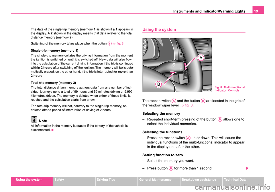
Using the system
The rocker switch and the button are located in the grip of
the window wiper lever ⇒fig. 8 .
Selecting the memory
– Repeated short-term pressing of the button allows one to select the individual memories.
Selecting the functions
– Press the rocker switch up or down. This will cause the individual functions of the multi-functional indicator to appear
in the display one after the other.
Setting function to zero
– Select the memory you want.
– Press button for more than 1 second.
AB
Fig. 8 Multi-functional
indicator: Controls
AAAB
AB
AA
AB
s3ec.book Seite 19 Montag, 2. Mai 2005 3:42 15
Page 22 of 281

Instruments and Indicator/Warning Lights21
Using the systemSafetyDriving TipsGeneral MaintenanceBreakdown assistanceTechnical Data
The display appears in litres/hour if the vehicle is stationary or driving at a
low speed.
Average fuel consumption
The average fuel consumption since the memory was last erased is
shown in the display in litres/100 km
⇒page 18. This information can help
you to adapt your style of driving to the fuel consumption you wish to
achieve.
If you wish to determine the average fuel consumption over a certain
period of time you must first erase the memory at the start of the new
measurement using the button ⇒page 19, fig. 8 . A zero appears in
the display for the first 300 m you drive after erasing the memory.
The indicated value will be updated every 30 metres while you are driving.
Note
The amount of fuel consumed will not be indicated.
Driving time
The driving time which has elapsed since the memory was last erased,
appears in the display ⇒page 18. If you wish to calculate the driving time
from a particular time of day you must first erase the memory at this
moment in time by pressing the button ⇒page 19, fig. 8 .
The maximum time indicated in both switch positions is 99 hours and 59
minutes. The indicator is set back to null if this period is exceeded.
Distance driven
The distance driven since the memory was last erased appears in the
display ⇒page 18. If you wish to calculate the distance driven from a
particular time of day you must first erase the memory at this moment in
time by pressing the button ⇒page 19, fig. 8 .
The maximum distance indicated in both switch positions is 9 999 km. The
indicator is set back to null if this period is exceeded.
Average speed
The average speed since the memory was last erased is shown in the
display in km/hour ⇒page 18. If you wish to determine the average speed
over a certain period of time you must first erase the memory at the start
of the new measurement using the button ⇒page 19, fig. 8 .
A zero appears in the display for the first 100 m you drive after erasing the
memory.AB
AB
AB
AB
s3ec.book Seite 21 Montag, 2. Mai 2005 3:42 15
Page 24 of 281

Instruments and Indicator/Warning Lights23
Using the systemSafetyDriving TipsGeneral MaintenanceBreakdown assistanceTechnical Data
Menu
– You can activate the menu by pressing the rocker switch
⇒fig. 11 for more than 1 second. – You can select the menu through the rocker switch . The
selected information is displayed after pressing the button
for a short time or after releasing the rocker switch (after
about 4 seconds).
You can select the following information (depending on the equipment
installed on the vehicle):
After selecting the menu DISPLAY OFF the display is switched off. Press
rocker switch for at least 1 second to switch the display on again.
The Information CAR STATUSflashes in the menu if there is something
which is not in proper order on the vehicle (e.g. warning of a low fuel level).
The first warning will be displayed after switching over to CAR STATUS.
You can then display other operating conditions afterwards using the
switch-over function (such as water level low).
Fig. 10 Information
display: Menu
Fig. 11 Information
display: Controls
AA
TRIP COMPUTER (AUTO COMPUTER)⇒ page 18
CAR STATUS⇒page 24
DISPLAY OFF
NAVIGATION⇒page 27
AA
AB
AA
AA
s3ec.book Seite 23 Montag, 2. Mai 2005 3:42 15