sensor SKODA SUPERB 2006 1.G / (B5/3U) Owner's Manual
[x] Cancel search | Manufacturer: SKODA, Model Year: 2006, Model line: SUPERB, Model: SKODA SUPERB 2006 1.G / (B5/3U)Pages: 281, PDF Size: 12.67 MB
Page 27 of 281

Instruments and Indicator/Warning Lights
26
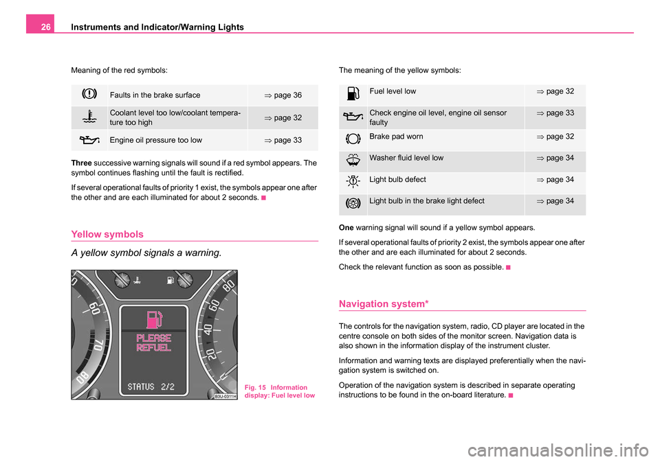
Meaning of the red symbols:
Three successive warning signals will sound if a red symbol appears. The
symbol continues flashing until the fault is rectified.
If several operational faults of priority 1 exist, the symbols appear one after
the other and are each illuminated for about 2 seconds.
Yellow symbols
A yellow symbol signals a warning.
The meaning of the yellow symbols:
One warning signal will sound if a yellow symbol appears.
If several operational faults of priority 2 exist, the symbols appear one after
the other and are each illuminated for about 2 seconds.
Check the relevant function as soon as possible.
Navigation system*
The controls for the navigation system, radio, CD player are located in the
centre console on both sides of the monitor screen. Navigation data is
also shown in the information display of the instrument cluster.
Information and warning texts are displayed preferentially when the navi-
gation system is switched on.
Operation of the navigation system is described in separate operating
instructions to be found in the on-board literature.
Faults in the brake surface⇒ page 36
Coolant level too low/coolant tempera-
ture too high⇒page 32
Engine oil pressure too low⇒page 33
Fig. 15 Information
display: Fuel level low
Fuel level low⇒page 32
Check engine oil level, engine oil sensor
faulty⇒page 33
Brake pad worn⇒page 32
Washer fluid level low⇒page 34
Light bulb defect⇒page 34
Light bulb in the brake light defect⇒page 34
NKO B5 20.book Page 26 Monday, July 3, 2006 2:09 PM
Page 34 of 281

Instruments and Indicator/Warning Lights33
Using the systemSafetyDriving TipsGeneral MaintenanceBreakdown assistanceTechnical Data
A peep sounds as an additional warning signal.
The following text will be displayed in the information display*:
PLEASE REFUEL
Engine oil
The warning light lights up red (low oil pressure)
The warning light comes on for a few seconds 2) when the ignition is
switched on.
Stop the vehicle and switch the engine off if the warning light does not
go off after the engine has started or flashes while driving. Check the oil
level and top up with oil as necessary ⇒ page 223.
3 peeps sound as an additional warning signal.
Do not continue your journey if for some reason it is not possible under
the conditions prevailing to top up with oil. Keep the engine switched off
and obtain professional assistance from a specialist garage, otherwise it
could lead to severe engine damage.
Do not drive any further if the warning light remains on even if the oil is
at the correct level. Do not run the engine not at idling speed either.
Contact the nearest specialist garage to obtain professional assistance.
The following text will be displayed in the information display*:
STOP! OIL PRESS. STOP MOTOR! SERVICE MANUAL (STOP! OIL
PRESSURE STOP ENGINE! OWNER'S MANUAL) The warning light
lights up yellow* (oil quantity too low)
If the warning light lights up yellow, there is not the correct quantity of oil
in the engine. Check as soon as possible the oil level or top up
⇒ page 223 with engine oil.
A peep sounds as an additional warning signal.
The following text will be displayed in the information display*:
CHECK OIL LEVEL
The warning light will go out if the bonnet is left open for more than 30
seconds. If no engine oil has been replenished, the warning light will come
on again after driving about 100 km.
The warning light
flashes yellow* (engine oil level sensor faulty)
A fault on the engine oil level sensor is indicated additionally by an audible
signal and the warning light coming on several times after the ignition has
been switched on.
In this case have the engine inspected without delay by a specialist
garage.
The following text will be displayed in the information display*:
OIL SENSOR WORKSHOP!
WARNING
•If you must stop for technical reasons, then park the vehicle at
a safe distance from the traffic and switch off the engine and switch
on the hazard warning light system ⇒page 59.
•The red oil pressure light is not an oil le vel indicator! One
should therefore check the oil level at regular intervals, preferably
after every refueling stop.
2)The warning light on vehicles fitted with information display does not come on
after switching the ignition on, but only if a fault exists or the engine oil level is too
low.
NKO B5 20.book Page 33 Monday, July 3, 2006 2:09 PM
Page 43 of 281

Unlocking and locking
42
Safe securing
The central locking system is equipped with a safe securing system.
Locking the vehicle from the outside causes the door locks to be automat-
ically blocked. It is not possible to pull out the locking buttons. The indi-
cator light in the driver's door flashes. It is not possible to open the doors
with the door handle either from the inside or from the outside. This acts
as an effective deterrent for attempts to break into your vehicle.
You can deactivate the safe securing system. This is done by locking the
vehicle with the key or radio-operated key twice within 2 seconds.
Deactivating the safe securing system means that the warning light next
to the securing knob in the driver's door will not flash. This is not the case,
however, for an activated anti-theft alarm system* since the indicator light
is showing that the system is active ⇒page 48.
The safe securing system is again activated the next time the vehicle is
unlocked and locked again.
The doors can be opened from the inside if the vehicle is locked and the
safe securing system is deactivated:
•The door is unlocked by actuating the door-opening lever.
•The door opens upon actuating the door-opening lever again.
WARNING
If the vehicle is locked from the outside and the safe securing
system is activated, there must not be any person and animals in
the vehicle as it is then not possible to open either a door or a
window from the inside. The locked doors make it more difficult for
rescuers to get into the vehicle in an emergency - hazard!
Note
The anti-theft alarm system is also armed when the car is closed without
activating the safe securing system. In this case, always switch off the
interior monitoring sensor* ⇒page 49 first of all to avoid an alarm being
triggered unintentionally.
Unlocking the vehicle using the key
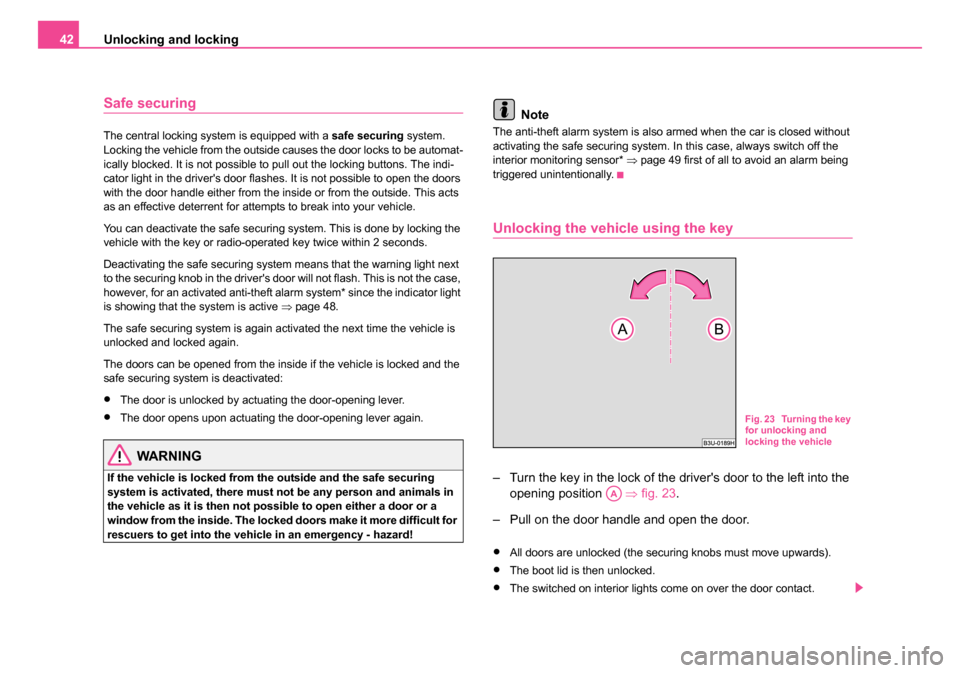
– Turn the key in the lock of the driver's door to the left into the opening position ⇒fig. 23 .
– Pull on the door handle and open the door.
•All doors are unlocked (the securing knobs must move upwards).
•The boot lid is then unlocked.
•The switched on interior lights come on over the door contact.
Fig. 23 Turning the key
for unlocking and
locking the vehicle
AA
NKO B5 20.book Page 42 Monday, July 3, 2006 2:09 PM
Page 63 of 281

Lights and Visibility
62
Rear interior lighting
The lights with interior monitoring sensors ⇒fig. 42 are actuated by
moving the switch to the symbol , O or to the middle position . The lights without interior monitoring sensors
⇒fig. 43 are actuated by
pressing the glass on the symbol
O or by switching to the middle posi-
tion .
The functions are the same as for the interior lighting at the front of the car
⇒ page 61.
Luggage compartment light
The light is located at the top side of the luggage compartment.
The lighting ⇒fig. 44 comes on automatically when the boot lid is opened.
The luggage compartment lighting will switch off again automatically if the
boot lid remains open for more than about 60 minutes.
Fig. 42 The roof light
at the rear with interior
monitoring sensors
Fig. 43 The interior
light at the rear without
interior monitoring
sensors
Fig. 44 Luggage
compartment: Lighting
NKO B5 20.book Page 62 Monday, July 3, 2006 2:09 PM
Page 66 of 281

Lights and Visibility65
Using the systemSafetyDriving TipsGeneral MaintenanceBreakdown assistanceTechnical Data
Windshield wiper and wash system
Windshield wiper
You can operate the windscreen wipers and automatic
wipe/wash using the windscreen wiper lever.
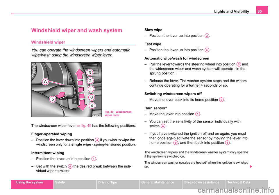
The windscreen wiper lever ⇒fig. 49 has the following positions:
Finger-operated wiping
– Position the lever down into position if you wish to wipe the windscreen only for a single wipe - spring-tensioned position.
Intermittent wiping
– Position the lever up into position .
– Set with the switch the desired break between the indi- vidual wiper strokes Slow wipe
– Position the lever up into position .
Fast wipe
– Position the lever up into position .
Automatic wipe/w
ash for windscreen
– Pull the lever towards the steering wheel into position and the widescreen wiper and wash system will operate - in the
sprung position.
– Release the lever. The washer system stops and the wipers
continue operating for a further 4 seconds or so.
Switching windscreen wipers off
– Move the lever back into its home position .
Rain sensor*
– Move the lever into position .
– You can set the sensitivity of the sensor individually with switch .
– If you have switched the ignition off and on again, you must then once again activate the sensor by moving the lever into
home position , and then back into position .
The windscreen wipers and the windscreen washer system only operate
if the ignition is switched on.
The windscreen washer nozzles are heated* when the ignition is switched
on.
Fig. 49 Windscreen
wiper lever
A4
A1
AA
A2
A3
A5
A0
A1
AA
A0A1
NKO B5 20.book Page 65 Monday, July 3, 2006 2:09 PM
Page 67 of 281

Lights and Visibility
66
The rain sensor* automatically regulates the break between the individual
wiper strokes depending on the intensity of the rain.
Top up with wash liquid ⇒page 233.
WARNING
•Properly maintained windscreen wiper blades are essential for
clear visibility and safe driving ⇒page 67.
•Do not use the windscreen washer system at low temperatures,
without heating the windscreen beforehand. Otherwise the window
cleaner could freeze on the windscreen and restrict the view to the
front.
•The rain sensor only operates as a support. The driver is not
released from the responsibility to set the function of the wind-
screen wipers manually dependi ng on the visibility conditions.
Caution
In frosty weather, please first of all check whether the windscreen wiper
blades are not frozen to the windscreen before switching them on.
Switching on windscreen wipers when the blades are frozen to the wind-
screen may result in damage both to the blades and the motor of the wind-
screen wipers!
Headlight cleaning system*
The headlight lenses are cleaned, when low beam or main beam are
switched on by holding ⇒page 65 the lever for about 2 seconds in the
position .
The headlight washer nozzles are moved forward out of the bumper by the
water pressure for cleaning the headlights.
You should remove stubborn dirt (such as insect residues) from the head-
light lenses at regular intervals, for example when refuelling. Please refer
to the following guidelines ⇒page 209, “The headlight lenses”.
You should remove any snow from the fixtures of the washer nozzles and
clear ice in winter with a de-icing spray in order to ensure proper operation
of the cleaning system.
Fig. 50 Headlight with
washer nozzle
extended
A5
NKO B5 20.book Page 66 Monday, July 3, 2006 2:09 PM
Page 69 of 281

Lights and Visibility
68
Automatic dimming interior mirror*
Switching on the automatic dimming
– Press the button - the warning light lights up ⇒fig. 52.
Switching off the automatic dimming
– Press again the button - the warning light goes out .
If the automatic dimming is switched on, the mirror dims automatically
depending on the light striking the mirror from the rear. The mirror has no
lever on the bottom edge of the mirror. When the interior lights are
switched on or the reverse gear is engaged, the mirror always moves back
into the basic position.
Note
•Automatic mirror dimming operates only properly if the sun screen* for
the rear window is not in use or the light striking the rear of the interior
rear-view mirror is not affected by other objects.
•Do not affix any stickers in front of the light sensor, so that you do not
impair the automatic dimming function or put it out of operation.
Exterior mirror with entry lighting*
The lighting is positioned on the bottom edge of the exte-
rior mirror.
The light beam is aimed at the entry area of the front doors after the car is
unlocked.
The light comes on after the doors have been locked or on opening the
front door. The lighting goes out about 30 seconds after the doors are
closed or if the ignition is switched on.
If the doors remain open, the lighting goes out automatically after about
10 minutes provided the ignition is not switched on.
Fig. 52 Automatic
dimming interior mirror
ABAA
ABAA
NKO B5 20.book Page 68 Monday, July 3, 2006 2:09 PM
Page 116 of 281

Heating and air conditioning system 115
Using the systemSafetyDriving TipsGeneral MaintenanceBreakdown assistanceTechnical Data
The buttons
Defrosting the windscreen
The displays Display of blower stages
Display of outside temperature, here: +11 °C
Defrosting the windscreen
Recirculated air mode
Direction of air flow
Display of selected inside temperature, here: +22 °C
Display for:
− Automatic mode ( AUTO) or
− Cooling system switched off ( ECON) or
− Climatronic switched off ( OFF)
The buttons Automatic mode
Recirculated air mode
Button for:
−Reducing blower speed or
− Switching off Climatronic ( OFF)
Increasing blower speed button or switching Climatronic on
Air flow button to chest (ventilation mode)
Air flow button to footwell at front and rear (heating mode)
Button for decreasing temperature
Button for increasing temperature
Button for switching off cooling system
The sensor Interior temperature sensor
Buttons , and can also be pressed in combination.
Automatic mode
The automatic mode is used in order to maintain a
constant temperature and to demist the windows in the
interior of the car.
Switching automatic mode on
– Set a temperature between +18 °C (64 °F) and +29 °C (86 °F).
– Move the air outlet vents 3 and 4 ⇒ page 118, fig. 111
upwards
– Press the button .
When the automatic mode is operating, AUTO appears in the display.
Automatic mode operates only within the control temperature range from
+18 °C (64 °F) up to 29 °C (86 °F). If you select the temperature below
+18 °C (64 °F), LO appears in the display. If you select a temperature
higher than + 29 °C (86 °F), HI appears in the display. In both limit posi-
tions the Climatronic operates at maximum cooling or heating capacity,
respectively. The temperature is not controlled in this case.
If you press when the automatic mode is operating a desired button
(except buttons 15 and 16 ), the automatic mode is switched off.
ECON mode
The cooling system is switched off in the ECON mode -
heating and ventilation are regulated automatically.
Switching ECON mode on
– Press the button .
A1
A2
A3
A4
A5
A6
A7
A8
A9AUTO
A10
A11
A12
A13
A14
A15
A16
A17ECON
A18
A1A13A14
AUTO
ECON
NKO B5 20.book Page 115 Monday, July 3, 2006 2:09 PM
Page 127 of 281

Starting-off and Driving
126
Caution
After the car has come to a stop, always first of all apply the handbrake
firmly before then additionally engaging a gear (manual gearbox) or
moving the selector lever into position P (automatic gearbox).
Parking aid*
The parking aid provides a warning of obstacles behind
the vehicle.
The audible parking aid determines the distance between the rear bumper
and an obstacle located behind the vehicle with the aid of ultrasound
sensors. The sensors are integrated in the rear bumper. Range of sensors
The clearance warning begins at a distance of about 160 cm from the
obstacle (area
⇒fig. 119 ). The interval between the warning signals
becomes shorter as the clearance is reduced.
A continuous tone sounds from a clearance of just 30 cm (Bereich ) -
danger area. From this moment on do not continue driving in the
selected direction or the direction from where the obstacle is
reported!
Activating
The parking aid is activated automatically when reverse gear is engaged
and the ignition is turned on. This is confirmed by a brief acknowledge-
ment signal.
Deactivating
The parking aid is deactivated by removing the reverse gear.
WARNING
•The parking aid is not a substitute for the driver paying proper
attention and it is always the driver's responsibility to take care
when parking the vehicle or carrying out similar manoeuvres.
•You should therefore satisfy yourself, before reversing, that
there is no small obstacle, such as a rock, thin post, trailer drawbar
etc., behind your vehicle. Such an obstacle might not be within the
range detected by the sensors.
Note
•The parking aid does not operate if you are towing a trailer (applies to
models which feature a factory-fitted towing device*).
•If a warning signal sounds for about 3 seconds after switching the igni-
tion on and engaging reverse gear, and there is no obstacle close to your
Fig. 119 Parking aid:
Detection range of rear
sensors
AA
AB
NKO B5 20.book Page 126 Monday, July 3, 2006 2:09 PM
Page 128 of 281

Starting-off and Driving127
Using the systemSafetyDriving TipsGeneral MaintenanceBreakdown assistanceTechnical Data
car, this indicates a system fault. Have the fault rectified by a specialist
workshop.
•The sensors must be kept clean and free of ice to enable the parking
aid to operate properly.
Front and rear parking aid*
The parking aid provides a warning of obstacles in front
and behind the vehicle.
The audible parking aid determines the distance between the front or rear
bumper and an obstacle with the aid of ultrasound sensors. The sensors
are integrated in the front and rear bumper. The signal tones for the front
parking aid sound lower than for the rear parking aid.
Range of sensors
The distance warning begins at a distance of about 60 cm from the
obstacle in front of the vehicle (area ⇒fig. 121 ) and about 160 cm
from the obstacle behind the vehicle (area ⇒page 126, fig. 119 ). The
interval between the warning signals becomes shorter as the clearance is
reduced.
A continuous tone sounds from a clearance of just 30 cm (Bereich ) -
danger area. From this moment on do not continue driving in the
selected direction or the direct ion from where the obstacle is
reported!
Activating
The parking aid is activated when the reverse gear is engaged and the
ignition is turned on or by pressing the button ⇒fig. 120 - the symbol
Fig. 120 Activating the
parking aid
Fig. 121 Parking aid:
Detection range of the
front sensors
AAAA
AB
NKO B5 20.book Page 127 Monday, July 3, 2006 2:09 PM