SKODA SUPERB 2009 2.G / (B6/3T) User Guide
Manufacturer: SKODA, Model Year: 2009, Model line: SUPERB, Model: SKODA SUPERB 2009 2.G / (B6/3T)Pages: 294, PDF Size: 21.33 MB
Page 11 of 294
Cockpit
10
•
Cars with factory-fitted radio or naviga
tion system are supplied with separate
instructions for operating such equipment.•
The arrangement of the controls and switches and the location of some items
on right-hand drive models may differ from that shown in
⇒page 8, fig. 1
. The
symbols on the controls and switches are the same as for left-hand drive models.s2dk.1.book Page 10 Wednesday, April 8, 2009 12:23 PM
Page 12 of 294
The brief instruction
11
Using the system
Safety
Driving Tips
General Maintenance
Breakdown assistance
Technical Data
The brief instructionBasic functions and im
portant information
Introduction The chapter of the brief instruction is only used as a quick reference of the most important operating elem
ents of the vehicle. It is neces-
sary to observe all the informat
ion which is contained in the
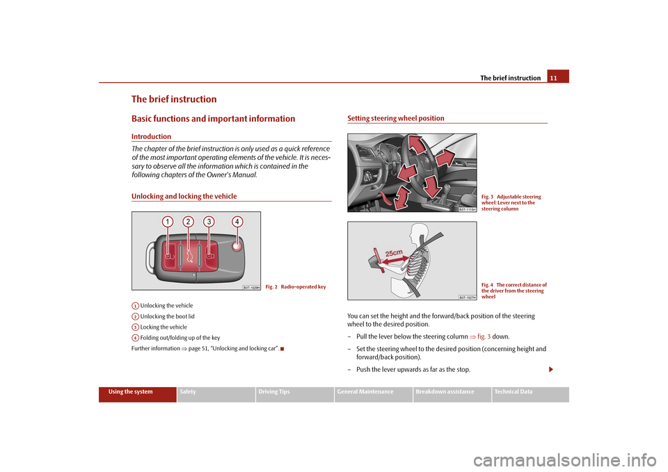
following chapters of the Owner's Manual.Unlocking and locking the vehicle Unlocking the vehicle Unlocking the boot lid Locking the vehicle Folding out/folding up of the keyFurther information
⇒page 51, “Unlocking and locking car”.
Setting steering wheel positionYou can set the height and the forwar
d/back position of the steering
wheel to the desired position. – Pull the lever below the steering column
⇒
fig. 3
down.
– Set the steering wheel to the desired position (concerning height and
forward/back position).
– Push the lever upwards as far as the stop.
Fig. 2 Radio-operated key
A1A2A3A4
Fig. 3 Adjustable steering wheel: Lever next to the steering columnFig. 4 The correct distance of the driver from the steering wheel
s2dk.1.book Page 11 Wednesday, April 8, 2009 12:23 PM
Page 13 of 294
The brief instruction
12
Further information
⇒page 117, “Setting steering wheel position”.
WARNING
•
Adjust the steering wheel
so that the distance
between the steering
wheel and your chest is at least 25 cm
⇒page 11, fig. 4
. Not maintaining this
minimum distance will mean that the airb
ag system will not be able to prop-
erly protect you - hazard!•
You must not adjust the steering wh
eel when the vehicle is moving!
•
For sa fe t y re as ons the l e ve r m us t a lw ay s b e f irm l y pu she d up t o a vo id th e
steering wheel altering its position uni
ntentionally when driving - risk of
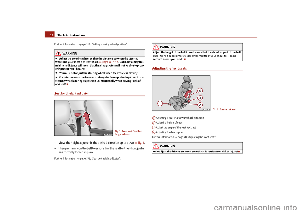
accident!Seat belt height adjuster– Move the height adjuster in the desired direction up or down
⇒
fig. 5
.
– Then pull firmly on the belt to ensure that the seat belt height adjuster
has correctly locked in place.
Further information
⇒page 171, “Seat belt height adjuster”.
WARNING
Adjust the height of the belt in such a way that the shoulder part of the belt is positioned approximately across the middle of your shoulder - on no account across your neck!Adjusting the front seats Adjusting a seat in a forward/back direction Adjusting height of seat Adjust the angle of the seat backrest Adjusting lumbar supportFurther information
⇒page 78, “Adjusting the front seats”.
WARNING
Only adjust the driver seat
when the vehicle is stationary - risk of injury!
Fig. 5 Front seat: Seat belt height adjuster
Fig. 6 Controls at seat
A1A2A3A4
s2dk.1.book Page 12 Wednesday, April 8, 2009 12:23 PM
Page 14 of 294
The brief instruction
13
Using the system
Safety
Driving Tips
General Maintenance
Breakdown assistance
Technical Data
Electric exterior mirror adjustmentFurther information
⇒page 13, “Electric exteri
or mirror adjustment”.
Switching lights on and offFurther information
⇒page 60, “Switching lights on and off
”.
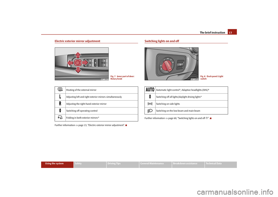
Heating of the external mirror
Adjusting left and right exterior mirrors simultaneously
Adjusting the right-hand exterior mirror
Switching off operating control
Folding in both exterior mirrors*
Fig. 7 Inner part of door: Rotary knob
Automatic light control*, Adaptive headlights (AHL)*
Switching off all lights/daylight driving lights*
Switching on side lights
Switching on the low beam and main beam
Fig. 8 Dash panel: Light switch
s2dk.1.book Page 13 Wednesday, April 8, 2009 12:23 PM
Page 15 of 294
The brief instruction
14
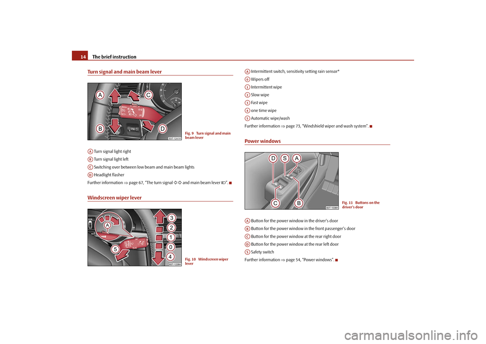
Turn signal and main beam lever Turn signal light right Turn signal light left Switching over between low beam and main beam lights Headlight flasherFurther information
⇒page 67, “The turn signal
and main beam lever
”.
Windscreen wiper lever
Intermittent switch, sensitivity setting rain sensor* Wipers off Intermittent wipe Slow wipe Fast wipe one time wipe Automatic wipe/washFurther information
⇒page 73, “Windshield wiper and wash system”.
Power windows Button for the power window in the driver's door Button for the power window in the front passenger's door Button for the power window at the rear right door Button for the power window at the rear left door Safety switchFurther information
⇒page 54, “Power windows”.
B3T-1241H
Fig. 9 Turn signal and main beam lever
AAABACAD
Fig. 10 Windscreen wiper lever
AAA0A1A2A3A4A5
Fig. 11 Buttons on the driver's door
AAABACADAS
s2dk.1.book Page 14 Wednesday, April 8, 2009 12:23 PM
Page 16 of 294
The brief instruction
15
Using the system
Safety
Driving Tips
General Maintenance
Breakdown assistance
Technical Data
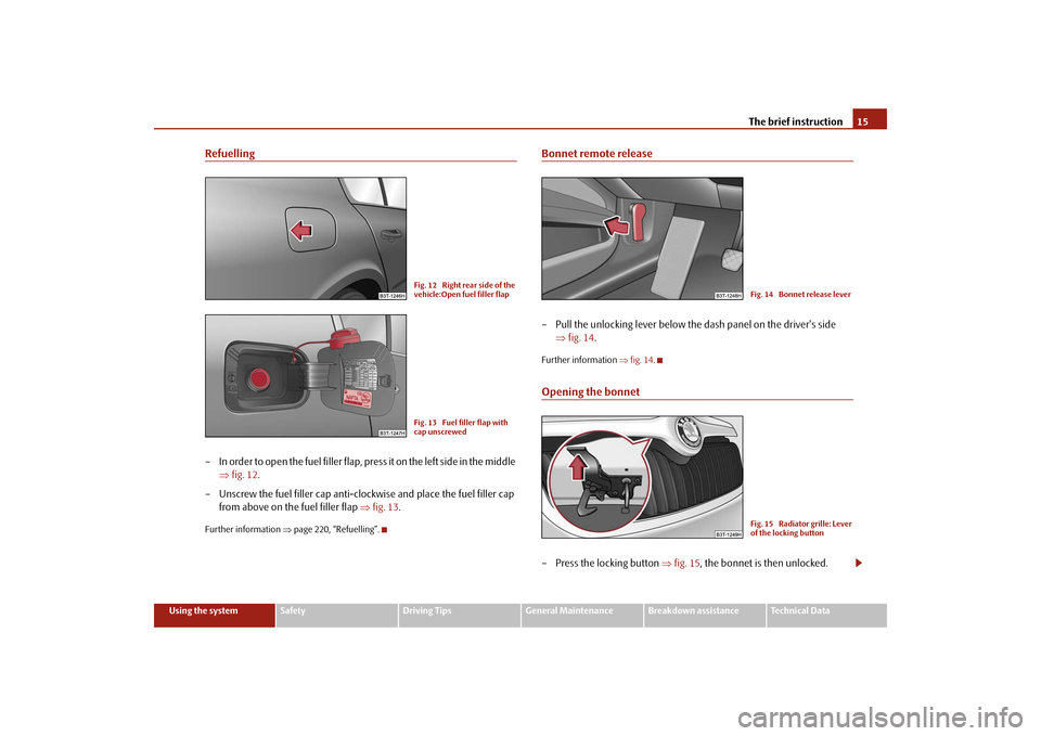
Refuelling– In order to open the fuel filler flap, press it on the left side in the middle
⇒
fig. 12
.
– Unscrew the fuel filler cap anti-cl
ockwise and place the fuel filler cap
from above on the fuel filler flap
⇒
fig. 13
.
Further information
⇒page 220, “Refuelling”.
Bonnet remote release– Pull the unlocking lever below the
dash panel on the driver's side
⇒
fig. 14
.
Further information
⇒fig. 14
.
Opening the bonnet– Press the locking button
⇒
fig. 15
, the bonnet is then unlocked.
Fig. 12 Right rear side of the vehicle:Open fuel filler flapFig. 13 Fuel filler flap with cap unscrewed
Fig. 14 Bonnet release leverFig. 15 Radiator grille: Lever of the locking button
s2dk.1.book Page 15 Wednesday, April 8, 2009 12:23 PM
Page 17 of 294
The brief instruction
16
– Grasp the bonnet at the bottom part
of the radiator grille and lift it
towards the top so that it is held
opened by the gas pressure support.
Further information
⇒page 222, “Opening and closing the bonnet.”.
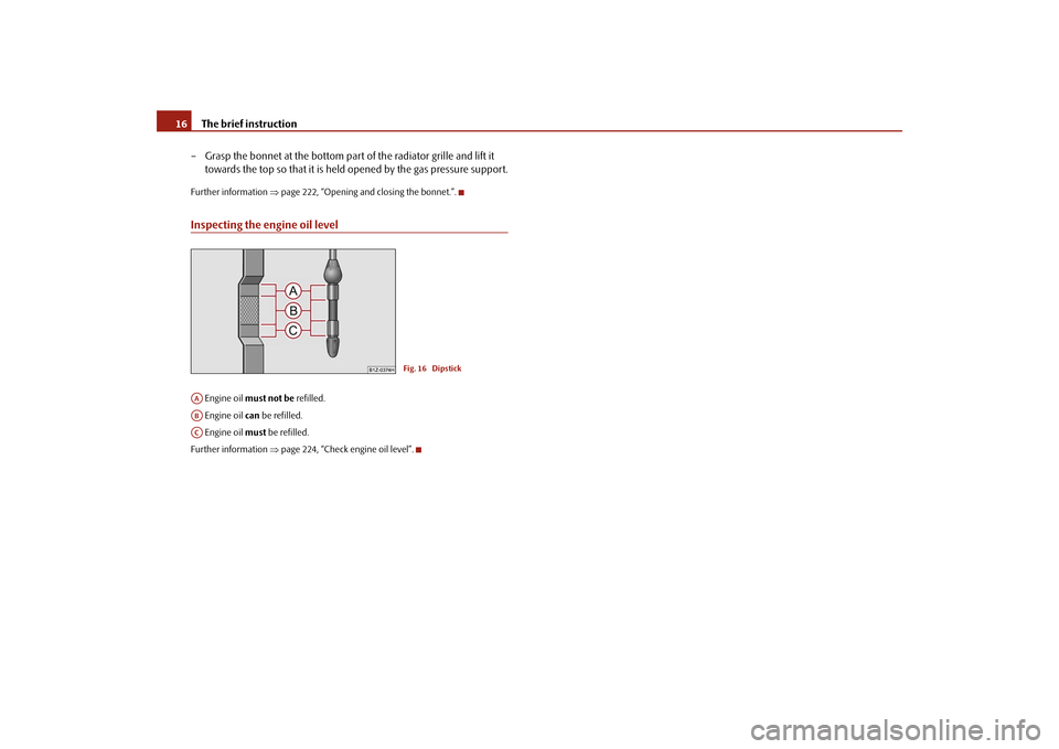
Inspecting the engine oil level Engine oil
must not be
refilled.
Engine oil
can
be refilled.
Engine oil
must
be refilled.
Further information
⇒page 224, “Check engine oil level”.
Fig. 16 Dipstick
AAABACs2dk.1.book Page 16 Wednesday, April 8, 2009 12:23 PM
Page 18 of 294
Instruments and Indicator/Warning Lights
17
Using the system
Safety
Driving Tips
General Maintenance
Breakdown assistance
Technical Data
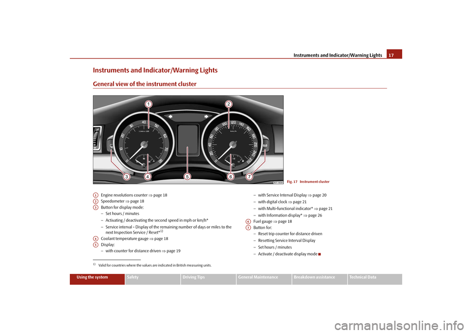
Instruments and Indicator/Warning LightsGeneral view of the instrument cluster
Engine revolutions counter
⇒page 18
Speedometer
⇒page 18
Button for display mode: − Set hours / minutes − Activating / deactivating the
second speed in mph or km/h*
− Service interval - Display of the remaining number of days or miles to the next Inspection Service / Reset*
1)
Coolant temperature gauge
⇒page 18
Display:− with counter for distance driven
⇒page 19
− with Service Interval Display
⇒page 20
− with digital clock
⇒page 21
− with Multi-functional indicator*
⇒page 21
− with Information display*
⇒page 26
Fuel gauge
⇒page 18
Button for: − Reset trip counter for distance driven − Resetting Service Interval Display − Set hours / minutes − Activate / deactivate display mode
Fig. 17 Instrument cluster
1)Valid for countries where the values are indicated in British measuring units.A1A2A3A4A5
A6A7
s2dk.1.book Page 17 Wednesday, April 8, 2009 12:23 PM
Page 19 of 294
Instruments and Indicator/Warning Lights
18
Engine revolutions counterThe red zone of the rev counter scale
⇒page 17, fig. 17
indicates the range in
which the engine control unit begins to li
mit the engine speed. The engine control
unit restricts the engine speed to the steady limit value. Shift into the next higher gear or select
the selector lever position D of the auto-
matic gearbox before reaching the red zone of the rev counter scale. Avoid high engine speeds during the driv
ing time and before the engine has been
warmed up to operating temperature
⇒page 201.
For the sake of the environment
Shifting up early helps you save fuel and reduce the operating noise of your vehicle.SpeedometerWarning against excessive speeds* An acoustic warning signal will sound when the vehicle speed exceeds 120 kilome- tres per hour. The acoustic warning signal
will switch off ag
ain when the vehicle
speed goes below this speed limit.
Note
This function is only valid for some countries.Coolant temperature gaugeThe coolant temperature gauge
⇒page 17, fig. 17
operates only when the igni-
tion is switched on. In order to avoid any damage to the engine
, please pay attentio
n to the following
notes regarding the temperature ranges:
Cold range If the pointer is in the left-hand area of the scale it means that the engine has not yet reached its operating temperature. Avoi
d running at high engine speeds, at full
throttle and at severe engine loads. The operating range The engine has reached its operating temperature as soon as the pointer moves into the mid-range of the scale. The pointe
r may also move further to the right at
high engine loads and high outside temper
atures. This is not critical provided the
warning symbol
in the instrument cluster does not flash.
If the symbol
in the instrument cluster flashes it means that either the coolant
temperature
is too high or the coolant
level
is too low. Observe the guidelines
⇒ page 38, “Coolant temperature/ Coolant quantity
”.
WARNING
Pay attention to the warning notes
⇒page 223, “Working in the engine
compartment” before opening the bonnet and inspecting the coolant level.
Caution
Additional headlights and other attached co
mponents in front of the fresh air inlet
impair the cooling efficiency of the coolant. There is then a risk of the engine over-heating at high outside temperatures and high engine loads!Fuel gaugeThe fuel gauge
⇒page 17, fig. 17
only operates when th
e ignition is switched
on. The fuel tank has a capacity of about 60 litres. The warning symbol
in the instru-
ment cluster lights up when the pointer reaches the reserve marking. There are now about 9 litres of fuel remaining in the tank. This symbol is a reminder for you,
that
you must refuel
.
A1
A4
A6
s2dk.1.book Page 18 Wednesday, April 8, 2009 12:23 PM
Page 20 of 294
Instruments and Indicator/Warning Lights
19
Using the system
Safety
Driving Tips
General Maintenance
Breakdown assistance
Technical Data
The following will be displayed in the information display*:
Please refuel!
An audible signal sounds as an additional warning signal.
Caution
Never run the fuel tank completely empty!
An irregular supply of fuel can lead to
irregular engine running.
Unburnt fuel may get into the exhaust system and
damage the catalytic converter.
Note
After filling up, it can occur that during
dynamic driving (e.g. numerous curves,
braking, driving downhill and climbing a st
eep hill) the fuel ga
uge indicates approx.
a fraction less. When stopping or during
less dynamic driving, the correct fuel
supply quantity is
indicated. This effect is not a fault.
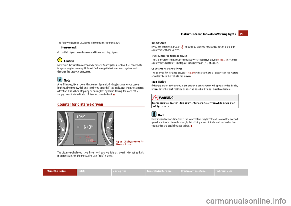
Counter for distance drivenThe distance which you have
driven with your vehicle is
shown in kilometres (km).
In some countries the measur
ing unit “mile” is used.
Reset button If you hold the reset button
⇒page 17 pressed for about 1 second, the trip
counter is set back to zero. Trip counter for distance driven The trip counter indicates the di
stance which you have driven
⇒fig. 18
since this
counter was last reset - in steps of 100 metres or 1/10 of a mile. Counter for distance driven The counter for distance driven
⇒fig. 18
indicates the total distance in kilometers
or miles which the vehicle has driven. Fau lt dis pla y If there is a fault in the instrument cluster,
a constant text will appear in the display
Error
. Have the fault rectified as soon as
possible by a specialist workshop.
WARNING
Never seek to adjust the trip counter for distance driven while driving for safety reasons!
Note
If vehicles which are fitted with the information display* the display of the second speed is activated in mph or km/h, this driving speed is indicated instead of the counter for the total distance driven.
Fig. 18 Display: Counter for distance driven
A7
s2dk.1.book Page 19 Wednesday, April 8, 2009 12:23 PM