engine SKODA SUPERB 2009 2.G / (B6/3T) Owner's Guide
[x] Cancel search | Manufacturer: SKODA, Model Year: 2009, Model line: SUPERB, Model: SKODA SUPERB 2009 2.G / (B6/3T)Pages: 294, PDF Size: 21.33 MB
Page 44 of 294
Unlocking and locking
43
Using the system
Safety
Driving Tips
General Maintenance
Breakdown assistance
Technical Data
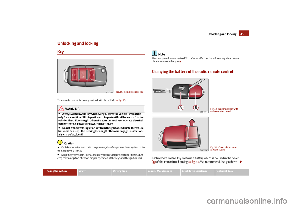
Unlocking and lockingKeyTwo remote control keys are provided with the vehicle
⇒fig. 36
.
WARNING
•
Always withdraw the key whenever you
leave the vehicle - even if it is
only for a short time. This is particularly important if children are left in the vehicle. The children might otherwise st
art the engine or operate electrical
equipment (e.g. power windows) - risk of injury!•
Do not withdraw the ignition key from the ignition lock until the vehicle
has come to a stop. The
steering lock might othe
rwise engage unintention-
ally - risk of accident!
Caution
•
Each key contains electronic components; therefore protect them against mois-
ture and severe shocks.•
Keep the groove of the keys absolutely clean as impurities (textile fibres, dust
etc.) have a negative effect on proper op
eration of the keys and the ignition lock.
Note
Please approach an authorised Škoda Servic
e Partner if you lose a key since he can
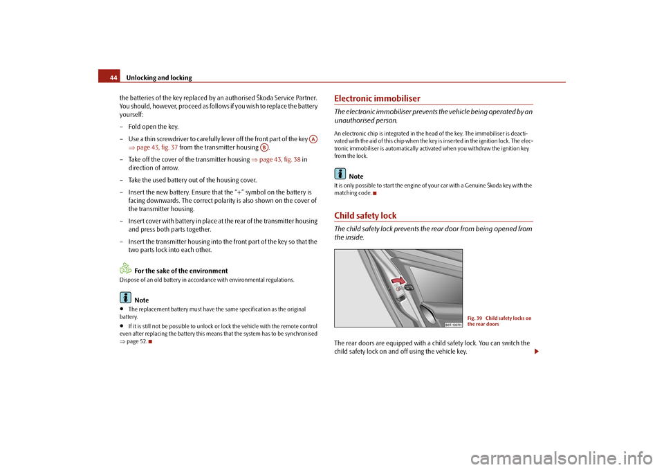
obtain a new one for you.Changing the battery of the radio remote controlEach remote control key contains a battery which is housed in the cover
of the transmitter housing
⇒
fig. 37
. We recommend that you have
Fig. 36 Remote control key
Fig. 37 Disconnect key with radio remote controlFig. 38 Cover of the trans-mitter housing
AB
s2dk.1.book Page 43 Wednesday, April 8, 2009 12:23 PM
Page 45 of 294
Unlocking and locking
44
the batteries of the key replaced by an authorised Škoda Service Partner. You should, however, proceed as follows if you wish to replace the battery yourself: – Fold open the key. – Use a thin screwdriver to carefully lever off the front part of the key
⇒
page 43, fig. 37
from the transmitter housing .
– Take off the cover of the transmitter housing
⇒
page 43, fig. 38
in
direction of arrow.
– Take the used battery out of the housing cover. – Insert the new battery. Ensure that the “+” symbol on the battery is
facing downwards. The correct polarity is also shown on the cover of the transmitter housing.
– Insert cover with battery in place at
the rear of the transmitter housing
and press both parts together.
– Insert the transmitter housing into the front part of the key so that the
two parts lock into each other. For the sake of the environment
Dispose of an old battery in accord
ance with environmental regulations.
Note
•
The replacement battery must have the same specification as the original
battery.•
If it is still not be possible to unlock or
lock the vehicle with the remote control
even after replacing the battery this means
that the system has to be synchronised
⇒ page 52.
Electronic immobiliserThe electronic immobiliser prevents
the vehicle being operated by an
unauthorised person.An electronic chip is integrated in the he
ad of the key. The i
mmobiliser is deacti-
vated with the aid of this chip when the key is inser ted in the ignition lock. The elec- tronic immobiliser is automatically activa
ted when you withdraw the ignition key
from the lock.
Note
It is only possible to start the engine of your car with a Genuine Škoda key with the matching code.Child safety lockThe child safety lock pr
events the rear door from being opened from
the inside.The rear doors are equipped with a child safety lock. You can switch the child safety lock on and off using the vehicle key.
AA
AB
Fig. 39 Child safety locks on the rear doors
s2dk.1.book Page 44 Wednesday, April 8, 2009 12:23 PM
Page 52 of 294
Unlocking and locking
51
Using the system
Safety
Driving Tips
General Maintenance
Breakdown assistance
Technical Data
The transmitter with the battery is housed
in the handle of the remote control key.
The receiver is located in the interior of the car. The operating range of the remote control is approx. 30 m. But this range of the remote control can be reduced if the batteries are weak. The remote control key has a fold-open key
bit which can be used
for unlocking and
locking the car manually and also for starting the engine. If a lost key is replaced or if the rece
iver unit has been repaired or a new unit
installed, it is then necessary for an authorised Škoda Service Partner to initialise the system. Only after this is it possible to again use the remote control.
Note
•
The remote control is automatically deac
tivated when the ignition is switched
on.•
The operation of the remote control may temporarily be affected by interfer-
ence from transmitters close to the car
and which operate in the same frequency
range (e.g. mobile phon
e, TV transmitter).
•
The battery must be replaced, ideally by
an authorised Škoda Service Partner, if
the central locking or anti-theft alarm system does react to the remote control at less than 3 metres away.•
If the driver door is opened, the vehi
cle cannot be locked using the remote
control.
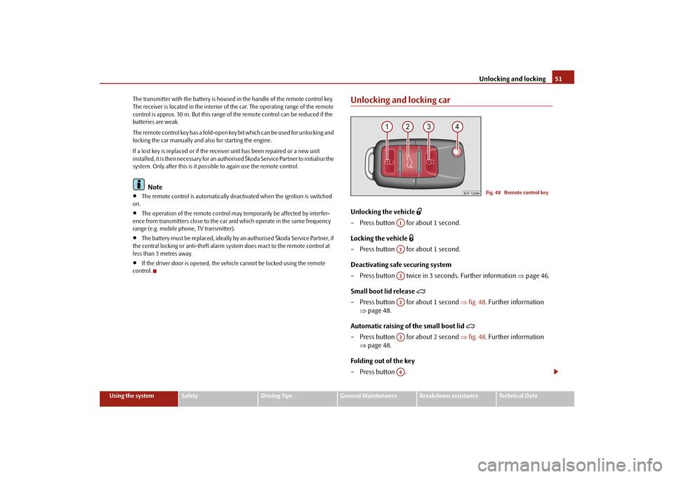
Unlocking and locking carUnlocking the vehicle
– Press button for about 1 second. Locking the vehicle
– Press button for about 1 second.Deactivating safe securing system – Press button twice in 3 seconds. Further information
⇒
page 46.
Small boot lid release
– Press button for about 1 second
⇒
fig. 48
. Further information
⇒
page 48.
Automatic raising of the small boot lid
– Press button for about 2 second
⇒
fig. 48
. Further information
⇒
page 48.
Folding out of the key –Press button .
Fig. 48 Remote control key
A1A3A2A2A2A4
s2dk.1.book Page 51 Wednesday, April 8, 2009 12:23 PM
Page 66 of 294
Lights and Visibility
65
Using the system
Safety
Driving Tips
General Maintenance
Breakdown assistance
Technical Data
•
the vehicle is stationary an
d the engine is running or
it moves with a speed of
maximum 40 km/h,•
the daylight driving lights are not switched on,
•
the low beam is switched on or th
e light switch is in the position
and the
intensity of the ambient light causes
the low beam to be switched on,
•
the fog lights are not switched on,
•
no reverse gear is engaged.Note
If you engage the reverse gear during the
active function “Corner”, both fog lights
illuminate.Rear fog light
Switching on the rear fog light – First of all turn the light switch into position
or
⇒
page 64,
fig. 57
.
– Pull the switch into position .The rear fog light warning light
⇒page 33 lights up in the instrument cluster
when the fog light is switched off. Only the rear fog light of the trailer lights up automatically when you are towing a trailer
using a factory-fitted towing device
which is fitted with the rear fog light.
The rear fog light is located in the rear light array on the driver's side.
Caution
The rear fog light should only be switched
on if visibility is
particularly poor
(conform with any varying legal provisions)
to avoid dazzling vehicles behind your
vehicle.
Instrument lighting
You can adjust the brightness
of the instrument lighting.
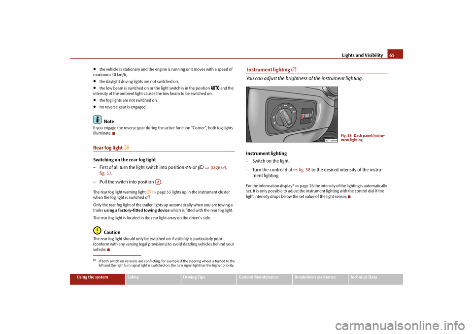
Instrument lighting – Switch on the light. – Turn the control dial
⇒
fig. 58
to the desired intensity of the instru-
ment lighting.
For the information display*
⇒page 26 the intensity of the lighting is automatically
set. It is only possible to adjust the inst
rument lighting with the control dial if the
light intensity drops below the set value of the light sensor.
8)If both switch on versions are conflicting, fo
r example if the steering wheel is turned to the
left and the right turn signal light is switched on, the turn signal light has the higher priority.
A2
Fig. 58 Dash panel: Instru-ment lighting
s2dk.1.book Page 65 Wednesday, April 8, 2009 12:23 PM
Page 72 of 294

Lights and Visibility
71
Using the system
Safety
Driving Tips
General Maintenance
Breakdown assistance
Technical Data
Rear window heater – You can switch the rear window heater on or off by pressing the switch
⇒
page 70, fig. 69
- the indicator light in the switch comes on or
goes out.
The windscreen and rear window heater only operates when the engine is running. The windscreen and rear window heater
switches
off automatically after 10
minutes.
For the sake of the environment
As soon as the window is de-iced or free from mist, the heating should be switched off. The reduced current consumption will have a favourable effect on fuel economy
⇒page 205, “Saving electricity”.
Note
•
If the on-board voltage drops, the wi
ndscreen or rear window heater is
switched off automatica
lly, in order to provide sufficient electrical energy for the
engine control.•
The position and the shape of the switch for rear window heater can differ
depending on the equipment installed in the vehicle.
Sun visorsYou can pull the sun visor for the driver or
front passenger out of the fixture and
swivel it toward the door in the direction of the arrow
⇒fig. 70
.
The vanity mirrors in the sun visors are provided with covers. When you slide open the cover in the direction of the arrow , the vanity mirror lighting in the headliner switches on automatically. It switches off again when you slide the cover closed or when you raise the sun visor.
WARNING
The sun visors must not be swivelled to the side windows into the deploy-ment area of the head airbags if any ob
jects, such as ball-point pens etc. are
attached to them. This might result in injuries to the occupants if the head airbag is deployed.
Fig. 70 Sun visor: swivelling outA1
A2
s2dk.1.book Page 71 Wednesday, April 8, 2009 12:23 PM
Page 77 of 294

Lights and Visibility
76
Switching on the automatic dimming – Press the button - the warning light lights up
⇒
page 75, fig. 75
.
Switching off the automatic dimming – Press again the button - the warning light goes out .If the automatic dimming is sw
itched on, the mirror dims
automatically
depending on the light striking the mirror
from the rear. The mirror has no lever on
the bottom edge of the mirror. When the interior lights are switched on or the reverse gear is engaged, the mirror alwa
ys moves back into the basic position.
Note
•
Automatic mirror dimming operates only pr
operly if the sun screen* for the rear
window in the housing on the luggage comp
artment cover is not in use or the light
striking the interior rear-view mirror
is not affected by other objects.
•
Do not affix any stickers in front of the li
ght sensor, so that you do not impair the
automatic dimming function or put it out of operation.•
If you switch off the automatic dimming interior rear-view mirror, also the exte-
rior mirror dimming
is switched off.
Exterior mirror with entry lighting* The lighting is positioned on the bo
ttom edge of the exterior mirror.
The light beam is aimed at the entry area of the front doors after the car is unlocked. The light comes on after the doors have been locked or on opening the front door. The lighting goes out about 30 seconds after
the doors are closed or if the ignition
is switched on. If the doors remain open, the lighting go
es out automatically after about 10 minutes
provided the ignition
is not switched on.
Exterior mirrorYou can adjust the exterior mirrors electrically*.The exterior mirror heater only oper
ates when the engine is running and
up to an outside temperature of +20 °C. Heating of the external mirror – Turn the rotary knob to position
⇒
fig. 76
.
Adjusting left and right exterior mirrors simultaneously – Turn the rotary knob to position
. The movement of the mirror surface
is identical to the movement of the rotary knob.
Adjusting the right-hand exterior mirror – Turn the rotary knob to position
. The movement of the mirror
surface is identical to the movement of the rotary knob.
Switching off operating control – Turn the rotary knob to position
.
Folding in both exterior mirrors* – Turn the rotary knob to position
.
AB
AA
AB
AA
Fig. 76 Inner part of door: Rotary knob
s2dk.1.book Page 76 Wednesday, April 8, 2009 12:23 PM
Page 87 of 294
Seats and Stowage
86
– With repeated pressing of the switch, the intensity of the heating is
down-regulated up to the switch-off. The intensity of the heating is indicated by the number of illuminated warning lights in the switch.
WARNING
If you have a subdued pain and/or temperature sensitivity, e.g. through medication, paralysis or because of chronic illness (e.g. diabetes), we recommend not to use the seat heating. This can lead to burns on the back, the posterior and the legs which are diff
icult to heal. If the seat heating is
used, we recommend to make regular br
eaks in your journey when driving
long distances, so that in specific cases as mentioned above the body can recuperate from the stress of the journey. Please consult your doctor, who can evaluate your specific condition.
Caution
•
You should not kneel on the seats or otherwise apply pressure at specific points
in order to avoid damaging the heating elements of the seat heaters.•
Do not use the seat heating if the seats are not occupied by persons or if objects
are fastened or stored on them, for exampl
e a child seat, a bag etc. A fault of the
heating elements in the seat heating can occur.•
Do not clean the seats moist
⇒page 216.
Note
•
The seat heating should only be switched
on when the engine is running. This
has a significant effect of sa
ving on the battery capacity.
•
If the on-board voltage drops, the seat
heating is switched off automatically, in
order to provide sufficient electrical energy for the engine control.PedalsConcerning a secure depressi
ng of the pedal, you should use only footmats from
the Škoda genuine
accessories.
Operation of the pedals must not be hindered!
WARNING
•
Greater pedal distances may be needed when there is a fault in the brake
system.•
Do not place any footmats or other additional floor coverings in the area
of the pedals in order to ensure that all the pedals can be fully depressed and are able to return unobstructed to thei
r initial position - risk of accident!
•
There must be no objects on the floor which could roll under the pedals.
You would then no longer be able to
apply the brakes, operate the clutch or
accelerator - risk of accident!luggage compartmentLoading the luggage compartmentPlease observe the following in the inte
rest of having good handling char-
acteristics of
your vehicle:
– Distribute the items of luggage as evenly as possible. – Place heavy objects as far forward as possible.– Attach the items of luggage to the lashing eyes or the safety net*
⇒
page 87.
In the event of an accident, there is such a
high kinetic energy which is produced by
small and light objects that they can caus
e severe injuries. The magnitude of the
kinetic energy depends on the speed at wh
ich the vehicle is travelling and on the
weight of the object. The speed at which the
vehicle is travelling
is in this case the
more significant factor. Example: In the event of a frontal collision at a speed of 50 km/h, an unsecured object with a weight of 4.5 kg produces
an energy, which corresponds to 20 times
its own weight. This means that it results in a weight of approx. 90 kg. You can
s2dk.1.book Page 86 Wednesday, April 8, 2009 12:23 PM
Page 96 of 294

Seats and Stowage
95
Using the system
Safety
Driving Tips
General Maintenance
Breakdown assistance
Technical Data
•
The cigarette lighter and the power so
cket also operates when the igni-
tion is switched off or the ignition key withdrawn. You should therefore never leave children unattended in the vehicle.
Caution
Always use matching plugs to av
oid damaging the power socket.
Note
•
Connecting electrical components when
the engine is not running will
drain the battery of the vehicl
e - risk of battery draining!
•
Further information
⇒page 241.
Power socket in the luggage compartment– Open the cover of the power socket
⇒
fig. 106
.
– Connect the plug of the electr
ical appliance to the socket.
You can only use the power socket for the connection of approved electrical acces- sories with a power uptake up to 180 watt
s. The vehicle battery will be discharged
in the process if the engine is stationary. The same remarks apply here as for
⇒page 94.
Further information
⇒page 241.
Storage compartmentsOverviewYou will find the following storag
e facilities in
your vehicle:
WARNING (continued)
Fig. 106 Luggage compart- ment: Power socket
Storage compartment on the front passenger side
⇒ page 96
Storage compartment on the driver's side
⇒page 97
Storage compartment in front centre console
⇒page 97
Storage net on the front centre console
⇒page 97
Storage compartment for spectacles*
⇒page 98
Storage compartment in the front doors
⇒page 98
Storage compartment below front passenger seat*
⇒page 98
Front seat armrest with storage compartment
⇒page 99
Rear armrest with storage compartment*
⇒page 99
Storage compartment in rear centre console*
⇒page 99
Storage compartment for an umbrella*
⇒page 100
Seat backrest with opening for skis
⇒page 100
Through-loading bag*
⇒page 101
Side compartments in the luggage compartment*
⇒page 102
Clothes hooks*
⇒page 103
s2dk.1.book Page 95 Wednesday, April 8, 2009 12:23 PM
Page 105 of 294
Air conditioning system
104
Air conditioning systemIntroductionDescription and informationIf the cooling system is switched on, the temperature and air humidity drops in the vehicle. The wellbeing of the occupants of
the car is enhanced as a result of this
particularly at high outside temperatures and a high air humidity. The system prevents the windows misting up during the cold season of the year. The heating effect is dependent upon th
e coolant temperature, thus full heat
output only occurs when the engine
has reached its operating temperature.
It is possible to briefly activate recirc
ulated air mode in order to enhance the
cooling effect - Climatic
⇒page 108, Climatronic
⇒page 111.
The air inlet in front of the windscreen must be free of ice, snow or leaves in order to ensure that the heating and cooling systems operate properly. After switching on the cooling
Condensation
from the evaporator of the air condi-
tioning may drip down and form a puddle
below the vehicle. This is quite normal
and not an indication of a leak!
WARNING
•
For your own safety and that of other road users, ensure that all the
windows are free of ice, snow and mistin
g. Please familiarize yourself about
how to correctly operate th
e heating and ventilation systems, how to demist
and defrost the windows, as well as with the cooling mode.•
You should not leave recirculated air mode on over a longer period of
time, as “stale” air may result in fatigue in the driver and occupants, divert your attention and also cause the windows to mist up. The risk of having an accident increases. Switch recirculated air mode off as soon as the windows begin misting up.
Note
•
The used air streams out through the air removal openings in the luggage
compartment.•
If the cooling system has not been switched on for a lengthy period, odours may
be produced at the evaporator because of
deposits. Switch the cooling system on
at least once a month for approximately 5 mi
nutes at the highest blower stage - also
during the cold season of the year - in order to avoid such odours. Also open a window for a short time.•
We recommend that you do not smoke in the vehicle when the recirculating air
mode is operating since the smoke which is drawn at the evaporator from the inte-rior of the vehicle forms deposits in the
evaporator of the air conditioning system.
This produces a permanent odour when th
e air conditioning system is operating
which can only be eliminated through co
nsiderable effort and expense (replace-
ment of compressor).•
Please refer to the information regarding the recirculated air mode for Climatic
⇒ page 108 or for Climatronic
⇒page 111.
Using the air conditioning system economicallyThe compressor on the air co
nditioning system uses po
wer from the engine when
in cooling mode which will effect the fuel consumption. It recommended to open the windows or the doors of a vehicle for which the inte- rior has been strongly heated through the ef
fect of direct sunlight in order to allow
the heated air to escape. The cooling system should not be switched on while travelling when the window is open. The desired interior temperature can also be achieved without switching in the cooling system just by switching to fresh air mode.
s2dk.1.book Page 104 Wednesday, April 8, 2009 12:23 PM
Page 106 of 294
Air conditioning system
105
Using the system
Safety
Driving Tips
General Maintenance
Breakdown assistance
Technical Data
For the sake of the environment
When you economize on fuel, you
also reduce pollutant emissions.
Operational problemsIf the cooling system does not operate at outside temperatures higher than +5 °C, there is a problem in the system. The reasons for this may be:•
The fuse on the air conditioning system
has blown. Check the fuse, replace it if
necessary
⇒page 256.
•
The cooling system has switched off automatically for a short time because the
coolant temperature of the engine is too hot
⇒page 18.
If you are not able to rectify the operat
ional problem yourself, or if the cooling
capacity decreases, switch the cooling sy
stem off. Contact a specialist garage.
Air outlet ventsFig. 125 Air vents at the front
Fig. 126 Air vents at the rearOpen air outlet vents – Turn the rotary knob to position
.
Close air outlet vents – Turn the rotary knob to position
0.
Redirecting air flow – The horizontal as well as the vertical direction of the air flow is set with
the handle in the middle of the air outlet vents.
The air outlet vents
2, 3 ⇒fig. 125
and
5 ⇒fig. 126
can be closed and opened indi-
vidually. Unwarmed or cooled air will flow out of the opened air outlet vents according to the setting of control dial and the outside atmospheric conditions.
Note
The air outlet vents
1 ensure in the ventilation and cooling mode for a comfortable
(no-draught) ventilation of the interior of
the vehicle, also if the air outlet vents
3
are closed.
s2dk.1.book Page 105 Wednesday, April 8, 2009 12:23 PM