instrument panel SKODA SUPERB 2009 2.G / (B6/3T) Owner's Manual
[x] Cancel search | Manufacturer: SKODA, Model Year: 2009, Model line: SUPERB, Model: SKODA SUPERB 2009 2.G / (B6/3T)Pages: 294, PDF Size: 21.33 MB
Page 21 of 294
Instruments and Indicator/Warning Lights
20
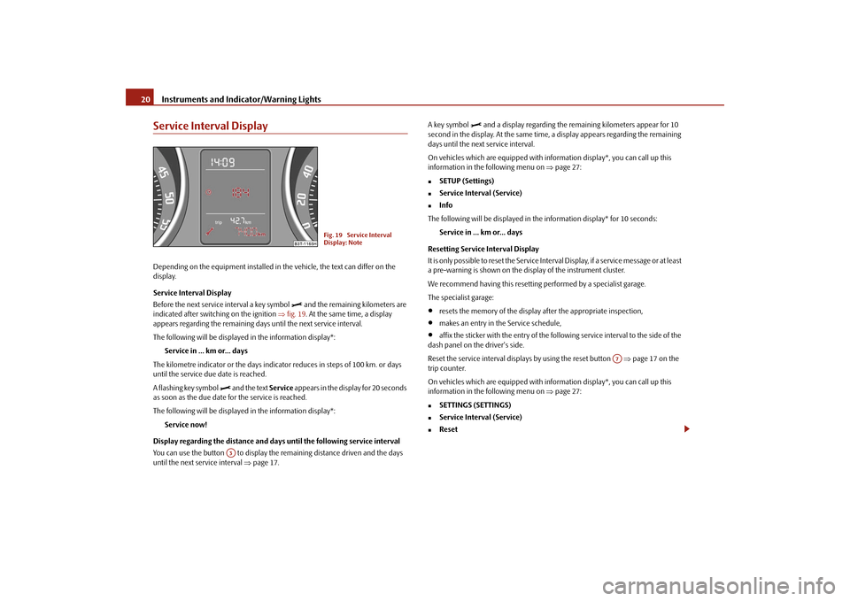
Service Interval DisplayDepending on the equipment installed in the vehicle, the text can differ on the display. Service Interval Display Before the next service interval a key symbol
and the remaining kilometers are
indicated after switching on the ignition
⇒fig. 19
. At the same time, a display
appears regarding the remaining days until the next service interval. The following will be displayed in the information display*:
Service in ... km or... days
The kilometre indicator or the days indica
tor reduces in steps of 100 km. or days
until the service due date is reached. A flashing key symbol
and the text
Service
appears in the display for 20 seconds
as soon as the due date for the service is reached. The following will be displayed in the information display*:
Service now!
Display regarding the distance and days
until the following service interval
You can use the button to display the re
maining distance driven and the days
until the next service interval
⇒page 17.
A key symbol
and a display regarding the remaining kilometers appear for 10
second in the display. At the same time, a display appears regarding the remaining days until the next service interval. On vehicles which are equipped with in
formation display*, you can call up this
information in the following menu on
⇒page 27:
�„
SETUP (Settings)
�„
Service Interval (Service)
�„
Info
The following will be displayed in the information display* for 10 seconds:
Service in ... km or... days
Resetting Service Interval Display It is only possible to reset the Service Interval Display, if a service message or at least a pre-warning is shown on the display of the instrument cluster. We recommend having this resetting performed by a specialist garage.The specialist garage:•
resets the memory of the display after the appropriate inspection,
•
makes an entry in the Service schedule,
•
affix the sticker with the entry of the following service interval to the side of the
dash panel on the driver's side. Reset the service interval displays by using the reset button
⇒page 17 on the
trip counter. On vehicles which are equipped with in
formation display*, you can call up this
information in the following menu on
⇒page 27:
�„
SETTINGS (SETTINGS)
�„
Service Interval (Service)
�„
Reset
Fig. 19 Service Interval Display: Note
A3
A7
s2dk.1.book Page 20 Wednesday, April 8, 2009 12:23 PM
Page 37 of 294
Instruments and Indicator/Warning Lights
36
Have the vehicle inspected without delay by your specialist garage.
WARNING
•
If you do not pay attention to the warning light coming on and the corre-
sponding descriptions and warning notes, this may result in injuries or major vehicle damage.•
Always adjust your speed to suit weather, road, region and traffic condi-
tions. The route indicated by the warning light must not tempt you to disre-gard the national regulations for road traffic.
Caution
As long as the warning light
lights up, one must take into account an increased
fuel consumption and in certain circumst
ances a power reduction of the engine.
Note
Further information about
diesel particle filter
⇒page 200.
Airbag system
Monitoring the airbag system The warning light
comes on for a few seconds when the ignition is switched on.
There is a fault in the system if the warn
ing light does not go out or flashes while
driving
⇒
. This also applies if the warning light does not come on when the igni-
tion is switched on. The following text will be displayed in the information display*:
Airbag fault!
The functionality of the airbag system is also monitored electronically, when one airbag has been switched off Front, side and head airbags or belt tensioner which have been switched off using the vehicle
system tester:
•
The warning light
lights up for 4 seconds after switching on the ignition and
then flashes again for 12 seconds afterwards in 2 second intervals. The following text will be displayed in the information display*:
Airbag/belt tensio
ner deactivated!
Front passenger airbags switched off
using the switch for front passenger
airbags* in storage compartment on the front passenger side:•
the warning light
comes on for 4 seconds after the ignition has been
switched on,•
switching off airbags is indicated in the middle of the dash panel by the lighting
up of the warning light
(airbag switched off)
⇒page 183.
WARNING
Have the airbag system ch
ecked immediately by a specialist garage if a fault
exists. Otherwise, there is a risk of th
e airbag not being activated in the event
of an accident.Control system for exhaust
The warning light
comes on after the ignition has been switched on.
If the warning light does not go out after starting the engine or it lights up when driving, a fault exists in an exhaust relevant component. The engine management system selects an emergency programme which enables you to drive to the nearest specialist garage by adopting a gentle style of driving.Electromechanical power steering
The warning light
comes on for a few seconds when the ignition is switched on.
If the warning light after switching on the ig
nition or when driving lights up contin-
uously, a fault exists in the el
ectromechanical power steering.
•
If the
yellow
warning light lights up
, this indicates a partial failure of the
power steering and the steering forces can be greater.
s2dk.1.book Page 36 Wednesday, April 8, 2009 12:23 PM
Page 62 of 294

Lights and Visibility
61
Using the system
Safety
Driving Tips
General Maintenance
Breakdown assistance
Technical Data
− It also concerns reverse light and turn signal lights. − This mist has no influence on th
e life of the lighting system.
Daylight driving lights*In some countries, the national legisl
ation requires that the vehicles are
equipped with the function
daylight driving lights.
Switching on daylight driving lights – Switch on the ignition without turnin
g the light switch out of the posi-
tion 0.
Deactivate function daylight driving lights – Pull the turn signal light lever towards the steering wheel up to 3
seconds after switching on the ignition
and at the same time, slide it to
the bottom and hold it in this position for at least 3 seconds.
Activate function daylight driving lights – Pull the turn signal light lever towards the steering wheel up to 3
seconds after switching on the ignition
and at the same time, slide it to
the top and hold it in this position for at least 3 seconds.
When the daylight driving lights are swit
ched on, also the low beam with reduced
brightness shines together with the side
lights (approx. 92 % of the performance).
This contributes to a longer life of the lamps for the low beam. When the daylight driving lights are switched on, the illumination of the instrument cluster is switched off, however, it is switched on in the position
when it is dark
and the low beam shines with full brightness (100 % of the performance). On vehicles fitted with an information displa
y*, you can activate or
deactivate in the
menu the function daylight driving lights:�„
SETUP (Settings)
�„
Lights & Vision (Lights & Vision)
Automatic light control*Switching on automatic light control* – Turn the light switch
⇒
fig. 56
into position
.
Switching off automatic light control* – Turn the light switch to the position 0,
or
.
If the light switch is in the position
, the symbol illuminates when the ignition
is switched on
next to the light switch. If th
e low beam is activated with the
light sensor, the symbol
illuminates additionally next to the light switch.
If the light comes on automatically, the side lights and low beam as well as licence plate light light up at the same time. If the automatic light control is switched
on, the light is regulated with the light
sensor in the rear mirror holder. If the light intensity drops below the set value, e.g when driving during the day into a tunnel, the low beam and the side lights as well as the licence plate light come on automa
tically. If the light intensity increases
again, the lights switch off automatically. Motorway lights If the automatic light control has been switched on and the vehicle speed is over 140 km/h for at least 10 seconds, the side
lights and low beam are switched on
automatically.
Fig. 56 Dash panel: Light switch
s2dk.1.book Page 61 Wednesday, April 8, 2009 12:23 PM
Page 65 of 294
Lights and Visibility
64
Mode city In the mode “city”, the dispersion of the cone
of light in front of the vehicle is wider
and the width of illumination is shorter. It
has as an aim to il
luminate the adjacent
footpaths, crossings, pedestrian crossings etc. The mode is active at speeds of 15 - 50 km/h. Mode motorway In the mode “motorway” the disp
ersion of the cone of light is so widespread, that it
illuminates also the left (and right)
7) lane of the motorway, so that the driver can
react in time to an obstacle or any other
danger. The mode is activated stepwise as
of a speed of 90 km/h. It gains its greate
st effectiveness at speeds above 120 km/h.
Tourist light This mode makes it possible to drive in
countries with opposi
ng traffic system,
driving on the left/right, without dazzling the oncoming vehicles. When the mode “tourist light” is active, the above mentioned modes and the side to side swivel of the headlight is deactivated. The mode “tourist light” is activated / deac
tivated via the informat
ion display* in the
menu:�„
SETUP (Settings)
�„
Tra v e l m o d e�„
Off
�„
On
Cornering lights The cornering lights are used to illuminate the curves by means of the cone of light swiveling together with the front headlight with Xenon lights*. This function is active when the speed of the car increases to more than 10km/h. The swiveling function of the headlights ca
n be switched off / on via the menu point
Assistant
in the main menu of the Information display*
⇒page 27.
Note
•
The AHL system* complements the functions of the fog lights with the function
“Corner”
⇒page 64 and the function of the
dynamic headlight beam range*.
•
The System AHL* is solely delivered with Bi-Xenon gas discharge bulbs for low
beam and main beam lights.Fog lights
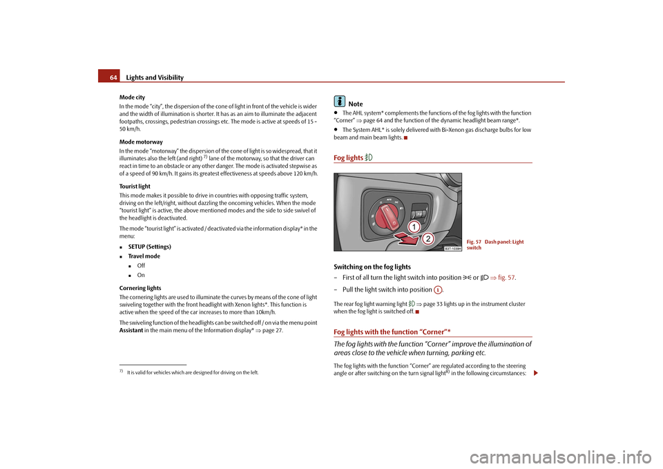
Switching on the fog lights – First of all turn the light switch into position
or
⇒
fig. 57
.
– Pull the light switch into position .The rear fog light warning light
⇒page 33 lights up in the instrument cluster
when the fog light is switched off.Fog lights with the function “Corner”* The fog lights with the function “C
orner” improve the illumination of
areas close to the vehicle when turning, parking etc.The fog lights with the function “Corner” are regulated according to the steering angle or after switching on the turn signal light
8) in the following circumstances:
7)It is valid for vehicles which are designed for driving on the left.
Fig. 57 Dash panel: Light switch
A1
s2dk.1.book Page 64 Wednesday, April 8, 2009 12:23 PM
Page 66 of 294
Lights and Visibility
65
Using the system
Safety
Driving Tips
General Maintenance
Breakdown assistance
Technical Data
•
the vehicle is stationary an
d the engine is running or
it moves with a speed of
maximum 40 km/h,•
the daylight driving lights are not switched on,
•
the low beam is switched on or th
e light switch is in the position
and the
intensity of the ambient light causes
the low beam to be switched on,
•
the fog lights are not switched on,
•
no reverse gear is engaged.Note
If you engage the reverse gear during the
active function “Corner”, both fog lights
illuminate.Rear fog light
Switching on the rear fog light – First of all turn the light switch into position
or
⇒
page 64,
fig. 57
.
– Pull the switch into position .The rear fog light warning light
⇒page 33 lights up in the instrument cluster
when the fog light is switched off. Only the rear fog light of the trailer lights up automatically when you are towing a trailer
using a factory-fitted towing device
which is fitted with the rear fog light.
The rear fog light is located in the rear light array on the driver's side.
Caution
The rear fog light should only be switched
on if visibility is
particularly poor
(conform with any varying legal provisions)
to avoid dazzling vehicles behind your
vehicle.
Instrument lighting
You can adjust the brightness
of the instrument lighting.
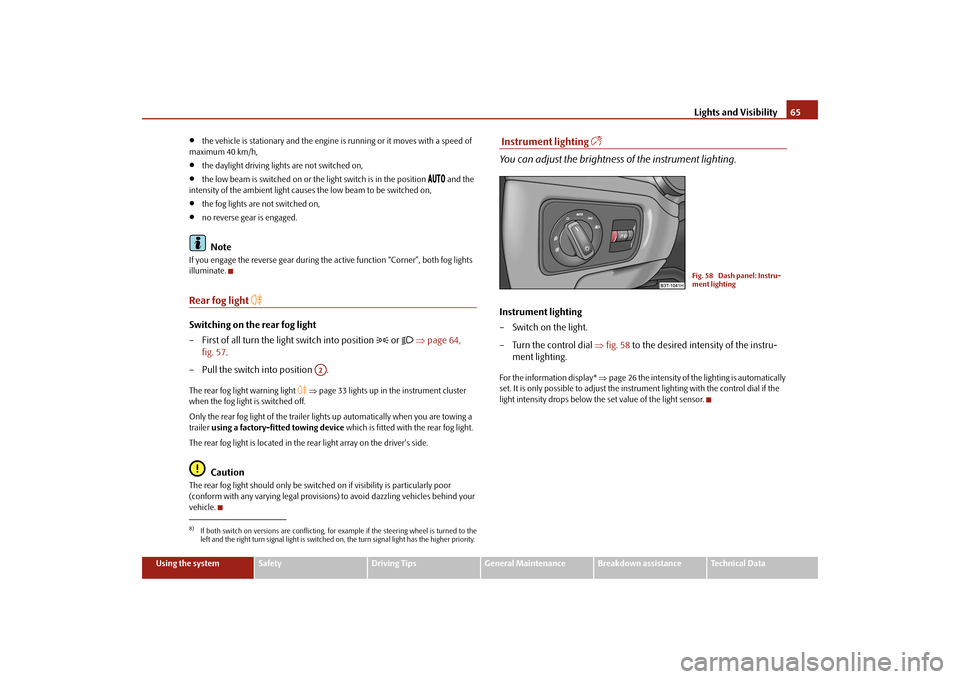
Instrument lighting – Switch on the light. – Turn the control dial
⇒
fig. 58
to the desired intensity of the instru-
ment lighting.
For the information display*
⇒page 26 the intensity of the lighting is automatically
set. It is only possible to adjust the inst
rument lighting with the control dial if the
light intensity drops below the set value of the light sensor.
8)If both switch on versions are conflicting, fo
r example if the steering wheel is turned to the
left and the right turn signal light is switched on, the turn signal light has the higher priority.
A2
Fig. 58 Dash panel: Instru-ment lighting
s2dk.1.book Page 65 Wednesday, April 8, 2009 12:23 PM
Page 79 of 294
Seats and Stowage
78
Seats and StowageFront seatsBasic informationThe front seats have a wide range of different settings and can thus be matched to the physical characteristics of the driver and front passenger. Correct adjustment of the seats is particularly important for:•
safely and quickly reaching the controls,
•
a relaxed, fatigue-free body position,
•
achieving the maximum protection offere
d by the seat belts and the airbag
system.
WARNING
•
Never transport more occupants than the maximum seating in the
vehicle.•
Each occupant must correctly fasten
the seat belt belonging to the seat.
Children must be fastened
⇒page 185, “Transporting children safely” with
a suitable restraint system.•
The front seats and the head restraints must always be adjusted to match
the body size of the seat occupant as well as the seat belts must always be correctly fastened in order to provide an optimal protection for you and your occupants.•
Always keep your feet in the footwell
when the car is being driven - never
place your feet on the instrument panel, out of the window or on the surfaces of the seats. This is particularly important for the front seat passenger. You will be exposed to increased risk of injury if it becomes necessary to apply the brake or in the event of an accident. If an airbag is deployed, you may suffer fatal injuries
when adopting an incorrect seated
position!•
It is important for the driver and front passenger to maintain a distance
of at least 25 cm from the steering wheel
or dash panel. Not maintaining this
minimum distance will mean that the airbag system will not be able to prop- erly protect you - hazard! The front
seats and the head restraints must
always also be correctly adjusted to match the body size of the occupant.•
Ensure that there are no objects in
the footwell as any objects may get
behind the pedals during a driving or
braking manoeuvre. You would then
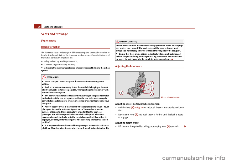
no longer be able to operate the clutch, to brake or accelerate.Adjusting the front seatsAdjusting a seat in a forward/back direction – Pull the lever
⇒
fig. 77
up and push the seat into the desired posi-
tion.
– Release the lever and push the seat further until the lock is heard
to engage.
Adjusting height of seat – Lift the seat if required by pulling or pumping lever upwards.
WARNING (continued)
Fig. 77 Controls at seat
A1
A1
A2
s2dk.1.book Page 78 Wednesday, April 8, 2009 12:23 PM
Page 167 of 294
Passive Safety
166
Manual front passenger adjustment
⇒page 78, “Adjusting the front seats”.
Electrical front passenger seat adjustment
⇒page 79, “Adjusting front seats electri-
cally*”.
WARNING
•
The front seats and the head restraints must always be adjusted to match
the body size of the seat occupant as well as the seat belts must always be correctly fastened in order to provide an optimal protection for you and your occupants.•
The front passenger must maintain a distance of at least 25 cm to the
dash panel. Not maintaining this minimum distance will mean that the airbag system will not be able
to properly protect you - hazard!
•
Always keep your feet in the footwell
when the car is being driven - never
place your feet on the instrument panel, out of the window or on the surfaces of the seats. You will be exposed to increased risk of injury if it becomes necessary to apply the brake or in the event of an accident. If an airbag is deployed, you may suffer fata
l injuries when adopting an incorrect
seated position!•
The backrests must not be angled too far back when driving otherwise
this will affect proper operation of th
e seat belts and of the airbag system -
risk of injury!Correct seated position for the occupants on the rear seats Occupants on the rear seats must sit upright, keep the feet in the footwell and must have their se
at belts correctly fastened.
To reduce the risk of injury in the event of a sudden braking manoeuvre or an acci- dent, the occupants on the rear seats must observe the following.•
Adjust the head restraints so that the top edge of the head restraints are at the
same level as the upper part of your head
⇒page 165, fig. 161
.
•
Fasten the seat belt correctly
⇒page 170, “How are seat belts correctly
fastened?”.
•
If you are transporting
⇒page 185, “Transporting children safely” children in
the vehicle, please use a suitable child restraint system.
WARNING
•
The head restraints must always be adjusted to match the body size, in
order to offer an optimal protection for you and your occupants.•
Always keep your feet in the footwell
when the car is being driven - never
put your feet out of the window or on the surfaces of the seats. You will be exposed to increased risk of injury if it becomes necessary to apply the brake or in the event of an accident. If an airbag is deployed, you may suffer fatal injuries when adopting an incorrect seated position!•
If the occupants on the rear seats are not sitting upright, the risk of injury
is increased due to incorrec
t routing of the seat belt.
Examples of an incorrect seated position An incorrect seated position can lead to severe injuries or death for the occupants.Seat belts offer their optimum protection on
ly if the webbing of the seat belts is
properly routed. Incorrect seated positio
ns considerably reduce the protective
functions of the seat belts and therefore incr
ease the risk of injury due to an incor-
rect routing of the seat belt. The driver is fully responsible for himself and the occu-pants, in particular for the children. Do
not permit an occupant to adopt an incor-
rect seated position when the car is moving. The following list contains
the examples of seated positions which are dangerous
for the occupants. This list is not comple
te, however we would like you to get inter-
ested in this subject. Therefore, while the car is moving never:•
stand up in the vehicle,
•
stand up on the seats,
•
kneel onto the seats,
•
tilt the backrest fully to the back,
s2dk.1.book Page 166 Wednesday, April 8, 2009 12:23 PM
Page 175 of 294

Airbag system
174
Airbag systemDescription of the airbag systemGeneral information on the airbag systemThe front airbag system is complementary to the three-point seat belts and offers additional protection for the head and ches
t area of the driver and passenger in the
event of a frontal collision. In the case of a violent side crash, the si
de* and head* airbags reduce the risk of
injuries to the occupants on
the part of the body facing
the side of the accident
⇒
.
The airbag system is only functional after the ignition has been switched on.The operational readiness of the airbag system is monitored electronically. The airbag warning light comes on for a few seconds each time the ignition is switched on. The airbag system (according to vehicl
e equipment) essent
ially consists of:
•
an electronic control unit,
•
front airbag for the driver and front passenger,
•
Driver's knee airbag*,
•
front side airbags,
•
Rear side airbags*,
•
head airbags*,
•
an airbag warning light in the instrument cluster,
•
a front passenger airbag switch*,
•
an indicator light for a switched off fron
t seat passenger airbag* in the middle
of the dash panel. A fault in the airbag system exists if:•
the airbag indicator light does not light
up when the ignition is switched on,
•
the warning light does not go out after about 4 seconds after the ignition is
switched on,
•
the airbag indicator light goes out and comes on again after the ignition is
switched on,•
the airbag indicator light comes on or flickers when driving,
•
an airbag indicator light showing a swit
ched-off front passenger airbag* in the
middle of the dash panel flashes.
WARNING
•
To enable the occupants of a car to be protected with the greatest
possible effect when the airbag is deployed, the front seats must be ⇒ page 164, “Correct seated position” co
rrectly adjusted to match the body
size of the occupant.•
If you do not fasten the seat belts when driving, lean too far forward or
adopt an incorrect seated position, you are exposing yourself to increased risk of injury in the event of an accident.•
Have the airbag system checked imme
diately by a specialist garage if a
fault exists. Otherwise, there is a risk of the airbag not being activated in the event of an accident. •
No modifications of any kind may be made to parts of the airbag system.
•
It is prohibited to manipulate individual parts of the airbag system as this
might result in the airbag being deployed.•
The protective function of the airbag system is sufficient for only one
accident. The airbag system must then
be replaced if the airbag has been
deployed.•
The airbag system needs no maintenance during its working life.
•
If you sell your car, please hand over the complete vehicle documenta-
tion to the new owener. Please note that the documents relating to the possibility of deactivating the front passenger airbag are also part of the vehicle documents!•
If the vehicle or individual parts of
the airbag system are scrapped, it is
essential to observe the relevant safety precautions. The authorised Škoda Service Partners are famili
ar with these regulations.
s2dk.1.book Page 174 Wednesday, April 8, 2009 12:23 PM
Page 261 of 294
Fuses and light bulbs
260
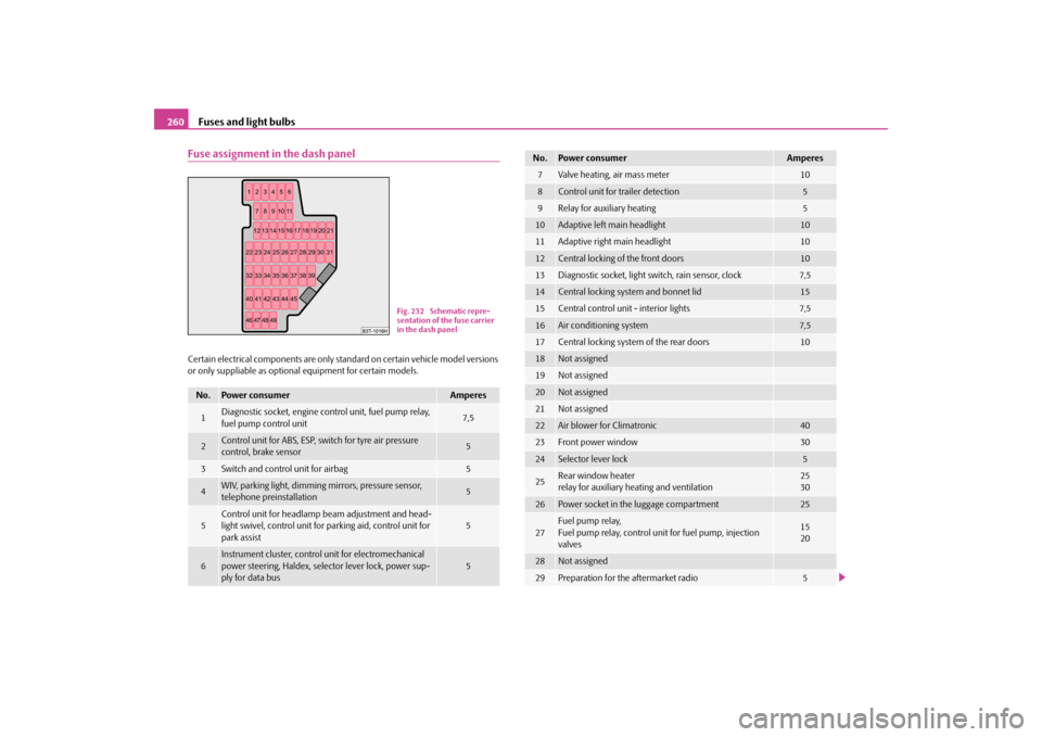
Fuse assignment in the dash panelCertain electrical components are only st
andard on certain vehicle model versions
or only suppliable as optional
equipment for certain models.
No.
Power consumer
Amperes
1
Diagnostic socket, engine control unit, fuel pump relay, fuel pump control unit
7,5
2
Control unit for ABS, ESP, switch for tyre air pressure control, brake sensor
5
3
Switch and control unit for airbag
5
4
WIV, parking light, dimming mirrors, pressure sensor, telephone preinstallation
5
5
Control unit for headlamp beam adjustment and head- light swivel, control unit for parking aid, control unit for park assist
5
6
Instrument cluster, control
unit for electromechanical
power steering, Haldex, selector lever lock, power sup- ply for data bus
5
Fig. 232 Schematic repre- sentation of the fuse carrier in the dash panel
7
Valve heating, air mass meter
10
8
Control unit for trailer detection
5
9
Relay for auxiliary heating
5
10
Adaptive left main headlight
10
11
Adaptive right main headlight
10
12
Central locking of the front doors
10
13
Diagnostic socket, light switch, rain sensor, clock
7,5
14
Central locking system and bonnet lid
15
15
Central control unit - interior lights
7,5
16
Air conditioning system
7,5
17
Central locking system of the rear doors
10
18
Not assigned
19
Not assigned
20
Not assigned
21
Not assigned
22
Air blower for Climatronic
40
23
Front power window
30
24
Selector lever lock
5
25
Rear wind
ow heater
relay for auxiliary heating and ventilation
2530
26
Power socket in the luggage compartment
25
27
Fuel pump relay, Fuel pump relay, control unit for fuel pump, injection valves
1520
28
Not assigned
29
Preparation for the aftermarket radio
5
No.
Power consumer
Amperes
s2dk.1.book Page 260 Wednesday, April 8, 2009 12:23 PM