service indicator SKODA SUPERB 2009 2.G / (B6/3T) Owner's Manual
[x] Cancel search | Manufacturer: SKODA, Model Year: 2009, Model line: SUPERB, Model: SKODA SUPERB 2009 2.G / (B6/3T)Pages: 294, PDF Size: 21.33 MB
Page 4 of 294
Contents3
Using the system
Safety
Driving Tips
General Maintenance
Breakdown assistance
Technical Data
ContentsLayout of this Owner's Manual
(explanations)
. . . . . . . . . . . . . . . . . . . . . . . . . .
Using the system
. . . . . . . . . . . . . . . . . . . . . .
Cockpit
. . . . . . . . . . . . . . . . . . . . . . . . . . . . . . . . . . . . . . . .
Overview . . . . . . . . . . . . . . . . . . . . . . . . . . . . . . . . . . . .
The brief instruction
. . . . . . . . . . . . . . . . . . . . . . . . . .
Basic functions and important information . . . . .
Instruments and Indicator/Warning Lights
. . .
General view of the instrument cluster . . . . . . . . .
Engine revolutions counter . . . . . . . . . . . . . . . . . . . .
Speedometer . . . . . . . . . . . . . . . . . . . . . . . . . . . . . . . .
Coolant temperature gauge . . . . . . . . . . . . . . . . . . .
Fuel gauge . . . . . . . . . . . . . . . . . . . . . . . . . . . . . . . . . . .
Counter for distance driven . . . . . . . . . . . . . . . . . . .
Service Interval Display . . . . . . . . . . . . . . . . . . . . . . .
Digital clock . . . . . . . . . . . . . . . . . . . . . . . . . . . . . . . . . .
Multi-functional indicator (onboard computer)*
Information display* . . . . . . . . . . . . . . . . . . . . . . . . . .
Auto Check Control* . . . . . . . . . . . . . . . . . . . . . . . . . .
Warning lights . . . . . . . . . . . . . . . . . . . . . . . . . . . . . . . .
Unlocking and locking
. . . . . . . . . . . . . . . . . . . . . . . .
Key . . . . . . . . . . . . . . . . . . . . . . . . . . . . . . . . . . . . . . . . . .
Changing the battery of the radio remote control
Electronic immobiliser . . . . . . . . . . . . . . . . . . . . . . . .
Child safety lock . . . . . . . . . . . . . . . . . . . . . . . . . . . . . .
Central locking system . . . . . . . . . . . . . . . . . . . . . . . .
Remote control . . . . . . . . . . . . . . . . . . . . . . . . . . . . . . .
Description . . . . . . . . . . . . . . . . . . . . . . . . . . . . . . . . . .
Unlocking and locking car . . . . . . . . . . . . . . . . . . . . .
Synchonisation of the remote control . . . . . . . . . . Anti-theft alarm system* . . . . . . . . . . . . . . . . . . . . . .
Power windows . . . . . . . . . . . . . . . . . . . . . . . . . . . . . .
Electric sliding/tilting roof* . . . . . . . . . . . . . . . . . . . .
Lights and Visibility
. . . . . . . . . . . . . . . . . . . . . . . . . . .
Lights . . . . . . . . . . . . . . . . . . . . . . . . . . . . . . . . . . . . . . . .
Interior lighting . . . . . . . . . . . . . . . . . . . . . . . . . . . . . . .
Visibility . . . . . . . . . . . . . . . . . . . . . . . . . . . . . . . . . . . . .
Windshield wiper and wash system . . . . . . . . . . . .
Rear-view mirror . . . . . . . . . . . . . . . . . . . . . . . . . . . . .
Exterior mirror . . . . . . . . . . . . . . . . . . . . . . . . . . . . . . .
Automatic dimming exterior mirror* . . . . . . . . . . .
Seats and Stowage
. . . . . . . . . . . . . . . . . . . . . . . . . . . .
Front seats . . . . . . . . . . . . . . . . . . . . . . . . . . . . . . . . . . .
Adjusting front seats electrically* . . . . . . . . . . . . . .
Head restraints . . . . . . . . . . . . . . . . . . . . . . . . . . . . . . .
Middle rear head restraint . . . . . . . . . . . . . . . . . . . . .
Rear seats . . . . . . . . . . . . . . . . . . . . . . . . . . . . . . . . . . . .
luggage compartment . . . . . . . . . . . . . . . . . . . . . . . .
The roof rack* . . . . . . . . . . . . . . . . . . . . . . . . . . . . . . . .
Cup holder . . . . . . . . . . . . . . . . . . . . . . . . . . . . . . . . . . .
Ashtray . . . . . . . . . . . . . . . . . . . . . . . . . . . . . . . . . . . . . .
Cigarette lighter*, power sockets . . . . . . . . . . . . . . .
Storage compartments . . . . . . . . . . . . . . . . . . . . . . . .
Air conditioning system
. . . . . . . . . . . . . . . . . . . . . .
Introduction . . . . . . . . . . . . . . . . . . . . . . . . . . . . . . . . .
Air outlet vents . . . . . . . . . . . . . . . . . . . . . . . . . . . . . . .
Climatic (semi-automatic air conditioning system)
Climatronic* (automatic air conditioning) . . . . . .
Auxiliary heating (auxiliary heating and
ventilation)* . . . . . . . . . . . . . . . . . . . . . . . . . . . . . . . . .
Starting-off and Driving
. . . . . . . . . . . . . . . . . . . . . . .
Setting steering wheel position . . . . . . . . . . . . . . . .
Ignition lock . . . . . . . . . . . . . . . . . . . . . . . . . . . . . . . . . . Starting the engine . . . . . . . . . . . . . . . . . . . . . . . . . . .
Rear parking aid* . . . . . . . . . . . . . . . . . . . . . . . . . . . . .
Front and rear parking aid* . . . . . . . . . . . . . . . . . . . .
Park Assist* . . . . . . . . . . . . . . . . . . . . . . . . . . . . . . . . . .
Cruise control system (CCS)* . . . . . . . . . . . . . . . . . .
Automatic gearbox DSG*
. . . . . . . . . . . . . . . . . . . . .
Automatic gearbox DSG* . . . . . . . . . . . . . . . . . . . . .
Communication
. . . . . . . . . . . . . . . . . . . . . . . . . . . . . .
Multifunction steering wheel* . . . . . . . . . . . . . . . . .
Mobile phones and two-way radio systems . . . . .
Universal telephone preinstallation GSM II* . . . .
Phone voice phonebook* . . . . . . . . . . . . . . . . . . . . .
Universal telephone preinstallation GSM III* . . . .
Phone voice phonebook* . . . . . . . . . . . . . . . . . . . . .
Inputs AUX-IN* and MDI* . . . . . . . . . . . . . . . . . . . . .
CD changer* . . . . . . . . . . . . . . . . . . . . . . . . . . . . . . . . .
Safety
. . . . . . . . . . . . . . . . . . . . . . . . . . . . . . . . . . . . . .
Passive Safety
. . . . . . . . . . . . . . . . . . . . . . . . . . . . . . . . .
Basic information . . . . . . . . . . . . . . . . . . . . . . . . . . . .
Correct seated position . . . . . . . . . . . . . . . . . . . . . . .
Seat belts
. . . . . . . . . . . . . . . . . . . . . . . . . . . . . . . . . . . . . .
Why seat belts? . . . . . . . . . . . . . . . . . . . . . . . . . . . . . .
The physical principle of a frontal collision . . . . .
Important safety information regarding the use of
seat belts . . . . . . . . . . . . . . . . . . . . . . . . . . . . . . . . . . . .
How are seat belts correctly fastened? . . . . . . . . .
Airbag system
. . . . . . . . . . . . . . . . . . . . . . . . . . . . . . . . .
Description of the airbag system . . . . . . . . . . . . . . .
Front airbag . . . . . . . . . . . . . . . . . . . . . . . . . . . . . . . . . .
Driver's knee airbag* . . . . . . . . . . . . . . . . . . . . . . . . . 6
7
9
9
11
11
17
17
18
18
18
18
19
20
21
21
26
29
33
43
43
43
44
44
45
50
50
51
5252
54
57
60
60
68
70
73
75
76
77
78
78
79
82
83
84
86
91
92
93
94
95
104
104
105
106
109
112
117
117
118119
122
123
124
128
131
131
138
138
141
141
148
151
158
160
160
163
163
163
164
168
168
169
169
170
174
174
176
178
s2dk.1.book Page 3 Wednesday, April 8, 2009 12:23 PM
Page 18 of 294
Instruments and Indicator/Warning Lights
17
Using the system
Safety
Driving Tips
General Maintenance
Breakdown assistance
Technical Data
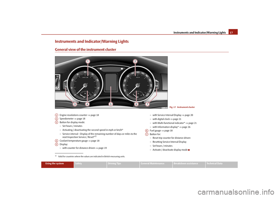
Instruments and Indicator/Warning LightsGeneral view of the instrument cluster
Engine revolutions counter
⇒page 18
Speedometer
⇒page 18
Button for display mode: − Set hours / minutes − Activating / deactivating the
second speed in mph or km/h*
− Service interval - Display of the remaining number of days or miles to the next Inspection Service / Reset*
1)
Coolant temperature gauge
⇒page 18
Display:− with counter for distance driven
⇒page 19
− with Service Interval Display
⇒page 20
− with digital clock
⇒page 21
− with Multi-functional indicator*
⇒page 21
− with Information display*
⇒page 26
Fuel gauge
⇒page 18
Button for: − Reset trip counter for distance driven − Resetting Service Interval Display − Set hours / minutes − Activate / deactivate display mode
Fig. 17 Instrument cluster
1)Valid for countries where the values are indicated in British measuring units.A1A2A3A4A5
A6A7
s2dk.1.book Page 17 Wednesday, April 8, 2009 12:23 PM
Page 21 of 294
Instruments and Indicator/Warning Lights
20
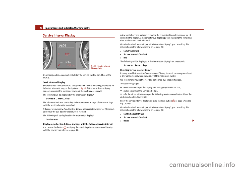
Service Interval DisplayDepending on the equipment installed in the vehicle, the text can differ on the display. Service Interval Display Before the next service interval a key symbol
and the remaining kilometers are
indicated after switching on the ignition
⇒fig. 19
. At the same time, a display
appears regarding the remaining days until the next service interval. The following will be displayed in the information display*:
Service in ... km or... days
The kilometre indicator or the days indica
tor reduces in steps of 100 km. or days
until the service due date is reached. A flashing key symbol
and the text
Service
appears in the display for 20 seconds
as soon as the due date for the service is reached. The following will be displayed in the information display*:
Service now!
Display regarding the distance and days
until the following service interval
You can use the button to display the re
maining distance driven and the days
until the next service interval
⇒page 17.
A key symbol
and a display regarding the remaining kilometers appear for 10
second in the display. At the same time, a display appears regarding the remaining days until the next service interval. On vehicles which are equipped with in
formation display*, you can call up this
information in the following menu on
⇒page 27:
�„
SETUP (Settings)
�„
Service Interval (Service)
�„
Info
The following will be displayed in the information display* for 10 seconds:
Service in ... km or... days
Resetting Service Interval Display It is only possible to reset the Service Interval Display, if a service message or at least a pre-warning is shown on the display of the instrument cluster. We recommend having this resetting performed by a specialist garage.The specialist garage:•
resets the memory of the display after the appropriate inspection,
•
makes an entry in the Service schedule,
•
affix the sticker with the entry of the following service interval to the side of the
dash panel on the driver's side. Reset the service interval displays by using the reset button
⇒page 17 on the
trip counter. On vehicles which are equipped with in
formation display*, you can call up this
information in the following menu on
⇒page 27:
�„
SETTINGS (SETTINGS)
�„
Service Interval (Service)
�„
Reset
Fig. 19 Service Interval Display: Note
A3
A7
s2dk.1.book Page 20 Wednesday, April 8, 2009 12:23 PM
Page 22 of 294
Instruments and Indicator/Warning Lights
21
Using the system
Safety
Driving Tips
General Maintenance
Breakdown assistance
Technical Data
Caution
We recommend that you do not reset the
Service Interval Disp
lay yourself other-
wise this can result in the service interval display being incorrectly set, which may also result in problems with operation of your vehicle.
Note
•
Never reset the display between service intervals otherwise this may result in
incorrect readouts.•
information is retained in the Service Interval Display also after the battery of
the vehicle is disconnected.•
If the instrument cluster is exchanged af
ter a repair, the correct values must be
entered in the counter for the Service Interval Display. This work is carried out by a specialist garage.•
The data displayed is the same after resetting the display with flexible service
intervals (QG1) using the reset button as that for a vehicle with fixed service inter- vals (QG2). We therefore recommend having
the Service Interval Display reset only
by an authorised Škoda Service Partner who is familiar with the procedure for reset-ting the display with a vehicle system tester.•
Please refer to the brochure Service sc
hedule for extensive information about
the service intervals.Digital clockThe time is set with the buttons and
⇒page 17, fig. 17
.
Select the display which you wish to chan
ge with the button and carry out the
change with the button . On vehicles which are fitted out with the information display*, it is possible to set the time in the menu
Time
⇒page 30.
WARNING
The clock should not be adjusted while driving for safety reasons but only when the vehicle is stationary!Multi-functional indicator (onboard computer)*IntroductionThe multi-functional indicator appears in the display
⇒page 22, fig. 20
or in the
information display
⇒page 26 depending on the equipment fitted to your vehicle.
The multi-functional indicator offers
you a range of useful information.
On vehicles which are fitted out with inform
ation display*, it is possible to switch
off the display of some information.
Caution
Pull out the ignition key while having contact with the display (for example when cleaning) in order to
prevent any damage.
A3
A7
A3
A7
The outside temperature
⇒page 24
Driving time
⇒page 24
Current fuel consumption
⇒page 24
Average fuel consumption
⇒page 24
Range
⇒page 25
Distance driven
⇒page 25
Average speed
⇒page 25
Current speed*
⇒page 25
Warning against excessive speeds*
⇒page 25
s2dk.1.book Page 21 Wednesday, April 8, 2009 12:23 PM
Page 28 of 294
Instruments and Indicator/Warning Lights
27
Using the system
Safety
Driving Tips
General Maintenance
Breakdown assistance
Technical Data
Caution
Pull out the ignition key while having cont
act with the display (for example when
cleaning) in order to prevent any damage.Main menu
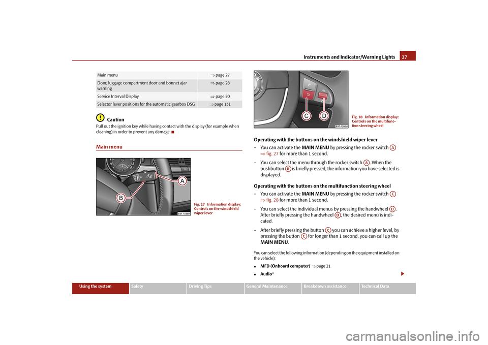
Operating with the buttons on the windshield wiper lever – You can activate the
MAIN MENU
by pressing the rocker switch
⇒
fig. 27
for more than 1 second.
– You can select the menu through the rocker switch . When the
pushbutton is briefly pressed, th
e information you have selected is
displayed.
Operating with the buttons on
the multifunction steering wheel
– You can activate the
MAIN MENU
by pressing the rocker switch
⇒
fig. 28
for more than 1 second.
– You can select the individual me
nus by pressing the handwheel .
After briefly pressing the handwh
eel , the desired menu is indi-
cated.
– After briefly pressing the button
you can achieve a higher level, by
pressing the button for longer than 1 second, you can call up the MAIN MENU
.
You can select the following information (d
epending on the equipment installed on
the vehicle):�„
MFD (Onboard computer)
⇒page 21
�„
Audio
*
Main menu
⇒page 27
Door, luggage compartment door and bonnet ajar warning
⇒ page 28
Service Interval Display
⇒page 20
Selector lever positions for the automatic gearbox DSG
⇒page 131
Fig. 27 Information display: Controls on the windshield wiper lever
Fig. 28 Information display: Controls on the multifunc-tion steering wheel
AA
AA
AB
ACAD
AD
AC
AC
s2dk.1.book Page 27 Wednesday, April 8, 2009 12:23 PM
Page 30 of 294
Instruments and Indicator/Warning Lights
29
Using the system
Safety
Driving Tips
General Maintenance
Breakdown assistance
Technical Data
Auto Check Control*Car stateThe Auto Check Control carries out a check of certain functions and vehicle compo- nents. The check is performed constantly
when the ignition is switched on, both
when the vehicle is stationary, as well as when driving. Some operational faults, urgent repairs, service work or other information appear in the display of the instrument cluster. The displays are shown with a red or yellow light symbol depending on the priority of the message. The red symbols indicate
danger
(priority 1) while the yellow symbols indicate a
warning
(priortity 2). Information for the driver
may also appear in addition to the
symbols
⇒page 33.
Shown in the menu
Vehicle status
, if there is at least one error message. After
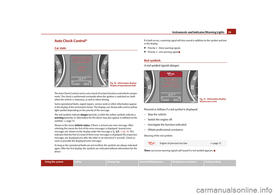
selecting this menu the first of the error messages is displayed. Several error messages are shown on the display under the message e.°g.
1/3
⇒fig. 30
. This
indicates that the first of a total of three error messages is displayed.The respective messages are displayed one after the other in an interval of 5 seconds. Check as soon as possible the displayed error messages. As long as the operational faults are not rectified, the symbols are always indicated again. After the first display, the symbols are indicated without information for the driver.
If a fault occurs, a warning signal will also sound in addition to the symbol and text in the display:•
Priority 1 - three warning signals
•
Priority 2 - one warning signal
Red symbols A red symbol signals danger.Proceed as follows if a red symbol is displayed: – Stop the vehicle. – Switch the engine off. – Investigate the function indicated.– Obtain professional assistance.Meaning of the red symbols: Three
successive warning signals will sound if a red symbol appears.
Fig. 30 Information display: Display of operational fault
Engine oil pressure too low
⇒ page 37
Fig. 31 Information display: Oil pressure is low
s2dk.1.book Page 29 Wednesday, April 8, 2009 12:23 PM
Page 31 of 294
Instruments and Indicator/Warning Lights
30
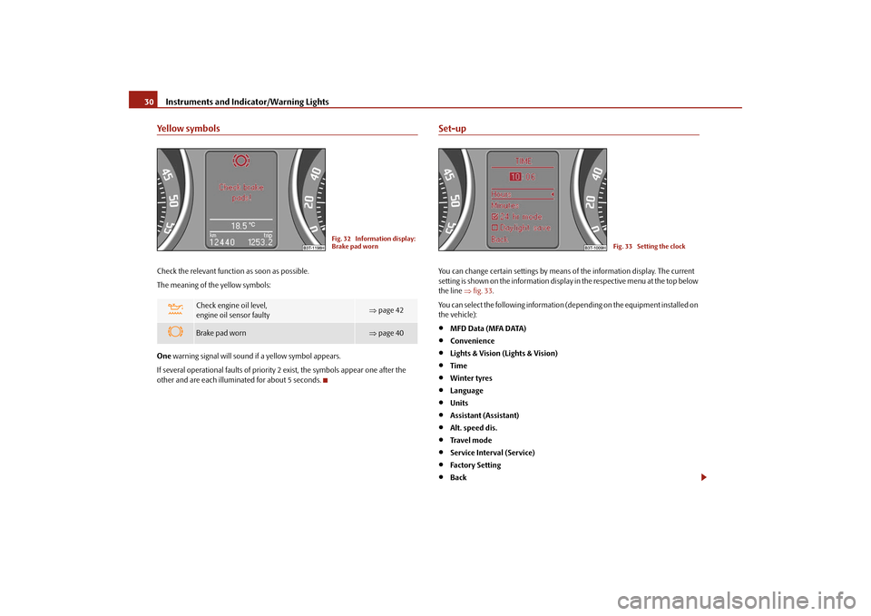
Yellow symbolsCheck the relevant function as soon as possible. The meaning of the yellow symbols: One
warning signal will sound if a yellow symbol appears.
If several operational faults of priority 2 exist, the symbols appear one after the other and are each illuminated for about 5 seconds.
Set-upYou can change certain settings by means of the information display. The current setting is shown on the information display
in the respective menu at the top below
the line
⇒fig. 33
.
You can select the following information (d
epending on the equipment installed on
the vehicle):•
MFD Data (MFA DATA)
•
Convenience
•
Lights & Vision (Lights & Vision)
•
Time
•
Winter tyres
•
Language
•
Units
•
Assistant (Assistant)
•
Alt. speed dis.
•
Tra v e l m o d e
•
Service Interval (Service)
•
Factory Setting
•
Back
Check engine oil level, engine oil sensor faulty
⇒ page 42
Brake pad worn
⇒page 40
Fig. 32 Information display: Brake pad worn
Fig. 33 Setting the clock
s2dk.1.book Page 30 Wednesday, April 8, 2009 12:23 PM
Page 33 of 294
Instruments and Indicator/Warning Lights
32
without dazzling the oncoming
vehicles. Furthe
r information
⇒page 64, “Tourist
light”. Service Here you can have the
kilometers still to be driven and the days until the following
service interval shown and the Service Interval Display reset. Factory Setting After selecting the menu point
Factory Setting
the factory setting of the informa-
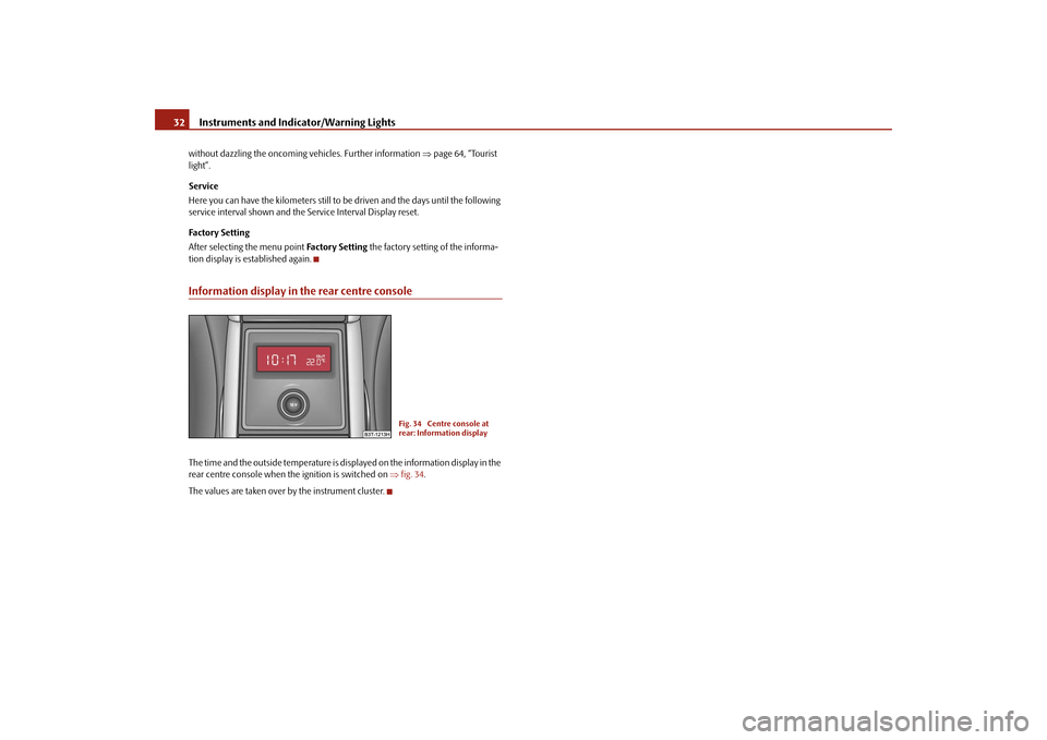
tion display is established again.Information display in the rear centre consoleThe time and the outside temperature is displayed on the information display in the rear centre console when the ignition is switched on
⇒fig. 34
.
The values are taken over by the instrument cluster.
Fig. 34 Centre console at rear: Information display
s2dk.1.book Page 32 Wednesday, April 8, 2009 12:23 PM
Page 40 of 294
Instruments and Indicator/Warning Lights
39
Using the system
Safety
Driving Tips
General Maintenance
Breakdown assistance
Technical Data
Note
If the battery has been disconnected
and reconnected, the warning light
comes
on after switching on the ignition. The warn
ing light must go out after driving a short
distance.Electronic stability programme (ESP)*
The warning light
comes on for a few seconds when the ignition is switched on.
Components of the ESP system also include the Traction Control System (TCS), Electronic Differential Lock (EDL), an
d the Antilock Brake System ABS (ABS).
The warning light comes on when drivin
g when a control cycle is activated.
The warning light will come on and remains on if the ESP is switched off or if there is a fault in the system. The fact that the ESP system operates together with the ABS means that the ESP warning light will also come on if the
ABS system is not operating properly.
If the warning light
comes on immediately after starting the engine, the ESP
system can be switched off for technical
reasons. In this case, the ESP system can
be switched on again by switching the ignition on and off. If the warning light goes out, the ESP system is fully functional again. Further information on the ESP
⇒page 193, “Electronic stability programme
(ESP)*”. Electronic Differential Lock (EDL)* The EDL is a part of the ESP. A fault in the EDL is indicated by the ESP warning light in the instrument cluster. Have the vehicle inspected without delay by an author- ised Škoda Service Partner. Further information on the EDL
⇒page 194, “Electronic
Differential Lock (EDL)*”.
Note
If the battery has been disconnected
and reconnected, the warning light
comes
on after switching on the ignition. The warn
ing light must go out after driving a short
distance.
Selector lever lock*
If the
green
warning light
lights up, operate the brake pedal. This is necessary, in
order to be able to move the selector lever out of the position
P or N.
Tyre inflation pressure*
The warning light
lights up, if there is a substantial drop in inflation pressure in
one of the tyres. Reduce the speed and check or correct as soon as possible the inflation pressure in the tyres
⇒page 235.
If the warning light flashes, there is a system fault. Visit the nearest specialist garage and have the fault rectified. Further information about tyre pressure-control system
⇒page 199.
WARNING
•
When the warning light
lights up, immediately reduce the speed and
avoid sudden steering and brake mano
euvres. Please stop the vehicle
without delay at the nearest possible stop and inspect the tyres and their inflation pressures.•
Under certain circumstances (e.g. sporty style of driving, wintry or
unpaved roads) the warning light
can be delayed or does not light up at
all.
Note
If the battery has been disconnected, the warning light
comes on after switching
on the ignition. The warning light must go out after driving a short distance.Antilock brake system (ABS)
The warning light
shows the functionality of the ABS.
s2dk.1.book Page 39 Wednesday, April 8, 2009 12:23 PM
Page 46 of 294
Unlocking and locking
45
Using the system
Safety
Driving Tips
General Maintenance
Breakdown assistance
Technical Data
Switching child safety lock on – Use the vehicle key to turn the slit in the rear door to the left in the
direction of the arrow
⇒
page 44, fig. 39
.
Switching child safety lock off – Use the vehicle key to turn the slit
to the right against the direction of
the arrow.
So long as the child safety lock is switched
on it is not possib
le to open the door
from the inside with the door opening lever. In this case the door can be opened only from the outside.Central locking systemDescriptionUnlocking or locking the vehicle causes
all the doors and the fuel filler flap to be
unlocked or locked at the same time by th
e central locking system. The boot lid is
unlocked when opening. Afterwards you ca
n open the boot lid by pressing the
handle on the lower edge of the boot lid
⇒page 48.
Operation of the central locking system is possible:•
by using the radio remote control
⇒page 51,
•
using the buttons for the central locking system
⇒page 46,
•
from the outside using the vehicle key
⇒page 47, “Emergency unlocking and
locking of the driver's door”. Indicator light in the driver's door After locking the vehicle the indicator light flashes for 2 seconds fast, then more slowly. If the vehicle is locked and the safe securing system
⇒page 46 is not operating, the
indicator light in the driver door flashes for about 2 seconds fast, goes out and starts to flash slowly after about 30 seconds.
If the indicator light first of all flashes fast
for about 2 seconds, afterwards lights up
for about 30 seconds without interruption an
d then flashes slowly, there is a fault in
the system of the central locking or in the
interior monitor and in the towing protec-
tion monitoring*
⇒page 53. Visit a specialist garage to obtain assistance.
Convenience operation of windows One can open and close the windows when opening and closing the vehicle ⇒ page 56. Opening a single door* This function allows one to just unlock
the driver's door. The other doors and the
fuel filler flap remain locked and are only unlocked after repetitive unlocking. You can have the function opening a single
door activated by an authorised Škoda
Service Partner on request or you can activate it yourself with the aid of the Infor- mation display*
⇒page 30.
Automatic locking* All the doors and the boot lid are locked automatically once the car reaches a speed of about 15 km/h. If the ignition key is withdrawn, the car
is then automatically unlocked again. In
addition, it is possible for the driver or front passenger to unlock the car by pressing the central locking button
⇒page 46 or by pulling the door opening lever on one
of the front doors. You can have the function of the automatic
locking activated by a specialist garage
on request or you can also activate it yourself with the aid of the Information display*
⇒page 30.
WARNING
Locking the doors prevents involuntary
opening in an exceptional situation
(an accident). Locked doors prevent unwanted entry into the vehicle from outside, for example at road crossings. Locked doors do, however, make it more difficult for rescuers to get into
the vehicle in an emergency - danger to
life!
s2dk.1.book Page 45 Wednesday, April 8, 2009 12:23 PM