width SKODA SUPERB 2009 2.G / (B6/3T) Owner's Manual
[x] Cancel search | Manufacturer: SKODA, Model Year: 2009, Model line: SUPERB, Model: SKODA SUPERB 2009 2.G / (B6/3T)Pages: 294, PDF Size: 21.33 MB
Page 64 of 294

Lights and Visibility
63
Using the system
Safety
Driving Tips
General Maintenance
Breakdown assistance
Technical Data
•
You can change the illumination period
for the Coming Home Function by
means of the information display*.Leaving Home FunctionThis function makes it possible to switch on the lights when approaching the vehicle. Switching on Leaving Home Function – Unlock the vehicle with the radio remote control - the lights come on.Depending on equipment fitted the function Leaving Home switches on the following lights:•
Parking lights,
•
Low beam,
•
Entry lighting in the exterior mirrors,
•
Licence plate light.
Leaving Home Function The function Leaving Home is controlled wi
th the light sensor in the mount of the
interior rear mirror. If the light intensity is higher than the set value of the light sensor, the Leaving Home Function is not
switched on after unlocking the vehicle
with the radio remote control. After unlocking the vehicle with the radio remote control, the lights come on for 30 seconds. The Leaving Home Function is also switched off after the ignition is switched on and after locking the vehicle. If no door is opened within
30 seconds, the lights go out and the vehicle is locked
automatically.
Note
•
If the Leaving Home Function is switch
ed on constantly, the battery will be
heavily discharged particular
ly in short-haul traffic.
•
The switching on of the described lights
should only be und
ertaken in accord-
ance with the legal requirements.•
You can change the illumination period
for the Leaving Home Function by
means of the information display*.Adaptive headlights (AHL)*Switch on Adaptive headlights (AHL)* – Turn the light switch
⇒
page 61, fig. 56
into position
.
The outer illumination switches on if:•
the light sensor recognizes the low light intensity,
•
no reverse gear is engaged,
•
the operation “tourist light” is not switched on.
The light sensor switches on the full ou
ter illumination at low light intensity.
System AHL* makes it possible to change
the length and width of illumination of
the headlight. The length and width of i
llumination changes automatically in rela-
tion to the vehicle speed and the use of the windscreen wiper. System AHL* operates in the following modes. Mode out of town The mode “out of town” is a basic mode. The dispersion of the cone of light in front of the vehicle is similar to the low beam. The mode is active if none of the following modes are active. Mode rain In the mode “rain” the dispersion of the cone of light in front of the vehicle is wider and the width of illumination is shorter,
so that during bad weather (rain) the
dazzling of the oncoming drivers can be reduced. The mode is activated at speeds of 15 - 70 km/h and if the windscreen wi
pers continuously operate for a period of
time longer than 2 minutes. The mode
is deactivated when dropping below or
exceeding the set speed limit or if the windscreen wipers have been switched off for a period of time longer than 8 minutes.
s2dk.1.book Page 63 Wednesday, April 8, 2009 12:23 PM
Page 65 of 294

Lights and Visibility
64
Mode city In the mode “city”, the dispersion of the cone
of light in front of the vehicle is wider
and the width of illumination is shorter. It
has as an aim to il
luminate the adjacent
footpaths, crossings, pedestrian crossings etc. The mode is active at speeds of 15 - 50 km/h. Mode motorway In the mode “motorway” the disp
ersion of the cone of light is so widespread, that it
illuminates also the left (and right)
7) lane of the motorway, so that the driver can
react in time to an obstacle or any other
danger. The mode is activated stepwise as
of a speed of 90 km/h. It gains its greate
st effectiveness at speeds above 120 km/h.
Tourist light This mode makes it possible to drive in
countries with opposi
ng traffic system,
driving on the left/right, without dazzling the oncoming vehicles. When the mode “tourist light” is active, the above mentioned modes and the side to side swivel of the headlight is deactivated. The mode “tourist light” is activated / deac
tivated via the informat
ion display* in the
menu:�„
SETUP (Settings)
�„
Tra v e l m o d e�„
Off
�„
On
Cornering lights The cornering lights are used to illuminate the curves by means of the cone of light swiveling together with the front headlight with Xenon lights*. This function is active when the speed of the car increases to more than 10km/h. The swiveling function of the headlights ca
n be switched off / on via the menu point
Assistant
in the main menu of the Information display*
⇒page 27.
Note
•
The AHL system* complements the functions of the fog lights with the function
“Corner”
⇒page 64 and the function of the
dynamic headlight beam range*.
•
The System AHL* is solely delivered with Bi-Xenon gas discharge bulbs for low
beam and main beam lights.Fog lights
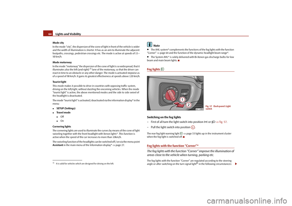
Switching on the fog lights – First of all turn the light switch into position
or
⇒
fig. 57
.
– Pull the light switch into position .The rear fog light warning light
⇒page 33 lights up in the instrument cluster
when the fog light is switched off.Fog lights with the function “Corner”* The fog lights with the function “C
orner” improve the illumination of
areas close to the vehicle when turning, parking etc.The fog lights with the function “Corner” are regulated according to the steering angle or after switching on the turn signal light
8) in the following circumstances:
7)It is valid for vehicles which are designed for driving on the left.
Fig. 57 Dash panel: Light switch
A1
s2dk.1.book Page 64 Wednesday, April 8, 2009 12:23 PM
Page 84 of 294

Seats and Stowage
83
Using the system
Safety
Driving Tips
General Maintenance
Breakdown assistance
Technical Data
Removing and installing a head restraint – Pull the head restraint up out of the seat backrest as far as the stop (on
the rear head restraints fold forward the seat backrest).
– Press the locking button in the direction of arrow
⇒
page 82, fig. 82
and pull the head restraint out.
– To re-insert the head restraint, push it down into the seat backrest far
enough until you hear the locking button engage.
The position of the front and rear outer head
restraints is adjustable in height. The
middle rear head restraint is adjustable in two positions. The head restraints must be adjusted to
match the size of the seat occupant.
Correctly adjusted head restraints together with the seat belts offer effective protection for the occupants
⇒page 164, “Correct seated position”.
WARNING
•
The head restraints must be correctly
adjusted in order to offer effective
protection for the occupants in the event of an accident.•
Do not drive under any circumstance with removed head restraints - risk
of injury!•
If the rear seats are occupied, the rear head restraint must not be in the
lower position.
Middle rear head restraintIIn certain countries national legal pr
ovisions also require the equipment
of the rear seat with fixing eyes for child seat using the “Top Tether” system ⇒
page 192, “Attaching child seat using the “Top Tether” system”. For
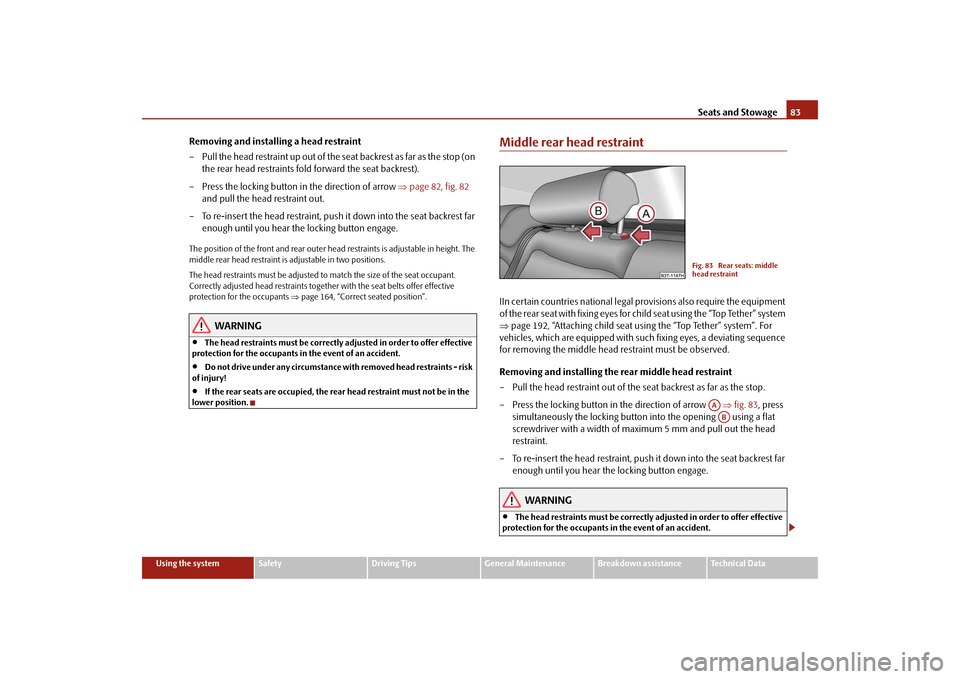
vehicles, which are equipped with such fixing eyes, a deviating sequence for removing the middle head restraint must be observed. Removing and installing the rear middle head restraint – Pull the head restraint out of the seat backrest as far as the stop. – Press the locking button in the direction of arrow
⇒
fig. 83
, press
simultaneously the locking button into the opening using a flat screwdriver with a width of maximum 5 mm and pull out the head restraint.
– To re-insert the head restraint, push it down into the seat backrest far
enough until you hear the locking button engage.
WARNING
•
The head restraints must be correctly adjusted in order to offer effective
protection for the occupants in the event of an accident.
Fig. 83 Rear seats: middle head restraint
AAAB
s2dk.1.book Page 83 Wednesday, April 8, 2009 12:23 PM
Page 238 of 294

Wheels and Tyres
237
Using the system
Safety
Driving Tips
General Maintenance
Breakdown assistance
Technical Data
Changing wheels aroundIf significantly greater wear is present on the front tyres, we recommend changing the front wheels around with the rear wheels as shown in the diagram
⇒fig. 212
.
You will then obtain approximately the same life for all the tyres. It may be advantageous to swap the tyre
s over “crosswise” when certain types of
wear characteristic arise on
the running surface of the tyres (but not in the case of
unidirectional tyres). The co-workers of the authorised Škoda Service Partners are extensively familiar with the combination possibilites. We recommend that you change the wheels around every 10 000 km in order to achieve even wear on all wheels and to obtain optimal tyre life.New tyres and wheelsTyres and wheel rims are important design
elements. One should therefore use the
tyres and wheel rims which have been released for use by Škoda Auto. They are exactly matched to the vehicle type and th
erefore contribute significantly to good
road holding and safe driving characteristics
⇒
.
Only fit radial tyres of the same type on
all 4 wheels, size (rolling circumference)
and, if possible, the same tread pattern on one axle. The authorised Škoda Service Partners have access to the most current information about which tyres we have rele
ased for use on your vehicle.
We recommend that you have any work rela
ting to tyres or wheels carried out by
an authorised Škoda Service Partner
. The authorised Škoda Service Partners
have all of the necessary special tools
and replacement parts available plus the
required specialist knowledge and are also in a position to properly dispose of the old tyres. A large number of authorised Škod
a Service Partners also have an attrac-
tive range of tyres and wheels available. The tyre/wheel combinations which are appr
oved for your vehicle are indicated in
your vehicle documents. Approval and lice
nsing may differ according to the legis-
lation prevailing in individual countries. Proper knowledge of the tyre data makes it easier for you to select the correct type of tyre. Tyres do, for example, have the following
inscription
on their walls:
205 / 55 R 16 94 V
What this means is: The following
speed restrictions
apply to tyres.
Fig. 212 Changing wheels around
205
Tyre wid th i n m m
55
Height/width ratio in %
R
Code letter for the type of tyre -
R adial
16
Diameter of wheel in inches
94
Load index
V
Speed symbol
Speed symbol
Permissible maximum speed
S
180 km/h
T
190 km/h
H
210 km/h
V
240 km/h
W
270 km/h
Y
300 km/h
s2dk.1.book Page 237 Wednesday, April 8, 2009 12:23 PM
Page 240 of 294

Wheels and Tyres
239
Using the system
Safety
Driving Tips
General Maintenance
Breakdown assistance
Technical Data
Winter tyresThe handling of your vehicle will be significantly improved when driving on wintry roads if you fit winter tyres. Summer tyres do not offer the same grip on ice, snow and at temperatures below 7 °C because of
their construction (width, rubber blend,
tread pattern). This partic
ularly applies to vehicles
which are equipped with
low-
profile tyres
or high-speed tyres
(code index H or V on wall of tyre).
Winter tyres must be mounted on all four wheels to obtain the best handling char- acteristics. You must only fit those types of winter tyre which are approved for your vehicle. The permissible
sizes of winter tyres
are stated in your vehicle documents. Approvals
may differ because of national legislation. Please remember that the tyres should be in
flated to 20 kPa (0.2 bar) more than is
the case for summer tyres
⇒page 235, fig. 210
.
Winter tyres no longer
offer the same winter performance once the
tyre tread
has
worn down to a depth of about 4 mm. Ageing
also causes winter tyres to lose most of their winter performance properties
- even in cases where the remaining tread depth is still clearly more than 4 mm. Speed restrictions
apply to winter tyres as well as to summer tyres
⇒page 237,
⇒
.
You can fit winter tyres of a lower speed ca
tegory to your vehicle provided that you
also do not drive faster than the permis
sible maximum speed fo
r such tyres, even
if the possible maximum speed of your ve
hicle is higher. The corresponding tyre
category can damage the tyres when ex
ceeding the permissi
ble maximum speed.
Please pay attention to the notes if
you decide to fit winter tyres
⇒page 235.
You can also fit so-called “all-year tyres” instead of winter tyres.Please contact your specialist garage if
there are any points which are not clear who
will be able to provide you with information regarding the maximum speed for your tyres.
WARNING
You must on no account drive your car at more than the permissible maximum speed for your winter tyres - risk of an accident resulting from tyre damage and loss of control over your car.
For the sake of the environment
Fit your summer tyres on again in good ti
me since summer tyres offer you better
grip and handling on roads which are free of snow and ice as well as ar tempera-tures below 7 °C - the braking distance is shorter, there is less tyre noise, tyre wear is reduced and fuel consumption is reduced.
Note
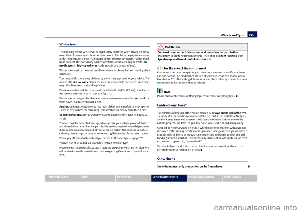
Please observe the various differing legal requirements regarding tyres.Unidirectional tyres*The direction of rotation of the tyres is marked by
arrows on the wall of the tyre
.
This indicates the direction of rotation of the tyre, and it is essential that the tyres are fitted on to run in this direction. Only then are the tyres able to provide the optimal properties in terms of grip, low noise, wear-and-tear and aquaplaning. Should it be necessary to fit on a spare
wheel in exceptional cases with a tyre not
dedicated to the running dire
ction or in opposite running
direction, please adopt a
cautious style of driving as the tyre is no
longer able to provide optimal grip and
handling in such a situation.
This particularly important
on wet roads. Please refer
to the notes
⇒page 245, “Spare wheel*”.
You should have the defective tyre replac
ed as soon as possible and restore the
correct direction of rotation on all tyresSnow chainsSnow chains must only be mounted on the front wheels.
s2dk.1.book Page 239 Wednesday, April 8, 2009 12:23 PM
Page 270 of 294

Technical Data
269
Using the system
Safety
Driving Tips
General Maintenance
Breakdown assistance
Technical Data
Combined traffic The consumption value in the combined traf
fic consists of 37%
from the value for
the urban traffic and of 63% from
the value for the non-urban traffic.
Note
•
Please note that the information stated in the
official vehicle registration
documents
always takes priority.
DimensionsDimensions (mm)Length
4838/4849
a)
a)The value corresponds to the status
with visual appearance package.
Width
1817
Width including
exterior mirror
2009
Height
1462/1482
b)/1447
c)
b)The value corresponds to the status with rough road package.c)The value corresponds to the status with sport chassis.Clearance
139/158
b)/123
c)
Wheel base
2761
Tr a c k g a u g e f r o n t / r e a r
1545/1518 1537/1510
d)
1545/1517
e)
d)Valid for vehicles with 3.6°ltr./191°kW FSI engine.e)Superb GreenLine.
s2dk.1.book Page 269 Wednesday, April 8, 2009 12:23 PM