buttons SKODA SUPERB 2010 2.G / (B6/3T) Owner's Manual
[x] Cancel search | Manufacturer: SKODA, Model Year: 2010, Model line: SUPERB, Model: SKODA SUPERB 2010 2.G / (B6/3T)Pages: 287, PDF Size: 16.59 MB
Page 10 of 287
Cockpit9
Using the system
Safety
Driving Tips
General Maintenance
Breakdown assistance
Technical Data
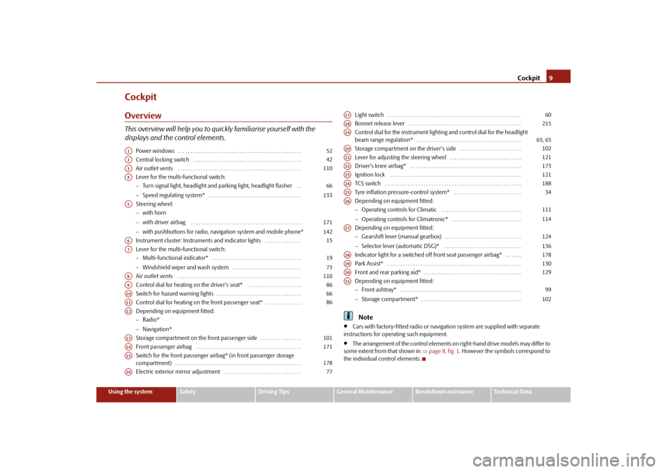
CockpitOverviewThis overview will help you to quic kly familiarise yourself with the
displays and the control elements.
Power windows . . . . . . . . . . . . . . . . . . . . . . . . . . . . . . . . . . . . . . . . . . . . . . . .
Central locking switch . . . . . . . . . . . . . . . . . . . . . . . . . . . . . . . . . . . . . . . . . .
Air outlet vents . . . . . . . . . . . . . . . . . . . . . . . . . . . . . . . . . . . . . . . . . . . . . . . .
Lever for the multi-functional switch:
Turn signal light, headlight and parking light, headlight flasher . .
Speed regulating system* . . . . . . . . . . . . . . . . . . . . . . . . . . . . . . . . . . . .
Steering wheel:
with horn
with driver airbag . . . . . . . . . . . . . . . . . . . . . . . . . . . . . . . . . . . . . . . . . . .
with pushbuttons for radio, navi gation system and mobile phone*
Instrument cluster: Instruments and indicator lights . . . . . . . . . . . . . .
Lever for the multi-functional switch:
Multi-functional indicator* . . . . . . . . . . . . . . . . . . . . . . . . . . . . . . . . . . .
Windshield wiper and wash system . . . . . . . . . . . . . . . . . . . . . . . . . . .
Air outlet vents . . . . . . . . . . . . . . . . . . . . . . . . . . . . . . . . . . . . . . . . . . . . . . . .
Control dial for heating on the driver's seat* . . . . . . . . . . . . . . . . . . . . .
Switch for hazard warning lights . . . . . . . . . . . . . . . . . . . . . . . . . . . . . . . . .
Control dial for heating on the front passenger seat* . . . . . . . . . . . . . .
Depending on equipment fitted:
Radio*
Navigation*
Storage compartment on the front passenger side . . . . . . . . . . . . . . . .
Front passenger airbag . . . . . . . . . . . . . . . . . . . . . . . . . . . . . . . . . . . . . . . . .
Switch for the front passenger ai rbag* (in front passenger storage
compartment) . . . . . . . . . . . . . . . . . . . . . . . . . . . . . . . . . . . . . . . . . . . . . . . . .
Electric exterior mirror adjustment . . . . . . . . . . . . . . . . . . . . . . . . . . . . . . Light switch . . . . . . . . . . . . . . . . . . . . . . . . . . . . . . . . . . . . . . . . . . . . . . . . . . . .
Bonnet release lever . . . . . . . . . . . . . . . . . . . . . . . . . . . . . . . . . . . . . . . . . . . .
Control dial for the instrument lighting and control dial for the headlight
beam range regulation* . . . . . . . . . . . . . . . . . . . . . . . . . . . . . . . . . . . . . . . . .
Storage compartment on the driver's side . . . . . . . . . . . . . . . . . . . . . . . .
Lever for adjusting the steering wheel . . . . . . . . . . . . . . . . . . . . . . . . . . . .
Driver's knee airbag* . . . . . . . . . . . . . . . . . . . . . . . . . . . . . . . . . . . . . . . . . . .
Ignition lock . . . . . . . . . . . . . . . . . . . . . . . . . . . . . . . . . . . . . . . . . . . . . . . . . . .
TCS switch . . . . . . . . . . . . . . . . . . . . . . . . . . . . . . . . . . . . . . . . . . . . . . . . . . . . .
Tyre inflation pressure-control system* . . . . . . . . . . . . . . . . . . . . . . . . . .
Depending on equipment fitted:
Operating controls for Climatic . . . . . . . . . . . . . . . . . . . . . . . . . . . . . . .
Operating controls for Climatronic* . . . . . . . . . . . . . . . . . . . . . . . . . . .
Depending on equipment fitted:
Gearshift lever (manual gearbox) . . . . . . . . . . . . . . . . . . . . . . . . . . . . . .
Selector lever (automatic DSG)* . . . . . . . . . . . . . . . . . . . . . . . . . . . . . .
Indicator light for a switched off front seat passenger airbag* . . . . . .
Park Assist* . . . . . . . . . . . . . . . . . . . . . . . . . . . . . . . . . . . . . . . . . . . . . . . . . . . .
Front and rear parking aid* . . . . . . . . . . . . . . . . . . . . . . . . . . . . . . . . . . . . . .
Depending on equipment fitted:
Front ashtray* . . . . . . . . . . . . . . . . . . . . . . . . . . . . . . . . . . . . . . . . . . . . . . .
Storage compartment* . . . . . . . . . . . . . . . . . . . . . . . . . . . . . . . . . . . . . . .
Note
Cars with factory-fitted radio or naviga tion system are supplied with separate
instructions for operating such equipment.
The arrangement of the control elements on right-hand drive models may differ to
some extent from that shown in page 8, fig. 1 . However the symbols correspond to
the individual control elements.
A1
52
A2
42
A3
110
A4
66133
A5
171142
A6
15
A7
1973
A8
110
A9
86
A10
66
A11
86
A12A13
101
A14
171
A15
178
A16
77
A17
60
A18
215
A19
65, 65
A20
102
A21
121
A22
173
A23
121
A24
188
A25
34
A26
111114
A27
124136
A28
178
A29
130
A30
129
A31
99102
s3fg.2.book Page 9 Friday, April 30, 2010 12:17 PM
Page 14 of 287
The brief instruction13
Using the system
Safety
Driving Tips
General Maintenance
Breakdown assistance
Technical Data
Slow wipe
Fast wipe
one time wipe
Automatic wipe/wash
Rear window wiper Intermittent wipe - every 6 seconds
Automatic wipe/wash
Further information page 73, “Windshield wiper and wash system”.
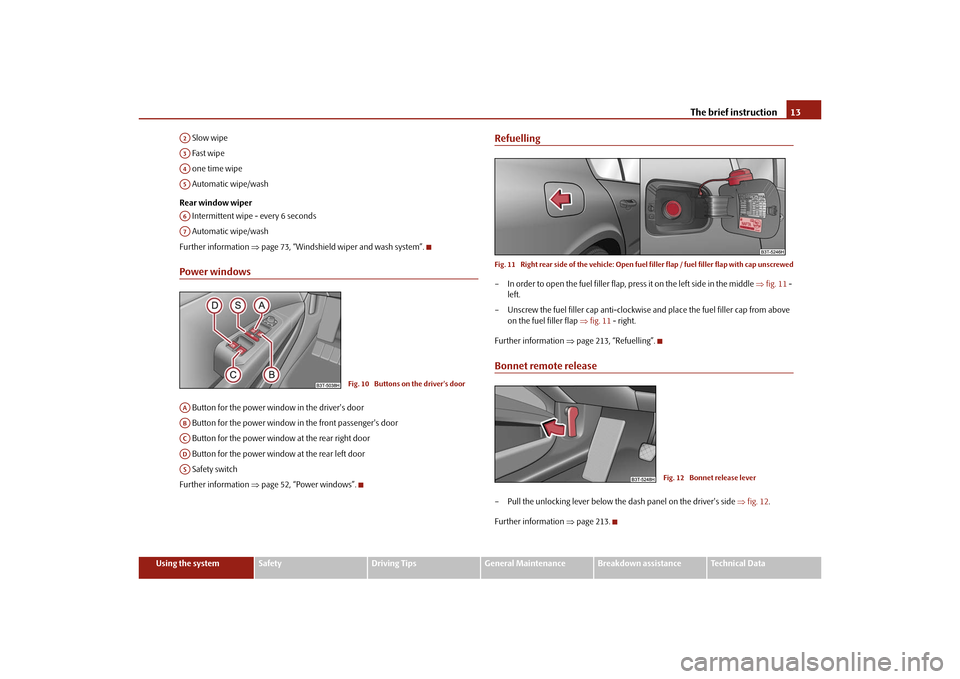
Power windows Button for the power window in the driver's door
Button for the power window in the front passenger's door
Button for the power window at the rear right door
Button for the power window at the rear left door
Safety switch
Further information page 52, “Power windows”.
RefuellingFig. 11 Right rear side of the ve hicle: Open fuel filler flap / fuel filler flap with cap unscrewed– In order to open the fuel filler flap, press it on the left side in the middle fig. 11 -
left.
– Unscrew the fuel filler ca p anti-clockwise and place the fuel filler cap from above
on the fuel filler flap fig. 11 - right.
Further information page 213, “Refuelling”.Bonnet remote release– Pull the unlocking lever below the dash panel on the driver's side fig. 12 .
Further information page 213.
A2A3A4A5A6A7
Fig. 10 Buttons on the driver's door
AAABACADAS
Fig. 12 Bonnet release lever
s3fg.2.book Page 13 Friday, April 30, 2010 12:17 PM
Page 19 of 287
Instruments and warning lights
18
On vehicles which are equipped with inform ation display*, you can call up this infor-
mation in the following menu on page 23:
SETUP
Service Interval (Service)
Info
The following will be displayed in the information display* for 10 seconds: Service in ... km or ... days
Resetting Service Interval Display
It is only possible to reset the Service Interval Display, if a service message or at least a
pre-warning is shown on the display of the instrument cluster.
We recommend having this resetting performed by a specialist garage.
The specialist garage:
resets the memory of the display after the appropriate inspection,
makes an entry in the Service schedule,
affix the sticker with the entry of the following service interval to the side of the
dash panel on the driver's side.
Reset the service interval displays by using the reset button page 15 on the trip
counter.
On vehicles which are equipped with inform ation display*, you can call up this infor-
mation in the following menu on page 23:
SETUP
Service Interval (Service)
ResetCaution
We recommend that you do not reset the Se rvice Interval Display yourself otherwise
this can result in the service interval display being incorrectly set, which may also result
in problems with operation of your vehicle.
Note
Never reset the display between service intervals otherwise this may result in
incorrect readouts.
information is retained in the Service Inter val Display also after the battery of the
vehicle is disconnected.
If the instrument cluster is exchanged after a repair, the correct values must be
entered in the counter for the Service Interva l Display. This work is carried out by a
specialist garage.
The data displayed is the same after resetting the display with flexible service inter-
vals (QG1) using the reset button as that for a vehicle with fixed service intervals (QG2).
We therefore recommend having the Service In terval Display reset only by an author-
ised Škoda Service Partner who is familiar with the procedure for resetting the display
with a vehicle system tester.
Please refer to the brochure Service schedule for extensive information about the
service intervals.
Digital clockThe time is set with the buttons and page 15, fig. 15 .
Select the display which you wish to ch ange with the button and carry out the
change with the button .
On vehicles which are fitted out with the information display*, it is possible to set the
time in the menu Time page 25.
WARNING
The clock should not be adjusted while driving for safety reasons but only when
the vehicle is stationary!
A7
A3
A7
A3
A7
s3fg.2.book Page 18 Friday, April 30, 2010 12:17 PM
Page 21 of 287
Instruments and warning lights
20
The multi-functional indicator is equi pped with two automatic memories. The
selected memory is displayed in the middle of the display field page 19, fig. 18 .
The data of the single-trip memory (memory 1) is shown if a 1 appears in the display.
A 2 shown in the display means that data relates to the total distance memory
(memory 2).
Switching over the memory with the help of the button fig. 19 on the windscreen
wiper lever or with the help of the button on the multifunction steering wheel*
fig. 19 .
Single-trip memory (memory 1)
The single-trip memory collates the driving information from the moment the ignition
is switched on until it is switched off. New data will also flow into the calculation of the
current driving information if the trip is continued within 2 hours after switching off
the ignition. The memory will be is automatically erased, on the other hand, if the trip
is interrupted for more than 2 hours .
Total-trip memory (memory 2)
The total distance driven memory gathers data from any number of individual jour-
neys up to a total of 19 hours and 59 minut es driving or 1.999 kilometres driven and
on vehicles which are fitted wi th information display* up to a total of 99 hours and 59
minutes driving or 9.999 kilometres driven. The memory is deleted when either of
these limits is reached and the calculation starts from anew.
The total-trip memory will not, contrary to the single-trip memory, be deleted after a
period of interr uption of driving of 2 hours.
Note
All information in the memory 1 and 2 is erased if the battery of the vehicle is
disconnected.
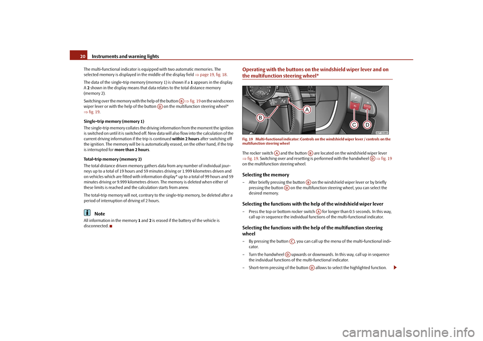
Operating with the buttons on the windshield wiper lever and on the multifunction steering wheel*Fig. 19 Multi-functional indica tor: Controls on the windshield wiper lever / controls on the
multifunction steering wheelThe rocker switch and the button are located on the windshield wiper lever
fig. 19 . Switching over and resetting is performed with the handwheel fig. 19
on the multifunction steering wheel.Selecting the memory– After briefly pressing the button on the windshield wiper lever or by briefly
pressing the button on the multifunc tion steering wheel, you can select the
desired memory.Selecting the functions with the help of the windshield wiper lever– Press the top or bottom rocker switch for longer than 0.5 seconds. In this way,
call up in sequence the individual func tions of the multi-functional indicator.Selecting the functions with the help of the multifunction steering
wheel– By pressing the button , you can call up the menu of the multi-functional indi-
cator.
– Turn the handwheel upwards or downward s. In this way, call up in sequence
the individual functions of th e multi-functional indicator.
– Short-term pressing of the button allows to select the highlighted function.
AB
AD
AA
AB
AD
AB
AD
AA
AC
AD
AD
s3fg.2.book Page 20 Friday, April 30, 2010 12:17 PM
Page 24 of 287
Instruments and warning lights23
Using the system
Safety
Driving Tips
General Maintenance
Breakdown assistance
Technical Data
Information display*IntroductionThe information display provides you with information in a convenient way
concerning the current operating state of your vehicle . The information system also
provides you with data (depending on the equipment installed in the vehicle) relating
to the radio, mobile phone, multi-function al indicator, navigation system and auto-
matic gearbox.
Certain functions and operating conditions are always being checked on the vehicle
when the ignition is switched on and also while driving.
Functional faults, if required repair work and other information are indicated by red
symbols page 24 and yellow symbols page 25.
Lighting up of certain symbols is comb ined with an acoustic warning signal.
Information and texts giving warnings are also shown in the display page 27.
The display of text is possible in the following languages: Czech, English, German, French, Italian, Spanish, Portuguese, Russian and Chinese.
You can select the desired language in the setting menu.
The following information can be shown in the display (depending on the equipment
installed on the vehicle):
Caution
Pull out the ignition key while having contact with the display (for example when
cleaning) in order to prevent any damage.
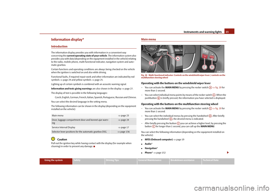
Main menuFig. 20 Multi-functional indica tor: Controls on the windshield wiper lever / controls on the
multifunction steering wheelOperating with the buttons on the windshield wiper lever– You can activate the MAIN MENU by pressing the rocker switch fig. 20 for
more than 1 second.
– You can select indivi dual menu points by means of the rocker switch . When the
pushbutton is briefly pressed, the information you have selected is displayed.Operating with the buttons on the multifunction steering wheel– You can activate the MAIN MENU by pressing the rocker switch fig. 20 for
more than 1 second.
– You can select the individual menus by pressing the handwheel . After briefly
pressing the handwheel , th e desired menu is indicated.
– After briefly pressing the button you can achieve a higher level, by pressing the
button for longer than 1 second, you can call up the MAIN MENU.
You can select the following information (d epending on the equipment installed on
the vehicle):
MFD (Onboard computer) page 19
Audio *
Navigation *
Phone* page 152
Main menu
page 23
Door, luggage compartment door and bonnet ajar warn-
ing
page 24
Service Interval Display
page 17
Selector lever positions fo r the automatic gearbox DSG
page 136
AAAA
AB
ACAD
AD
AC
AC
s3fg.2.book Page 23 Friday, April 30, 2010 12:17 PM
Page 40 of 287
Unlocking and locking39
Using the system
Safety
Driving Tips
General Maintenance
Breakdown assistance
Technical Data
unlocked when opening. Afterwards you can open the boot lid by pressing the handle
on the lower edge of the boot lid
page 44.
Operation of the central locking system is possible:
with a remote control key page 49,
using the buttons for the central locking system page 42,
from the outside using the vehicle key page 43, “Emergency unlocking and
locking of the driver's door”.
Indicator light in the driver's door
After locking the vehicle the indicator light fl ashes for 2 seconds fast, then more slowly.
If the vehicle is locked and the safe securing system page 42 is not operating, the
indicator light in the driver door flashes for about 2 seconds fast, goes out and starts to
flash slowly after about 30 seconds.
If the indicator light first of all flashes fast for about 2 seconds, afterwards lights up for
about 30 seconds without interruption and th en flashes slowly, there is a fault in the
system of the central locking or in the inte rior monitor and in the towing protection
monitoring* page 51. Visit a specialist garage to obtain assistance.
Convenience operatio n of the windows
One can open and close the windows when opening and closing the vehicle
page 54.
Opening a single door*
This function makes it possible to only unlock the driver's door. The other doors and
the fuel filler flap remain locked and ar e only unlocked after repetitive unlocking.
You can have the function opening a single door activated by an authorised Škoda
Service Partner on request or you can activate it yourself with the aid of the Informa-
tion display* page 25.
Unlocking a vehicle side door*
This selection function enables to unlock both doors on the driver's side. The other
doors and the fuel filler flap remain locked and are only unlocked after repetitive
unlocking. You can have the function opening a single
door activated by an authorised Škoda
Service Partner on request or you can activate it yourself with the aid of the Informa-
tion display* page 25.
Unlocking the vehicle with the KESSY system*
This selection function enables to unlock all th e doors, individual doors, both doors on
the left and right vehicle side or to unlock the driver and front passenger door at the
same time. The other doors and the fuel fille r flap remain locked and are only unlocked
after repetitive unlocking using the unlock button on the remote control page 37,
fig. 23 or the button for the central locking system page 42, fig. 27 .
You can have the function opening a single door activated by an authorised Škoda
Service Partner on request or you can activate it yourself with the aid of the Informa-
tion display* page 25.
Automatic locking and unlocking*
All the doors and the boot lid are locked au tomatically once the car reaches a speed of
about 15 km/h.
If the ignition key is withdrawn, the car is then automatically unlocked again. In addi-
tion, it is possible for the driver or front pa ssenger to unlock the vehicle by pressing the
central locking button
page 42 or by pulling the door opening lever on one of the
front doors.
You can have the function of the automatic lo cking activated by a specialist garage on
request or you can also activate it yourself with the aid of the Information display*
page 25.
WARNING
Locking the doors prevents involuntary op ening in an exceptional situation (an
accident). Locked doors prevent unwanted entry into the vehicle from outside,
for example at road crossings. Locked do ors do, however, make it more difficult
for rescuers to get into the vehicle in an emergency - danger to life!
Note
In the event of an accident in which the airbags are deployed, the locked doors are
automatically unlocked in order to enable rescuers to gain access to the vehicle.
s3fg.2.book Page 39 Friday, April 30, 2010 12:17 PM
Page 44 of 287
Unlocking and locking43
Using the system
Safety
Driving Tips
General Maintenance
Breakdown assistance
Technical Data
WARNING
The central locking system al so operates if the ignition is switched off. All the
doors and the boot lid are locked. Childr en should never be left unattended in
the vehicle since it is difficult to prov ide assistance from the outside when the
doors are locked. Locked doors make it difficult for rescuers to get into the
vehicle in an emergency - hazard!
Note
The door opening lever and the buttons for the central locking system do not operate
if the safe securing system is activated.Emergency unlocking and locking of the driver's door
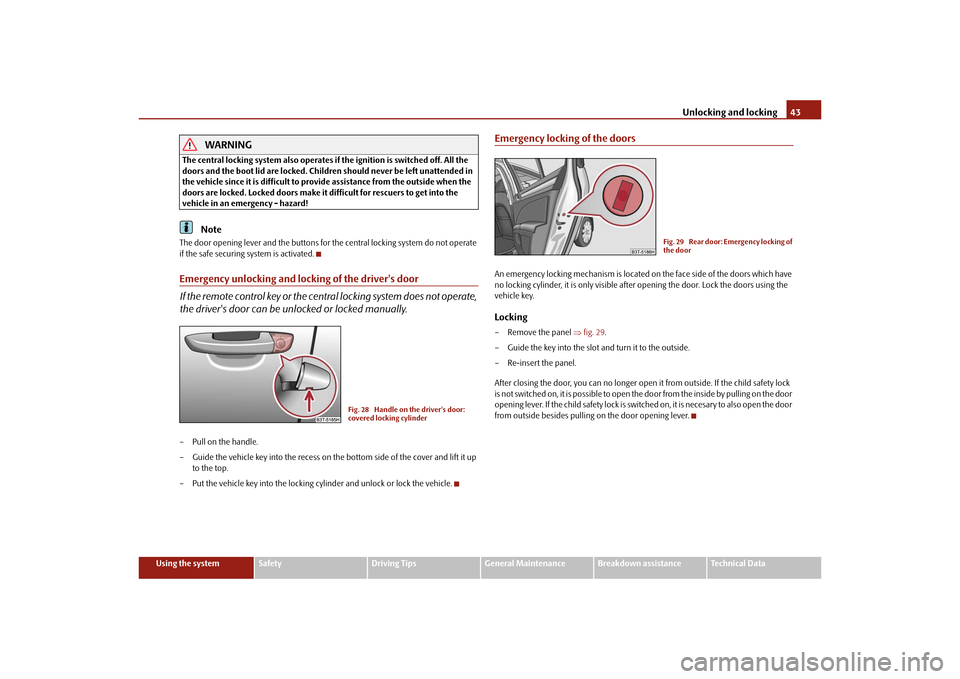
If the remote control key or the central locking system does not operate,
the driver's door can be unlocked or locked manually.– Pull on the handle.
– Guide the vehicle key into the recess on the bottom side of the cover and lift it up to the top.
– Put the vehicle key into the locking cy linder and unlock or lock the vehicle.
Emergency locking of the doorsAn emergency locking mechanism is located on the face side of the doors which have
no locking cylinder, it is only visible afte r opening the door. Lock the doors using the
vehicle key.Locking– Remove the panel fig. 29 .
– Guide the key into the slot and turn it to the outside.
– Re-insert the panel.
After closing the door, you can no longer open it from outside. If the child safety lock
is not switched on, it is possible to open the door from the inside by pulling on the door
opening lever. If the child safety lock is switch ed on, it is necesary to also open the door
from outside besides pulling on the door opening lever.
Fig. 28 Handle on the driver's door:
covered locking cylinder
Fig. 29 Rear door: Emergency locking of
the door
s3fg.2.book Page 43 Friday, April 30, 2010 12:17 PM
Page 53 of 287
Unlocking and locking
52Note
You can switch the interior monitor and th e towing protection monitoring off if
there is a possibility that movements from (e.g. children or animals) inside the vehicle
interior or if the vehicle must be transpor ted (e.g. by train or ship) or towed, might
trigger the alarm.
The opened storage compartment for spectacles* reduces the effectiveness of the
interior monitor. In order to ensure the function of the interior monitor to be fully
operational, always close the storage comp artment for spectacles before locking the
vehicle.
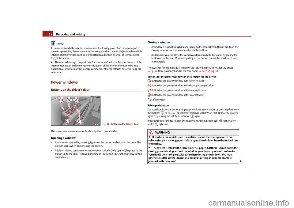
Power windowsButtons on the driver's doorThe power windows operate only when ignition is switched on.Opening a window – A window is opened by pressing lightly on the respective button in the door. The
process stops when one releases the button.
– Additionally you can open the window auto matically (fully opened) by pressing the
button up to the stop. Renewe d pressing of the button causes the window to stop
immediately.
Closing a window– A window is closed through pulling lightly on the respective button in the door. The closing process stops when one releases the button.
– Additionally you can close the window automatically (fully closed) by pulling the button up to the stop. Renewed pulling of the button causes the window to stop
immediately.
The switches for the individual windows are located in the armrest for the driver
fig. 39 , front passenger and in the rear doors page 53, fig. 40 .
Buttons for the power windows in the armrest for the driver
Button for the power window in the driver's door
Button for the power window in the front passenger's door
Button for the power window at the rear right door
Button for the power window at the rear left door
Safety switch
Safety pushbutton
You can deactivate the buttons for power wind ows at rear doors by pressing the safety
pushbutton fig. 39 . The buttons for power windows at rear doors are activated
again by pressing the safety pushbutton again.
If the buttons for the rear doors are deactivated, the indicator light
in the safety
switch lights up.
WARNING
If you lock the vehicle from the outside, do not leave any person in the
vehicle since it is no longer possible to open the windows from the inside in an
emergency.
The system is fitted with a force limiter page 53. If there is an obstacle, the
closing process is stopped and the window goes down by several centimeters.
You should then take particular care when closing the windows! You may
otherwise suffer severe injuries as a re sult of getting an arm, for example,
jammed in the window!
Fig. 39 Buttons on the driver's door
AAABACADAS
AS
AS
AS
s3fg.2.book Page 52 Friday, April 30, 2010 12:17 PM
Page 59 of 287

Unlocking and locking
58
Opening and closing the sun screenYou can open or close the sun screen se parately with the aid of the buttons fig. 44 .Opening– Briefly press the button fig. 44 in order to fully open.
– Press the button and hold it pressed in order to open in the desired position.
The opening process stops when one releases the button.Closing– Briefly press the button fig. 44 in order to fully close.
– Press the button and hold it pressed in order to close in the desired position.
The closing process stops when one releases the button.Convenience operationThe panoramic sliding roof and the sun screen can also be operated from the outside
using the remote control key or when using the KESSY* system with the aid of the
sensor page 40, fig. 26.Closing the panoramic sliding roof– Hold down the lock button on the remote control key, or when using the KESSY*
system keep your finger on the sensor page 40, fig. 26 , until the panoramic
sliding roof is closed. The panoramic sliding roof and the sun screen are closed
together. After releasing the button, or lifting your
finger off the sensor when using the
KESSY* system, the closing process is immediately interrupted.
Tilting the panoramic sliding roof– Hold down the unlock button on the remote control key until the panoramic sliding roof is tilted. When tilting the panoramic sliding roof, the sun screen opens at the
same time.
Note
The force limiter also operates for convenience closing.
The panoramic sliding roof can only be tilted but not opened when the conven-
ience operating feature is being used.
Emergency operationFig. 45 Detail of the headliner: Points fo r positioning screwdriver / emergency operationYou can close and/or open the panoramic slid ing roof by hand if the system is defec-
tive.
– Position the flat blade of a screwdriver carefully against the rear edge of the cover of the electrical drive fig. 45 .
–Pull the cover down.
– Insert an Allen key, Group 4, up to the stop into the opening and close or open the panoramic sliding roof.
Fig. 44 Buttons for sun screen
AE
AE
AF
AF
A1
A1
A1
AA
AB
s3fg.2.book Page 58 Friday, April 30, 2010 12:17 PM
Page 83 of 287
Seats and Stowage
82
The seat backrests must not be angled too far back when driving otherwise
this will affect proper operation of the se at belts and of the airbag system - risk
of injury!Note
If the movement of the seat is inadvertently interrupted during an adjustment, once
again press the switch in the appropriate di rection and continue with the adjustment
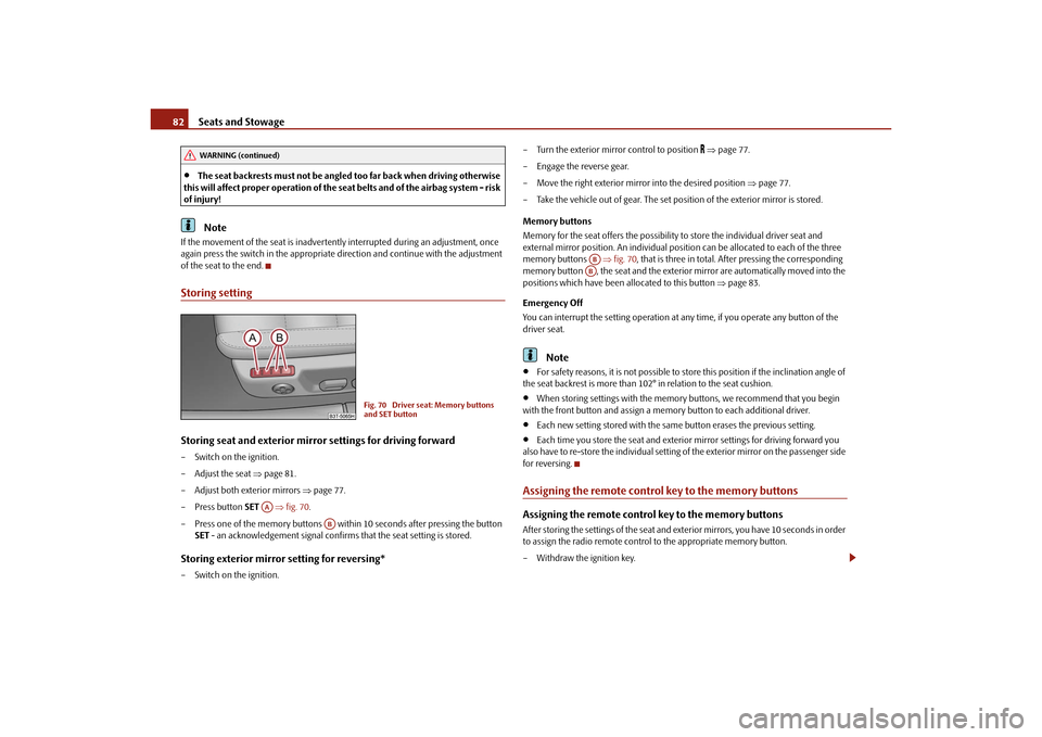
of the seat to the end.Storing settingStoring seat and exterior mirror settings for driving forward– Switch on the ignition.
– Adjust the seat page 81.
– Adjust both exterior mirrors page 77.
– Press button SET fig. 70 .
– Press one of the memory buttons within 10 seconds after pressing the button SET - an acknowledgement signal confirms that the seat setting is stored.Storing exterior mirror setting for reversing*– Switch on the ignition. – Turn the exterior mirror control to position
page 77.
– Engage the reverse gear.
– Move the right exterior mirror into the desired position page 77.
– Take the vehicle out of gear. The set position of the exterior mirror is stored.
Memory buttons
Memory for the seat offers the possibility to store the individual driver seat and
external mirror position. An individual posi tion can be allocated to each of the three
memory buttons fig. 70 , that is three in total. Af ter pressing the corresponding
memory button , the seat and the exterior mirror are automatically moved into the
positions which have been allocated to this button page 83.
Emergency Off
You can interrupt the setting operation at any time, if you operate any button of the
driver seat.
Note
For safety reasons, it is not possible to store this position if the inclination angle of
the seat backrest is more than 102 ° in relation to the seat cushion.
When storing settings with the memory buttons, we recommend that you begin
with the front button and assign a memory button to each additional driver.
Each new setting stored with the same button erases the previous setting.
Each time you store the seat and exterior mirror settings for driving forward you
also have to re-store the individual setting of the exterior mirror on the passenger side
for reversing.
Assigning the remote contro l key to the memory buttonsAssigning the remote control key to the memory buttonsAfter storing the settings of the seat and exterior mirrors, you have 10 seconds in order
to assign the radio remote control to the appropriate memory button.
– Withdraw the ignition key.
WARNING (continued)
Fig. 70 Driver seat: Memory buttons
and SET button
AA
AB
ABAB
s3fg.2.book Page 82 Friday, April 30, 2010 12:17 PM