heater SKODA SUPERB 2010 2.G / (B6/3T) Owner's Manual
[x] Cancel search | Manufacturer: SKODA, Model Year: 2010, Model line: SUPERB, Model: SKODA SUPERB 2010 2.G / (B6/3T)Pages: 287, PDF Size: 16.59 MB
Page 72 of 287
Lights and Visibility71
Using the system
Safety
Driving Tips
General Maintenance
Breakdown assistance
Technical Data
– Lever off the cover of the rechargeable ba
tteries with a narrow and pointed object
at the point of the lock-off clips page 70, fig. 58 .
– Remove the faulty rechargeable batteries from the lamp.
– Insert the new rechargeable batteries.
– Insert the cover of the rechargeable batteries and press on it until it is heard to lock
in place.
WARNING
Pay particular attention when using the narrow and pointed object to change
the rechargeable batteries - risk of injury.
Caution
We recommend having the faulty rechargeab le batteries replaced by a specialist
garage. If the lamp is not corr ectly opened, it can be damaged.
For the sake of the environment
Dispose of the faulty rechargeable batteries in accordance with environmental regula-
tions.
Note
Pay attention to the correct polarity wh en replacing the rechargeable batteries.
The replacement rechargeable batteries must have the same specification as the
original rechargeable batteries. If other ty pes of rechargeable batteries are used, the
power output can be reduced and it can lead to a malfunction of the lamp.
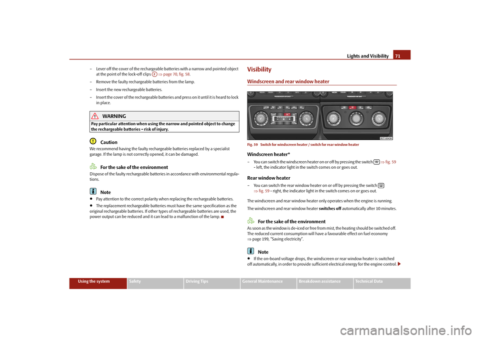
VisibilityWindscreen and rear window heaterFig. 59 Switch for windscreen heat er / switch for rear window heaterWindscreen heater*– You can switch the windscreen heater on or off by pressing the switch fig. 59
- left, the indicator light in th e switch comes on or goes out.Rear window heater– You can switch the rear window heater on or off by pressing the switch
fig. 59 - right, the indicator light in the switch comes on or goes out.
The windscreen and rear wind ow heater only operates when the engine is running.
The windscreen and rear window heater switches off automatically after 10 minutes.
For the sake of the environment
As soon as the window is de-iced or free from mist, the heating should be switched off.
The reduced current consumption will have a favourable effect on fuel economy
page 199, “Saving electricity”.
Note
If the on-board voltage drops, the windscre en or rear window heater is switched
off automatically, in order to provide sufficient electrical energy for the engine control.
AF
s3fg.2.book Page 71 Friday, April 30, 2010 12:17 PM
Page 73 of 287
Lights and Visibility
72
The position and the shape of the switch for rear window heater can differ
depending on the equipment installed in the vehicle.
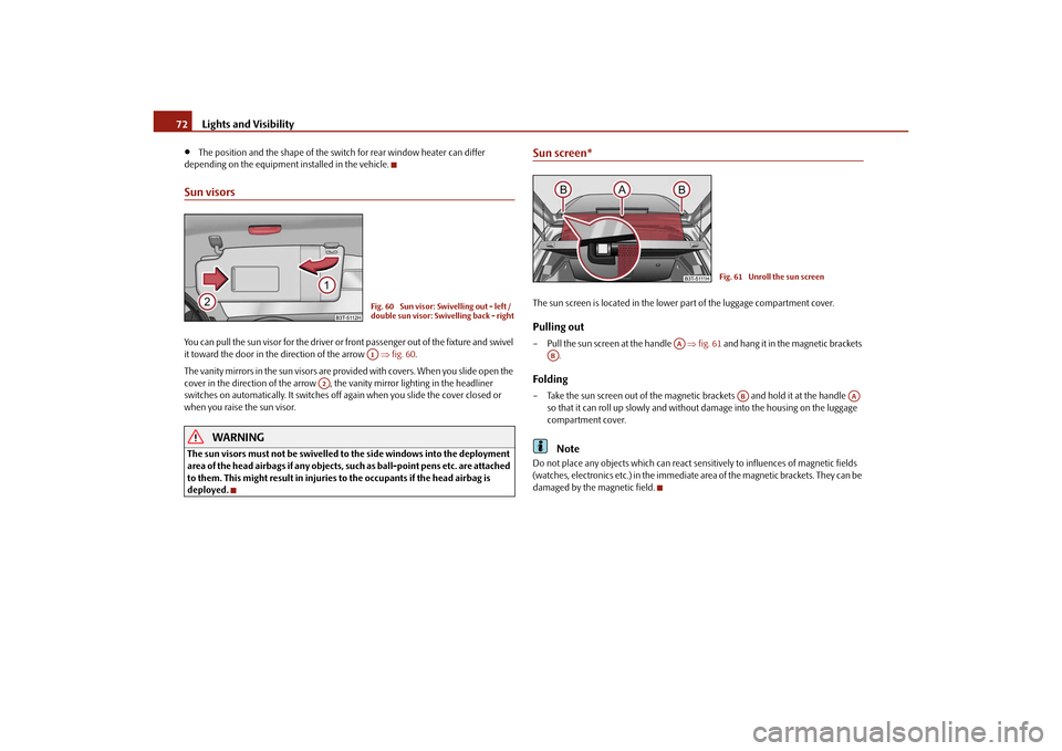
Sun visorsYou can pull the sun visor for the driver or front passenger out of the fixture and swivel
it toward the door in the direction of the arrow fig. 60 .
The vanity mirrors in the sun visors are provided with covers. When you slide open the
cover in the direction of the arrow , the vanity mirror lighting in the headliner
switches on automatically. It switches off again when you slide the cover closed or
when you raise the sun visor.
WARNING
The sun visors must not be swivelled to the side windows into the deployment
area of the head airbags if any objects, such as ball-point pens etc. are attached
to them. This might result in injuries to the occupants if the head airbag is
deployed.
Sun screen*The sun screen is located in the lower part of the luggage compartment cover.Pulling out– Pull the sun screen at the handle fig. 61 and hang it in the magnetic brackets
.Folding– Take the sun screen out of the magnetic brackets and hold it at the handle
so that it can roll up slowly and without damage into the housing on the luggage
compartment cover.
Note
Do not place any objects which can react sens itively to influences of magnetic fields
(watches, electronics etc.) in the immediate area of the magnetic brackets. They can be
damaged by the magnetic field.
Fig. 60 Sun visor: Swivelling out - left /
double sun visor: Swivelling back - rightA1
A2
Fig. 61 Unroll the sun screen
AA
AB
AB
AA
s3fg.2.book Page 72 Friday, April 30, 2010 12:17 PM
Page 78 of 287
Lights and Visibility77
Using the system
Safety
Driving Tips
General Maintenance
Breakdown assistance
Technical Data
Attaching a wiper blade– Position the wiper blade onto the wiper arm and lock the locking button .
– Check whether the wiper bl ade is correctly attached.
– Fold the windscreen wiper arm back onto the windscreen.
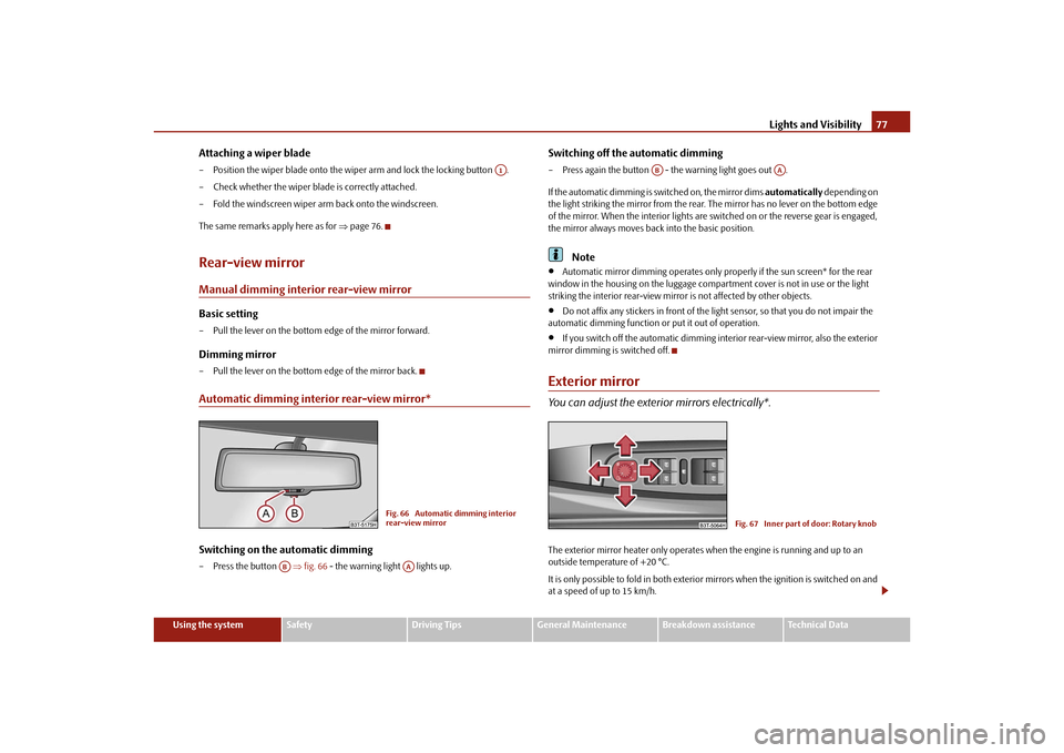
The same remarks apply here as for page 76.Rear-view mirrorManual dimming interior rear-view mirrorBasic setting– Pull the lever on the bottom edge of the mirror forward.Dimming mirror– Pull the lever on the bottom edge of the mirror back.Automatic dimming interior rear-view mirror*Switching on the automatic dimming– Press the button fig. 66 - the warning light lights up.
Switching off the automatic dimming– Press again the button - the warning light goes out .
If the automatic dimming is switched on, the mirror dims automatically depending on
the light striking the mirror from the rear. The mirror has no lever on the bottom edge
of the mirror. When the interior lights are switched on or the reverse gear is engaged,
the mirror always moves back into the basic position.
Note
Automatic mirror dimming operates only properly if the sun screen* for the rear
window in the housing on the luggage compartment cover is not in use or the light
striking the interior rear-view mirror is not affected by other objects.
Do not affix any stickers in front of the light sensor, so that you do not impair the
automatic dimming function or put it out of operation.
If you switch off the automatic dimming interior rear-view mirror, also the exterior
mirror dimming is switched off.
Exterior mirrorYou can adjust the exterior mirrors electrically*.The exterior mirror heater only operates when the engine is running and up to an
outside temperature of +20 °C.
It is only possible to fold in both exterior mirrors when the ignition is switched on and
at a speed of up to 15 km/h.
A1
Fig. 66 Automatic dimming interior
rear-view mirror
AB
AA
AB
AA
Fig. 67 Inner part of door: Rotary knob
s3fg.2.book Page 77 Friday, April 30, 2010 12:17 PM
Page 79 of 287
Lights and Visibility
78
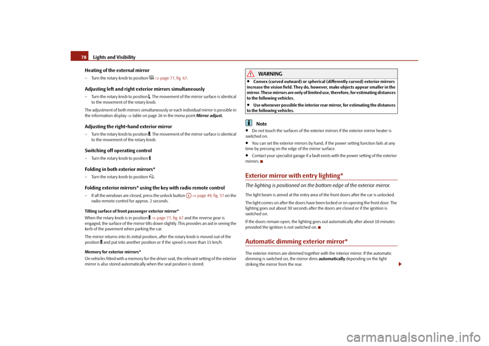
Heating of the external mirror
– Turn the rotary knob to position
page 77, fig. 67 .
Adjusting left and right exterior mirrors simultaneously– Turn the rotary knob to position
. The movement of the mirror surface is identical
to the movement of the rotary knob.
The adjustment of both mirrors simultaneously or each individual mirror is possible in
the information display table on page 26 in the menu point Mirror adjust.
Adjusting the right-hand exterior mirror– Turn the rotary knob to position
. The movement of the mirror surface is identical
to the movement of the rotary knob.
Switching off operating control– Turn the rotary knob to position
.
Folding in both exterior mirrors*– Turn the rotary knob to position
.
Folding exterior mirrors* using the key with radio remote control– If all the windows are clos ed, press the unlock button page 49, fig. 37 on the
radio remote control for approx. 2 seconds.
Tilting surface of front passenger exterior mirror*
When the rotary knob is in position
page 77, fig. 67 and the reverse gear is
engaged, the surface of the mirror tilts down slightly. This provides an aid in seeing the
kerb of the pavement when parking the car.
The mirror returns into its initial position, after the rotary knob is moved out of the
position
and put into another position or if the speed is more than 15 km/h.
Memory for exterior mirrors*
On vehicles fitted with a memory for the driver seat, the relevant setting of the exterior
mirror is also stored automatically when the seat position is stored.
WARNING
Convex (curved outward) or spherical (differently curved) exterior mirrors
increase the vision field. They do, however, make objects appear smaller in the
mirror. These mirrors are only of limited use, therefore, for estimating distances
to the following vehicles.
Use whenever possible the interior rear mirror, for estimating the distances
to the following vehicles.Note
Do not touch the surfaces of the exterior mirrors if the exterior mirror heater is
switched on.
You can set the exterior mirrors by hand, if the power setting function fails at any
time by pressing on the edge of the mirror surface.
Contact your specialist garage if a fault exists with the power setting of the exterior
mirrors.
Exterior mirror with entry lighting*The lighting is positioned on the bo ttom edge of the exterior mirror.The light beam is aimed at the entry area of the front doors after the car is unlocked.
The light comes on after the doors have been locked or on opening the front door. The
lighting goes out about 30 seconds after th e doors are closed or if the ignition is
switched on.
If the doors remain open, the lighting go es out automatically after about 10 minutes
provided the ignition is not switched on.Automatic dimming exterior mirror*The exterior mirrors are dimmed together with the interior mirror. If the automatic
dimming is switched on, the mirror dims automatically depending on the light
striking the mirror from the rear.
A3
s3fg.2.book Page 78 Friday, April 30, 2010 12:17 PM
Page 87 of 287
Seats and Stowage
86
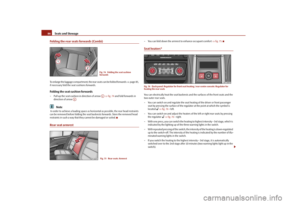
Folding the rear seats forwards (Combi)To enlarge the luggage compartment, the rear seats can be folded forwards page 85,
if necessary fold the seat cushions forwards.Folding the seat cushion forwards– Pull up the seat cushion in direction of arrow fig. 74 and fold forwards in
direction of arrow .
Note
In order to achieve a loading space as horizo ntal as possible, the rear head restraints
can be removed before folding the seat backrests forwards. Store the removed head
restraints in such a way that th ey cannot be damaged or soiled.Rear seat armrest
– You can fold down the armrest to enhance occupant comfort fig. 75 .Seat heaters*Fig. 76 Dash panel: Regulator for front seat heating / rear centre console: Regulator for
heating the rear seatsYou can electrically heat the seat backrests and the surfaces of the front seats and the
two outer rear seats.
– You can switch on and regulate the seat heating of the driver or front passenger
seat by pressing the surface of the regulator at the point at which the symbol is
located
fig. 76 - left.
– You can switch on and adjust the heaters of the left or right rear seats by pressing the regulator
fig. 76 - right.
– With one press, you can switch the heating to highest intensity - 3rd stage, which is
indicated by the lighting up of the three warning lights in the switch.
– With repeated pressing of the switch, the intensity of the heating is down-regulated up to the switch-off. The intensity of the heating is indicated by the number of illu-
minated warning lights in the switch.
– If you switch the heating to the highest intensity - 3rd stage, it is automatically switched over to the 2nd stage after 10 mi nutes (two warning lights light up in the
switch).
Fig. 74 Folding the seat cushion
forwardsA1
A2
Fig. 75 Rear seats: Armrest
s3fg.2.book Page 86 Friday, April 30, 2010 12:17 PM
Page 88 of 287
Seats and Stowage87
Using the system
Safety
Driving Tips
General Maintenance
Breakdown assistance
Technical Data
WARNING
If, as an occupant, you have a subdued pain and/or temp erature sensitivity, e.g.
through medication, paralysis or because of chronic illness (e.g. diabetes), we
recommend not to use the seat heating. Th is can lead to burns on the back, the
posterior and the legs which are difficult to heal. If the seat heating is used, we
recommend to make regular breaks in your journey when driving long
distances, so that in specific cases as mentioned above the body can recuperate
from the stress of the journey. Please consult your doctor, who can evaluate
your specific condition.
Caution
You should not kneel on the seats or otherwise apply pressure at specific points in
order to avoid damaging the heating elements of the seat heaters.
Do not use the seat heating if the seats are not occupied by persons or if objects
are fastened or stored on them, for example a child seat, a bag etc. A fault of the heating
elements in the seat heating can occur.
Do not clean the seats moist page 209.Note
The seat heating should only be switched on when the engine is running. This has
a significant effect of saving on the battery capacity.
If the on-board voltage drops, the seat heating is switched off automatically, in
order to provide sufficient electrical energy for the engine control.
PedalsConcerning a secure depressing of the peda l, you should use only footmats from the
Škoda genuine accessories.
Operation of the pedals must not be hindered!
WARNING
Greater pedal distances may be needed when there is a fault in the brake
system.
Do not place any footmats or other additional floor coverings in the area of
the pedals in order to ensure that all the pedals can be fully depressed and are
able to return unobstructed to their initial position - risk of accident!
There must be no objects on the floor which could roll under the pedals. You
would then no longer be able to apply the brakes, operate the clutch or acceler-
ator - risk of accident!
luggage compartmentLoading the luggage compartmentPlease observe the following in the interest of having good handling characteristics of
your vehicle:
– Distribute the items of luggage as evenly as possible.
– Place heavy objects as far forward as possible.
– Attach the items of luggage to the lashing eyes or the fixing net* page 88.
In the event of an accident, there is such a high kinetic energy which is produced by
small and light objects that they can cause severe injuries. The magnitude of the kinetic
energy depends on the speed at which the vehicle is travelling and on the weight of the
object. The speed at which the vehicle is trave lling is in this case the more significant
factor.
Example: In the event of a frontal collision at a speed of 50 km/h, an unsecured object
with a weight of 4.5 kg produces an en ergy, which corresponds to 20 times its own
weight. This means that it results in a weight of approx. 90 kg. You can imagine the inju-
ries that can occur, if this “bullet” is flying through the interior compartment and hits
an occupant.
WARNING
Stow the objects in the luggage compartment and attach them to the
lashing eyes.WARNING (continued)
s3fg.2.book Page 87 Friday, April 30, 2010 12:17 PM
Page 92 of 287

Seats and Stowage91
Using the system
Safety
Driving Tips
General Maintenance
Breakdown assistance
Technical Data
Caution
Please ensure that the heating elements of the rear window heater are not damaged
as a result of objects placed in this area.
Note
Opening the tailgate also lifts up the luggage compartment cover.Foldable luggage compartment cover (Combi)Fig. 84 Luggage compartment: foldable lugga ge compartment cover / removing foldable
luggage compartment coverPulling out– Pull the foldable luggage compartment cover as far as the stop into the secured
position fig. 84 .Folding– Press the cover in the handle area in direction of arrow fig. 84 , the cover rolls
up automatically into position . The cove r is fully rolled up by pressing once
again.Removing– The fully folded luggage compartment cover can be removed to transport bulky goods by pressing on the side of the cross rod in direction of arrow fig. 84
and taking it out by moving it in direction of arrow .
WARNING
No objects should be placed on the luggage compartment cover.Automatic foldable luggage compartment cover* (Combi)
The automatic rolling up of the fo ldable luggage compartment cover
enables an easier entry in to the luggage compartment.– Open the boot lid. The foldable luggage compartment cover rolls up automatically
in the position page 91, fig. 84 .
– The cover rolls up fully by pressing the cover in the handle area in direction of
arrow .
When the boot lid is opened quickly, the automatic rolling up of the foldable luggage
compartment cover is blocked for a delay time of approx. 2 seconds.
The function of the automatic rolling up of the foldable luggage compartment cover
can be activated/deactivated in the information display* in the menu:
SETUP
Autom. blindWARNING
No objects should be placed on the luggage compartment cover.
A2
A3
A1
A4
A5
A1
A3
s3fg.2.book Page 91 Friday, April 30, 2010 12:17 PM
Page 113 of 287
Air conditioning system
112
– When you again press the switch , the cooling system is switched off. The
warning light in the button goes out.Rear window heater– Press button . Further information page 71.Auxiliary heating (auxiliary heating)– Press the button in order to directly switch on/off the auxiliary heating
(auxiliary heating and ventil ation. Further information page 117.
The set temperature will be automatically maintained other than when the
control dial is on the extreme right or extreme left position:
Extreme right position - full heating,
Extreme left position - full cooling,
The blower should aways be on to prevent the windows from misting up.Note
The whole heat output will be needed to unfrost the windscreen and side windows.
No warm air will be fed to the footwell. Th is can lead to restriction of the heating
comfort.
The used air streams out through the air removal openings in the luggage compart-
ment.
If the cooling system has not been switched on for a lengthy period, odours may
be produced at the evaporator because of deposits. Switch the cooling system on at
least once a month for approximately 5 minutes at the highest blower stage - also
during the cold season of the year - in order to avoid such odours. Also open a window
for a short time.
Please refer to the information regarding recirculated air mode page 113.
Set ClimaticRecommended settings of Climatic contro ls for the respective operating modes:
AC
A2A3
s3fg.2.book Page 112 Friday, April 30, 2010 12:17 PM
Page 115 of 287
Air conditioning system
114
Climatronic* (automatic air conditioning)Description
The Climatronic system is a combination of an automatic heating, fresh
air and cooling system which provides optimal comfort for the occu-
pants of the car.The Climatronic maintains fu lly automatically a convenience temperature. This is
achieved by automatically varying the temper ature of the outflowing air, the blower
stages and the air distribution. The system also takes into account sunlight which elim-
inates the need to alter the settings manually. The automatic mode page 115
ensures maximum wellbeing of the occupants at all times of the year.
Description of Climatronic system
The cooling operates only if the following conditions are met:
engine running,
outside temperature above approx. +2°C,
switched on.
The AC compressor is switched off at a hi gh coolant temperature in order to provide
cooling at a high load of the engine.
Recommended setting for all periods of the year:
Set the desired temperature, we recommend 22°C.
Press the button fig. 122 .
Move the air outlet vents 2 and 3 so that the air flow is directed slightly upwards.
Aeration of the vehicle when ignition is switched off*
On vehicles fitted with power sliding/tilting roof with solar cells* the fresh air blower is
automatically switched over to “solar mo de” if the sun rays are sufficient after
switching off the ignition. The solar cells on the sliding/tilting roof deliver power for the
fresh air blower. This supplies the interior of the car with fresh air.
For an optimum ventilation, the air outlet vents 2 and 3 page 110, fig. 119 must be
opened.
The ventilation functions only when the sliding/tilting roof is closed.
Note
On vehicles equipped with a factory-fitted radio* or navigation*, the information of
the Climatronic is also shown on the display. This function can be switched off, see
operating instructions of the radio* or the navigation system*.Overview of the control elements
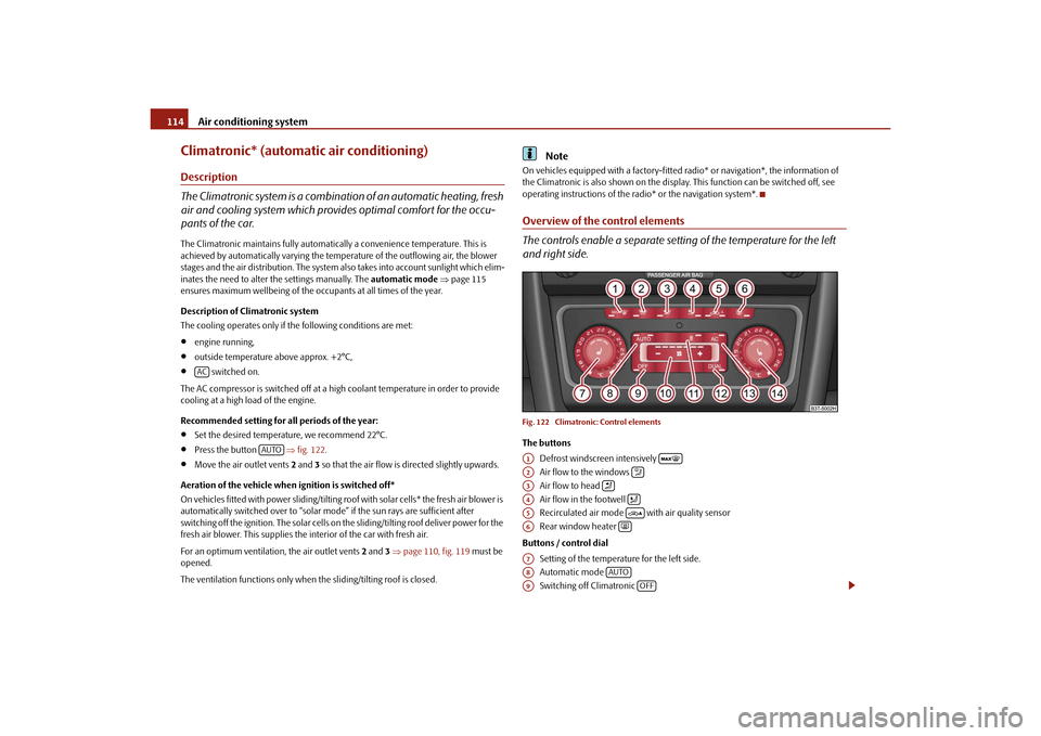
The controls enable a separate setting of the temperature for the left
and right side.Fig. 122 Climatronic: Control elementsThe buttons
Defrost windscreen intensively
Air flow to the windows
Air flow to head
Air flow in the footwell
Recirculated air mode with air quality sensor
Rear window heater
Buttons / control dial Setting of the temperature for the left side.
Automatic mode
Switching off Climatronic
AC
AUTO
A1
A2
A3
A4
A5
A6
A7A8
AUTO
A9
OFF
s3fg.2.book Page 114 Friday, April 30, 2010 12:17 PM
Page 116 of 287
Air conditioning system115
Using the system
Safety
Driving Tips
General Maintenance
Breakdown assistance
Technical Data
Setting the blower speed
Depending on the vehicle equipment: Butto
n for direct switching on/off of auxil-
iary heating* page 117, or switching on/off of windscreen heater*
Switching on/off of the temperature setting in dual mode
Switching cooling on and off
Setting of the temperature for the right side.
Note
Below the top row of buttons is located the interior temperature sensor. Do not glue
or cover over the sensor, otherwise it could have an unfavourable effect on the
Climatronic.Automatic mode
The automatic mode is used in order to maintain a constant tempera-
ture and to demist the windows in the interior of the car.Switching automatic mode on– Set a temperature between +18 °C and +26 °C.
– Move the air outlet vents 2 and 3 page 110, fig. 119 , so that the air flow is
directed slightly upwards.
– Press the button . In the right or left top corner a warning light lights up, depending on which unit was last selected.
If the warning light in the top right corner of the button lights up, the
Climatronic operates in “HIGH” mode. The “HIGH” mode is the standard setting of the
Climatronic.
When pressing again the button , the Climatronic changes into the “LOW” mode
and the warning light in the top left corner lights up. The Climatronic uses only in this
mode the lower blower speed. However taking into account the noise level, this is
more comfortable, yet be aware that the effectiveness of the air conditioning system is
reduced particularly if the vehicle is fully occupied.
By pressing again the button , you change into the “HIGH” mode. The automatic mode is switched off by pres
sing the button for the air distribution or
increasing or decreasing the blower speed. The temperature is nevertheless
regulated.
switching cooling on and offswitching cooling on and off– Press the button . The warning light lights up in the button.
– When you again press the switch , the cooling system is switched off. The warning light in the button goes out. Only the function of the ventilation remains
active when no lower temperature than the outside temperature can be reached.Setting temperatureYou can separate the interior temperature for the left and right side separately.
– You can set the temperature for both sides after switching on the ignition with the control dial .
– If you wish to set the temperature for the right side, turn the control dial . The warning light in the button lights up, this indicates that differing tempera-
tures for the left and right side can be set.
If the warning light in the button ligh ts up, the temperature for both sides
cannot be set with the control dial . You can reinitiate this function by pressing the
button . The warning light in the button which indicates the possibility to set
differing temperatures for the left and right side, goes out.
You can set the interior temperature between +18°C and +26°C. The interior temper-
ature is regulated automatically within this range. If you chose a temperature lower
than +18°C, a blue symbol lights up at the start of the numerical scale. If you chose a
temperature higher than +26°C, a red symbol lights up at the end of the numerical
scale. In both limit positions the Climatro nic operates at maximum cooling or heating
capacity, respectively. The temperatur e is not controlled in this case.
Lengthy and uneven distribution of the air flow out of the vents (in particular at the leg
area) and large differences in temperature, for example when getting out of the vehicle,
can result in chills in sensitive persons.
A10
A11
A12
DUAL
A13
AC
A14
AUTO
AUTO
AUTOAUTO
AC
AC
A7
A14
DUALDUALA7
DUAL
s3fg.2.book Page 115 Friday, April 30, 2010 12:17 PM