key SKODA SUPERB 2010 Owner´s Manual
[x] Cancel search | Manufacturer: SKODA, Model Year: 2010, Model line: SUPERB, Model: SKODA SUPERB 2010Pages: 252, PDF Size: 16.33 MB
Page 148 of 252
Only engage reverse gear when the vehicle is stationary. Depress the clutch
pedal and hold it fully depressed. Wait a moment before reverse gear is engag-
ed to avoid any shift noises.
The reversing lights will come on once reverse gear is engaged, provided the
ignition is on.WARNINGNever engage reverse gear when driving – risk of accident!
CAUTION
If not in the process of changing gear, do not leave your hand on the gearshift
lever while driving. The pressure from the hand can cause the gearshift mech-
anism to wear excessively.
Pedals
The operation of the pedals must not be hindered under any circumstances!
In the driver's footwell, only a footmat, which is attached to the two corre-
sponding attachment points, may be used.
Only use footmats from the range of ŠKODA Original Accessories, which are fit-
ted to two attachment points.
WARNINGNo objects are allowed in the driver's footwell – risk of obstruction or limi-
tation in operating the pedals!
Automatic transmission
Introduction
This chapter contains information on the following subjects:
Modes and use of selector lever
145
Manual gear shifting (Tiptronic)
146
Starting off and driving
147
Malfunction
148WARNING■ Do not depress the accelerator if the forward driving mode is changed
when the vehicle is halted and the engine is running – there is a risk of an
accident.■
Never shift the selector lever to R or P modes when driving – there is a
risk of an accident.
■
The vehicle must be held on the brake pedal in D, S or R modes if the ve-
hicle is halted and the engine is running. Even when the engine is idling,
power transmission is never completely interrupted – the vehicle will creep.
CAUTION
■ If the selector lever is shifted to N while the vehicle is being driven you must
lift off the accelerator pedal and you will need to wait until the engine has
reached its idling speed before shifting the selector lever to a forward driving
mode again.■
At temperatures below -10 °C, the engine can only be started in selector lev-
er position P.
■
Never try to hold the vehicle using the accelerator pedal when stopping on a
hill – this may lead to transmission damage.
Note
After the ignition is switched off, the ignition key can only be withdrawn when
the selector lever is in position P.
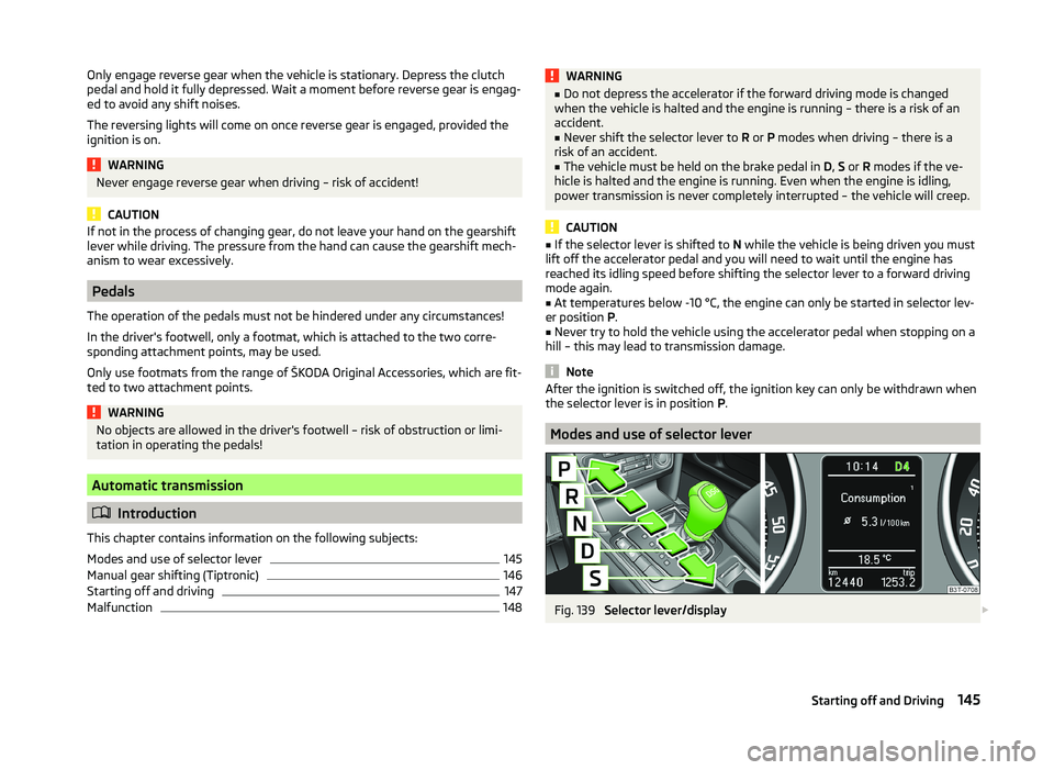
Modes and use of selector lever
Fig. 139
Selector lever/display
145Starting off and Driving
Page 163 of 252

›The system key is pressed.
› The ASR system is turned off.
› There is a driver intervention in the automatic steering operation (wheel
stop).
› When there is a system fault (system temporarily not available).
› There is an automatic emergency braking.
If any of the above events occurs, the following message is dis-
played » page 160 .
Departing from a parallel parking space
Read and observe
and on page 158 first.
Manoeuvring out
›
Press the symbol button once
» Fig. 149 on page 158 .
›
Activate the turn signal for side of the vehicle where the parking space is out
of which you wish to manoeuvre.
›
Select reverse gear or move the selector lever into position R.
›
As soon as the following message is shown in the display: Steering int. ac-
tive. Monitor area around veh.! , let go of the steering wheel. The steering
will be taken over by the system.
›
Observe the direct vicinity of the vehicle and reverse carefully.
›
Follow the system instructions shown in the display.
As soon as the parking procedure is completed, an audible signal sounds and
the following message appears in the information display:
Take over steering and continue driving
Automatic termination
The system terminates the manoeuvring procedure if one of the following ca-
ses arises.
› The system key is pressed.
› The ASR system is turned off.
› There is a driver intervention in the automatic steering operation (wheel
stop).
› When there is a system fault (system temporarily not available).
› There is an automatic emergency braking.
If any of the above events occurs, the following message is dis-
played » page 160 .
Automatic emergency braking
Read and observe
and on page 158 first.
If the system detects a risk of collision during parking, automatic emergency
braking takes place to prevent a collision.
The parking is terminated by the emergency braking.
CAUTION
If the parking is aborted due to the speed exceeding 7 km / h for the second
speed, then the automatic emergency braking is not triggered by the system!
Information messages
Read and observe
and on page 158 first.
Park Assist: Speed too high.
If a speed of 50 km / h is exceeded while searching for a parking space, the
system with the key symbol is must be reactivated.
Speed too high. Take over steering!
The parking is terminated if the speed exceeds 7 km / hr. Driver steering intervention: Take over steering!
The parking procedure is terminated due to a driver steering intervention. Park Assist stopped. ASR deactivated.
The parking procedure cannot be carried out because the ASR system is deac-
tivated. Activate the ASR.
ASR deactivated. Take over steering!
The parking procedure was ended because ASR was deactivated during the parking procedure.
Trailer: Park Assist stopped.
The parking procedure cannot be carried out because a trailer is hitched. Time limit exceeded. Take over steering!
The parking procedure was ended because the time limit of 6 minutes was
passed.
Park Assist currently not available.
160Driving
Page 169 of 252
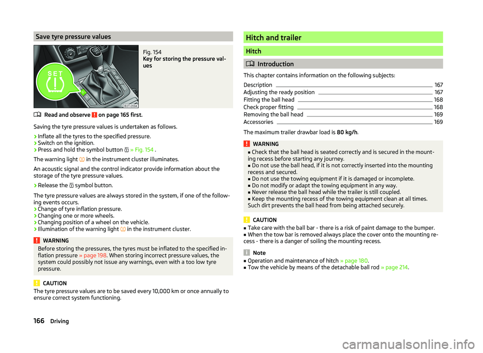
Save tyre pressure valuesFig. 154
Key for storing the pressure val-
ues
Read and observe on page 165 first.
Saving the tyre pressure values is undertaken as follows.
›
Inflate all the tyres to the specified pressure.
›
Switch on the ignition.
›
Press and hold the symbol button
» Fig. 154 .
The warning light in the instrument cluster illuminates.
An acoustic signal and the control indicator provide information about the
storage of the tyre pressure values.
›
Release the symbol button.
The tyre pressure values are always stored in the system, if one of the follow-
ing events occurs.
› Change of tyre inflation pressure.
› Changing one or more wheels.
› Changing position of a wheel on the vehicle.
› Illumination of the warning light
in the instrument cluster.
WARNINGBefore storing the pressures, the tyres must be inflated to the specified in-
flation pressure » page 198. When storing incorrect pressure values, the
system could possibly not issue any warnings, even with a too low tyre
pressure.
CAUTION
The tyre pressure values are to be saved every 10,000 km or once annually to
ensure correct system functioning.Hitch and trailer
Hitch
Introduction
This chapter contains information on the following subjects:
Description
167
Adjusting the ready position
167
Fitting the ball head
168
Check proper fitting
168
Removing the ball head
169
Accessories
169
The maximum trailer drawbar load is 80 kg/h.
WARNING■
Check that the ball head is seated correctly and is secured in the mount-
ing recess before starting any journey.■
Do not use the ball head, if it is not correctly inserted into the mounting
recess and secured.
■
Do not use the towing equipment if it is damaged or incomplete.
■
Do not modify or adapt the towing equipment in any way.
■
Never release the ball head while the trailer is still coupled.
■
Keep the mounting recess of the towing equipment clean at all times.
Such dirt prevents the ball head from being attached securely.
CAUTION
■ Take care with the ball bar - there is a risk of paint damage to the bumper.■When the tow bar is removed always place the cover onto the mounting re-
cess - there is a danger of soiling the mounting recess.
Note
■ Operation and maintenance of hitch » page 180.■Tow the vehicle by means of the detachable ball rod » page 214.166Driving
Page 170 of 252

DescriptionFig. 155
Carrier for the towing device / tow bar
Read and observe
and on page 166 first.
The ball head can be removed and is kept in the spare wheel well or in a com-
partment for the spare wheel in the luggage compartment.
Support for the towing device and tow bar » Fig. 155
13-pin power socket
Safety eyelet
Mounting recess
Cap
Dust cap
Ball head
Operating lever
Lock cap
Release pin
Key
locking ball
Note
If you lose the key, please get in touch with a specialist garage.1234567891011Adjusting the ready positionFig. 156
Setting the ready position/ready position
Read and observe
and on page 166 first.
The coupling ball bar must be set prior to installation in the standby position.
If this is not in the ready position, then this must be set to the standby posi-
tion as follows.
›
Grip the ball head below the protective cap
2
.
›
Remove the cap from the lock.
›
Insert the key into the lock, so that its green marking is pointing upwards.
›
Turn key
1
in direction of the arrow, so that the red marking is facing up-
wards » Fig. 156 .
›
Press the release pin
3
as far as the stop in the direction of the arrow and
at the same time push the lever
4
downwards as far as it will go in the di-
rection of the arrow.
The operating lever remains locked in this position.
CAUTION
In the ready position, the key cannot be removed nor turned to a different po-
sition.167Hitch and trailer
Page 171 of 252

Fitting the ball headFig. 157
Insert the ball head/lock the lock, and put the lock cover on
Read and observe
and on page 166 first.
›
Pull cap
4
» Fig. 155 on page 167 downwards.
›
Adjust the ball head to the ready position » page 167.
›
Grip the tow bar from underneath » Fig. 157 and insert into the mounting re-
cess until you hear it click into place » .
The operating lever
1
automatically turns upwards and the release pin
2
pops out (its red and green parts are visible) » .
If the operating lever
1
does not automatically emerge, or if the release pin
2
does not pop out, remove the ball head from the mounting recess by turn-
ing the lever downwards as far as it will go. Clean the tapered surfaces on the
ball head and the mounting recess.
›
Turn the key
3
180° to the right so that its green marker points upward.
›
Remove the key in the direction of the arrow.
›
Insert and press the cap
4
onto the lock in the direction of the arrow » .
›
Check the ball head for secure mounting » page 168.
WARNING■
Keep your hands outside the lever's range of motion when attaching the
ball head – there is a risk of fingers being injured!■
Never attempt to pull the operating lever upwards forcibly to turn the
key. Doing so would mean the ball head is not attached correctly.
CAUTION■ After removing the key, always replace the cover on the lock – there is a risk
of the lock getting dirty.■
Keep the mounting recess of the towing equipment clean at all times. Such
dirt prevents the ball head from being attached securely.
Check proper fitting
Fig. 158
Correctly secured ball head
Read and observe and on page 166 first.
Check that the ball head is fitted properly each time before use.
Correctly secured ball head » Fig. 158
Lever
1
is up as far as it will go » Fig. 158.
The release pin
2
is completely exposed (both its red and green parts are
visible).
The key is removed.
Cap
3
is on the lock.
The ball head does not come out of the mounting recess even after heavy
“shaking”.
WARNINGThe towing device can only be used when the tow bar is correctly locked –
there is the risk of an accident occurring.168Driving
Page 172 of 252

Removing the ball headFig. 159
Unlock the operating lever of the ball head/removing the ball
head
Read and observe
and on page 166 first.
›
Remove cover
1
» Fig. 159 from the lock in the direction of the arrow.
›
Insert the key into the lock, so that its green marking is pointing upwards.
›
Turn the key
2
180° to the left so that its red marker points upward.
›
Grasp the ball head from underneath.
›
Press the release pin
3
as far as the stop in the direction of the arrow and
at the same time push the lever
4
downwards as far as it will go in the di-
rection of the arrow.
The ball head is released in this position and falls freely into the hand. If it
does not fall freely into the hand, use your other hand to push it upwards.
At the same time, the ball head latches into the ready position and is thus
ready to be re-inserted into the mounting recess »
.
›
Place the cap
4
» Fig. 155 on page 167 onto the mounting recess.
WARNINGNever allow the ball head to remain unsecured in the boot. This could
cause damage to the boot upon sudden braking, and could put the safety
of the occupants at risk.CAUTION■ If the lever is held firmly and not pushed downwards as far as it can go, it will
go back up after the ball head is removed and will not latch into the ready po-
sition. The ball head then needs to be brought into this position before the
next time it is fitted.■
Tuck the ball bar in the ready position, with the golden key up, in the box -
otherwise there is a risk of damage to the key!
■
Do not use excessive force when handling the operating lever (e.g. do not
step on it).
Note
■ We recommend that you put the protective cap on the ball before removing
the ball head.■
Clean any dirt from the ball head before stowing it away in the box with the
vehicle tool kit.
Accessories
Fig. 160
Representation of the maximum
permissible level of the ball head
of the towing hitch and the per-
missible total weight of the ac-
cessories including the load de-
pending on the load center of
gravity
Read and observe and on page 166 first.
An accessory can mounted on the ball head of the towing hitch (e.g. bike carri-
ers).
If this accessory is used, the maximum permissible overhang of the ball head
of the towing hitch and the permissible gross vehicle weight of the accesso-
ries including load are to be checked.
The maximum permissible overhang of the ball head of the towing hitch is 70
cm » Fig. 160 .
The total permitted weight of the accessory including load changes with in-
creasing distance of the centre of gravity of the load from the ball head of the
towing hitch.
169Hitch and trailer
Page 175 of 252
Engine overheating
The speed must be reduced immediately if the needle for the coolant tempera-
ture gauge moves into the right-hand area or the red area of the scale.
Stop and switch off the engine if the warning light
in the instrument cluster
illuminates.
The following guidelines must be observed » page 36,
Coolant .
The coolant temperature can be reduced by switching on the heating.WARNING■ Always drive particularly carefully with the trailer.■Adapt your speed to the conditions of the road surface and to the traffic
situation.
CAUTION
If you tow a trailer frequently, you should also have your vehicle inspected be-
tween service intervals.
Trailer stabilisation (TSA)
The trailer stabilisation is an extension of the stabilisation control that works
in conjunction with the counter-steering assistance to reduce the amount the
trailer "sways".
After turning on the ignition, the ESC warning light
in the instrument cluster
illuminates for about 2 seconds longer than the ABS warning light.
Function requirements for trailer stabilisation. The trailer was shipped from the factory or purchased from the ŠKODA
genuine accessories.
The ESC is active. (Warning lights
or
do not illuminate in the instru-
ment cluster).
The trailer is electrically connected to the towing vehicle by means of the
trailer socket.
The speed is higher than approx. 60 km/h.
The trailer has a rigid drawbar.
WARNING■ The increased safety offered by the trailer stabilisation must not tempt
you to take greater risks than otherwise.■
Avoid abrupt and sudden driving and braking manoeuvres - there is a risk
of accidents.
CAUTION
■ The trailer stabilisation need not be able to correctly detect all of driving sit-
uations.■
Light trailers that sway are not always detected and therefore stabilised ac-
cordingly by the trailer stabilisation.
■
Release the pressure on the accelerator pedal if the system is being regula-
ted.
Note
The trailer stabilisation works for both braked and unbraked trailers.
Anti-theft alarm system
When the vehicle is locked, the alarm is activated when the electrical connec-
tion to the trailer is interrupted.
Always switch off the anti-theft alarm system before a trailer is coupled or un-
coupled » page 55 .
Conditions for including a trailer in the anti-theft alarm system. The vehicle is factory fitted with an anti-theft alarm system and towing
equipment.
The trailer is electrically connected to the towing vehicle by means of the
trailer socket.
The electrical system of the vehicle and trailer is functional.
The vehicle is locked with the vehicle key and the anti-theft alarm system
is activated.
CAUTION
For technical reasons, trailers with rear LED lights cannot be connected to the
anti-theft alarm system.172Driving
Page 189 of 252
CAUTION■Just filling the tank once with diesel fuel that does not comply with the
standard, can cause severe damage to parts of the engine, the fuel and ex-
haust system!■
If a different fuel other than diesel fuel, which complies to the above men-
tioned standards (e.g. petrol) is used, do not start the engine or switch on the
ignition! Engine parts could be significantly damaged!
■
Water which has collected in the fuel filter can cause engine faults.
CAUTION
■ The vehicle cannot be operated with biofuel RME, therefore this fuel must
not be filled in the tank and used for driving the vehicle. The use of biofuel
RME can cause considerable damage to parts of the engine or fuel system.■
Do not mix any fuel additives, so-called “flow improvers” (petrol and similar
agents), into the diesel. This can result in considerable damage to parts of the
engine or the exhaust system!
Engine compartment
Introduction
This chapter contains information on the following subjects:
Opening and closing the bonnet
187
Engine compartment overview
188
Radiator fan
188
Windscreen washer system
188WARNINGInjuries or scolding or risks of accident or fire may occur when working in
the engine compartment. For this reason, it is essential to comply with the
warning instructions outlined below and with the general applicable safety
rules. The engine compartment of your car is a hazardous area!WARNINGInstructions before beginning work in the engine compartment■Turn off the engine and withdraw the ignition key.■
Firmly apply the handbrake.
WARNING (Continued)■ If the vehicle is fitted with a manual gearbox, move the gearshift lever in-
to Neutral, or if the vehicle is fitted with an automatic gearbox, move the
selector lever into position P.■
Allow the engine to cool.
■
Never open the bonnet if you can see steam or coolant escaping from the
engine compartment – risk of scalding! Wait until no more steam or coolant
is escaping.
WARNINGInformation for working in the engine compartment■Keep all people, especially children, away from the engine compartment.■
Never touch the radiator fan while the engine is still warm. The fan might
suddenly start running!
■
Do not touch any hot engine parts – risk of burns!
■
The coolant is harmful to health.
■
Avoid contact with the coolant.
■
Coolant vapours are harmful to health.
■
Never open the end cover of the coolant expansion reservoir while the
engine is still warm. The cooling system is pressurized!
■
When opening the end cover of the coolant expansion reservoir, cover it
with a cloth to protect your face, hands and arms from hot steam or hot
coolant.
■
If any coolant splashes into your eyes, immediately rinse out your eyes
with clear water and contact a doctor as soon as possible.
■
Always keep the coolant in the original container, safe from people who
are not completely independent, especially children - there is a danger of
poisoning!
■
Consult a doctor immediately if coolant is swallowed.
■
Never spill fluids on the hot engine. Such fluids (e.g. the antifreeze con-
tained in the coolant) may ignite!
WARNINGInformation for working in the engine compartment with the engine run-
ning■
Pay particular attention to rotating engine parts (e.g. V-ribbed belt, gen-
erator, radiator fan) and the high voltage ignition system – risk to life!
■
Never touch the electric wiring on the ignition system.
186General Maintenance
Page 218 of 252
If the towing device is removed completely, it must be replaced with the
standard reinforcement of the rear bumper which is part of the mount for the
towing eye.
If this procedure is not observed, the vehicle may not meet the national legal
provisions.
CAUTION
The detachable ball rod and/or the vehicle can be damaged if an unsuitable
tow bar is used.
Note
The detachable ball rod must always be in the vehicle so that it can be used for
towing, if necessary.
Radio remote control
Introduction
This chapter contains information on the following subjects:
Replacing the battery in the remote control key
215
Synchronising the remote control
215
Replace the battery in the remote control of the auxiliary heater (parking
heater)
216
CAUTION
■ The replacement battery must have the same specification as the original
battery.■
We recommend having faulty batteries replaced by a ŠKODA service partner.
■
Pay attention to the correct polarity when changing the battery.
For the sake of the environment
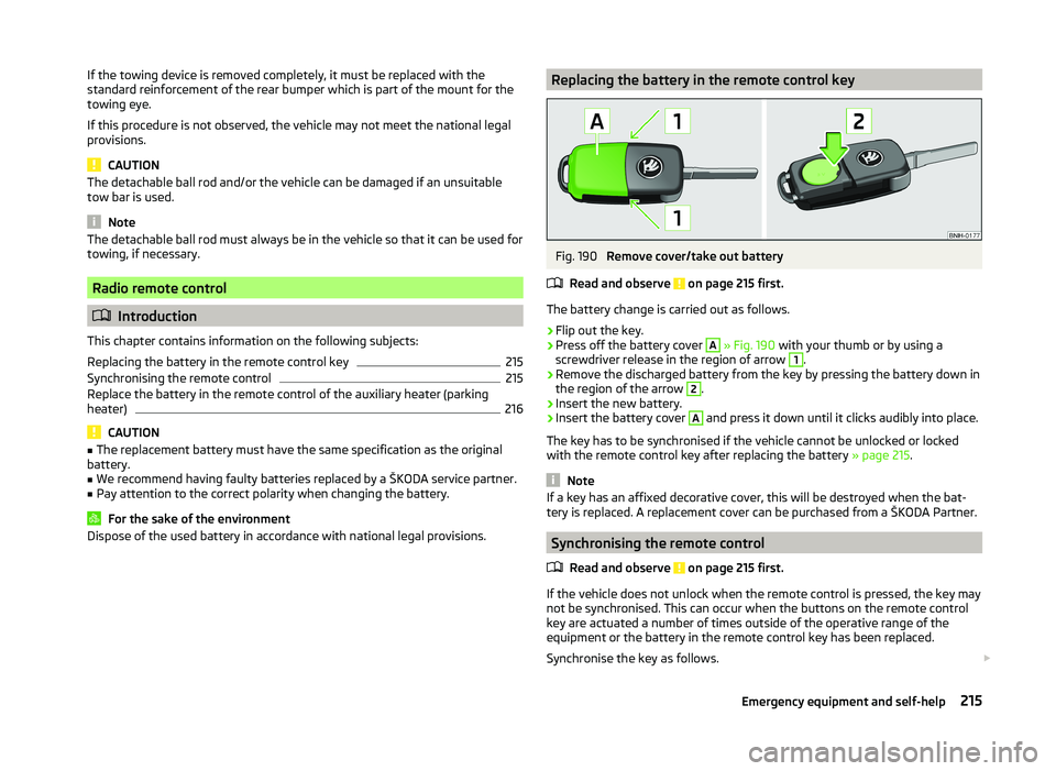
Dispose of the used battery in accordance with national legal provisions.Replacing the battery in the remote control keyFig. 190
Remove cover/take out battery
Read and observe
on page 215 first.
The battery change is carried out as follows.
›
Flip out the key.
›
Press off the battery cover
A
» Fig. 190 with your thumb or by using a
screwdriver release in the region of arrow
1
.
›
Remove the discharged battery from the key by pressing the battery down in
the region of the arrow
2
.
›
Insert the new battery.
›
Insert the battery cover
A
and press it down until it clicks audibly into place.
The key has to be synchronised if the vehicle cannot be unlocked or locked
with the remote control key after replacing the battery » page 215.
Note
If a key has an affixed decorative cover, this will be destroyed when the bat-
tery is replaced. A replacement cover can be purchased from a ŠKODA Partner.
Synchronising the remote control
Read and observe
on page 215 first.
If the vehicle does not unlock when the remote control is pressed, the key maynot be synchronised. This can occur when the buttons on the remote control
key are actuated a number of times outside of the operative range of the
equipment or the battery in the remote control key has been replaced.
Synchronise the key as follows.
215Emergency equipment and self-help
Page 219 of 252

›Press any button on the remote control key.›Unlock the door with the key in the lock cylinder within 1 minute of pressing
the button.
Replace the battery in the remote control of the auxiliary heater
(parking heater)
Fig. 191
Radio remote control: Battery
cover
Read and observe on page 215 first.
The battery is located under a cover on the back of the radio remote con-
trol » Fig. 191 .
›
Insert a flat, blunt object, such as a coin, into the gap of the battery cover.
›
Turn the cover against the direction of the arrow up to the mark to open the
cover.
›
Replace the battery.
›
Return the battery cover.
›
Turn the cover in the direction of the arrow up to the initial marking, engage.
Emergency unlocking/locking
Introduction
This chapter contains information on the following subjects:
Unlocking/locking the driver's door
216
Locking the door without a locking cylinder
217
Unlocking the boot lid
217
Selector lever-emergency unlocking
217Unlocking/locking the driver's doorFig. 192
Handle on the driver's door: cov-
ered key cylinder
The driver's door can be unlocked or locked in an emergency.
›
Pull on the door handle and hold it pulled.
›
Insert the vehicle key into the slot on the underside of the cover in the re-
gion of the arrow » Fig. 192.
›
Fold the cover upwards.
›
Release the door handle.
›
Insert the remote control key into the lock cylinder and unlock or lock the ve-
hicle.
›
For vehicles with LHD insert the remote control key with the buttons facing
up into the lock cylinder and unlock or lock the vehicle.
›
For vehicles with RHD insert the remote control key directed with buttons
down into the lock cylinder and unlock or lock the vehicle.
Pull on the door handle and install the cover to the original location.
CAUTION
Make sure you do not damage the paint when performing an emergency lock-
ing/unlocking.216Do-it-yourself