engine coolant SKODA SUPERB 2010 Owner´s Manual
[x] Cancel search | Manufacturer: SKODA, Model Year: 2010, Model line: SUPERB, Model: SKODA SUPERB 2010Pages: 252, PDF Size: 16.33 MB
Page 6 of 252
General Maintenance
Car care173
Services, modifications and technical
alterations
173
Washing vehicle
176
Taking care of your vehicle exterior
177
Taking care of the interior
181
Inspecting and replenishing
183
Fuel
183
Engine compartment
186
Engine oil
189
Coolant
191
Brake fluid
192
Vehicle battery
193
Wheels
197
Tyres and wheel rims
197
Manufacturer-approved tyre variants
201
Winter operation
203
Do-it-yourself
Emergency equipment and self-help
204
Emergency equipment
204
Changing a wheel
205
Puncture set
209
Jump-starting
211
Towing the vehicle
213
Radio remote control
215
Emergency unlocking/locking
216
Emergency operation of the sliding/tilting
roof
217
Replacing windscreen wiper blades
218
Fuses and light bulbs
220
Fuses
220
Replacing bulbs
223Technical data
Technical data228
Vehicle data
228
Index
3Table of Contents
Page 11 of 252
Safety
Passive Safety
General information
Introduction
This chapter contains information on the following subjects:
Before setting off
8
Driving safety
8
Safety equipment
8
In this section you will find important information, tips and notes on the sub-
ject of passive safety in your vehicle.
We have combined everything here which you should be familiar with, for ex-
ample, regarding seat belts, airbags, child seats and safety of children.
WARNING■ This chapter contains important information on how to use the vehicle for
the driver and his occupants.■
You can find further information on safety concerning you and those trav-
elling with you in the following chapters of this owner's manual.
■
The complete on-board literature should always be in the vehicle. This
applies in particular, if you rent out or sell the vehicle.
Before setting off
Read and observe
on page 8 first.
For your own safety and the safety of the people travelling with you, please
pay attention to the following points before setting off.
Ensure that the lighting and the turn signal system are functioning proper-
ly.
Ensure that the function of the wiper and the condition of the wiper
blades are free of any defects.
Ensure that all of the windows offer good visibility to the outside.
Adjust the rear-view mirror so that vision to the rear is guaranteed.
Ensure that the mirrors are not covered.
Check the tyre inflation pressure.
Check the engine oil, brake fluid and coolant level.
Secure all items of luggage.
Do not exceed the permissible axle loads and permissible gross weight of
the vehicle.
Close all doors as well as the bonnet and boot lid.
Ensure that no objects can obstruct the pedals.
Protect children in suitable child seats with correctly fastened seat
belts » page 22 , Transporting children safely .
Adopt the correct seated position » page 9, Correct and safe seated
position . Tell your passengers to assume the correct seated position.
Driving safety
Read and observe
on page 8 first.
The driver is fully responsible for himself and his occupants. If your driving
safety is affected, you place yourself and the oncoming traffic at risk.
The following guidelines must therefore be observed. Do not become distracted from concentrating on the traffic situation, e.g.
by your passengers or mobile phone calls.
Never drive when your driving ability is impaired, e.g. due to medication, al-
cohol or drugs.
Keep to the traffic regulations and the permissible speed limit.
Always adjust the driving speed to the road, traffic and weather condi-
tions.
Take regular breaks on long journeys – at least every two hours.
Safety equipment
Read and observe
on page 8 first.
The following list contains only part of the safety equipment in your vehicle.
› Three-point seat belts for all the seats.
› Belt force limiter for front and outer rear seats.
› Belt tensioner for front and outer rear seats.
› Seat belt height adjusters for the front seats.
› Front airbag for the driver and the front passenger.
› Driver’s knee airbag.
8Safety
Page 33 of 252
Instruments and Indicator Lights
Instrument cluster
Introduction
This chapter contains information on the following subjects:
Overview
30
Revolution counter
31
Speedometer
31
Coolant temperature gauge
31
Display
31
Fuel gauge
32
Counter for distance driven
32
32
Display of the second speed
33
Display in rear centre console
33
Auto Check Control
33
Fault display
The Error message will appear in the display if there is a fault in the instru-
ment cluster. Ensure that the fault is rectified as soon as possible by a special-
ist workshop.
WARNING■ Concentrate fully at all times on your driving! As the driver you are fully
responsible for road safety.■
Never operate the controls in the instrument cluster while driving - risk of
accident. Operate the controls only when the vehicle is at a standstill.
OverviewFig. 21
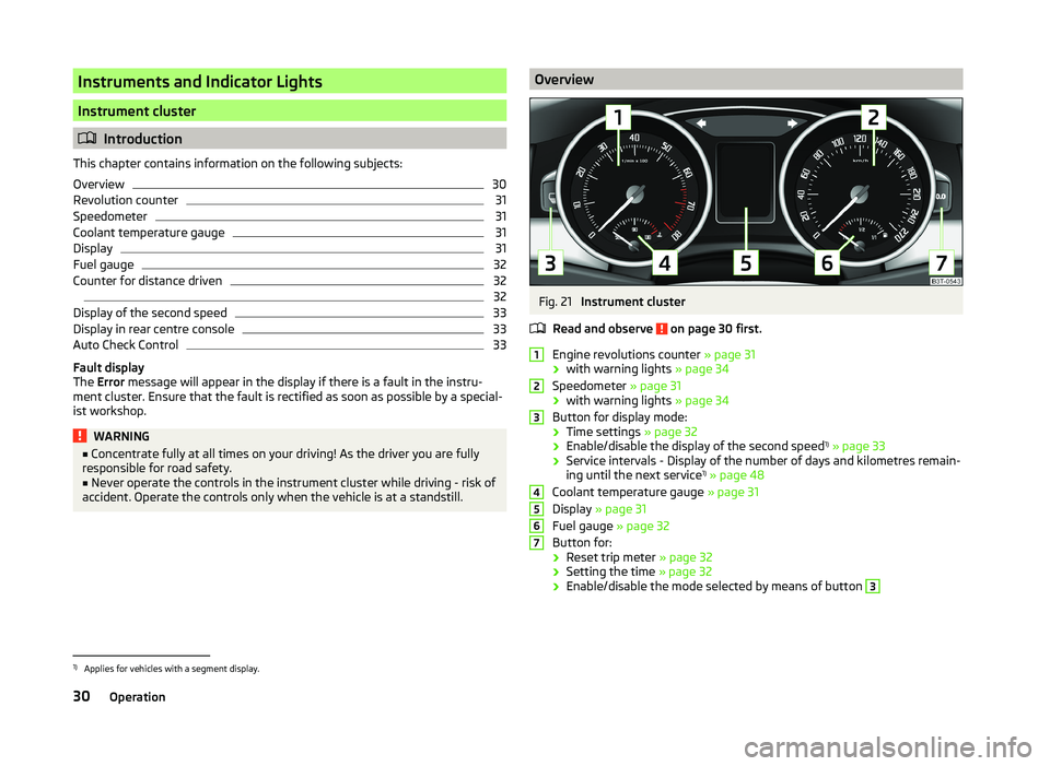
Instrument cluster
Read and observe
on page 30 first.
Engine revolutions counter » page 31
› with warning lights
» page 34
Speedometer » page 31
› with warning lights
» page 34
Button for display mode:
› Time settings
» page 32
› Enable/disable the display of the second speed 1)
» page 33
› Service intervals - Display of the number of days and kilometres remain-
ing until the next service 1)
» page 48
Coolant temperature gauge » page 31
Display » page 31
Fuel gauge » page 32
Button for: › Reset trip meter
» page 32
› Setting the time
» page 32
› Enable/disable the mode selected by means of button
312345671)
Applies for vehicles with a segment display.
30Operation
Page 34 of 252
Revolution counterRead and observe
on page 30 first.
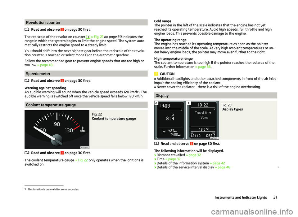
The red scale of the revolution counter
1
» Fig. 21 on page 30 indicates the
range in which the system begins to limit the engine speed. The system auto-
matically restricts the engine speed to a steady limit.
You should shift into the next highest gear before the red scale of the revolu-
tion counter is reached or select mode D on the automatic gearbox.
Follow the recommended gear to prevent engine speeds that are too high or
too low » page 43 .
Speedometer
Read and observe
on page 30 first.
Warning against speeding
An audible warning will sound when the vehicle speed exceeds 120 km/h 1)
. The
audible warning is switched off once the vehicle speed falls below 120 km/h.
Coolant temperature gauge
Fig. 22
Coolant temperature gauge
Read and observe on page 30 first.
The coolant temperature gauge » Fig. 22 only operates when the ignitions is
switched on.
Cold range
The pointer in the left of the scale indicates that the engine has not yet
reached its operating temperature. Avoid high speeds, full throttle and high
engine loads. This prevents possible damage to the engine.
The operating range
The engine has reached its operating temperature as soon as the pointer
moves into the middle of the scale. At very high ambient temperatures or un-
der heavy engine loads, the pointer may move even further to the right.
High temperature range
The coolant temperature is too high if the pointer reaches the red area of the
scale. Further information » page 36.
CAUTION
■
Additional headlights and other attached components in front of the air inlet
impair the cooling efficiency of the coolant.■
Never cover the radiator - there is a risk of the engine overheating.
Display
Fig. 23
Display types
Read and observe on page 30 first.
The following information will be displayed.
› Distance travelled
» page 32
› Time
» page 32
› Details of the information system
» page 42
› Details of the service interval display
» page 48
1)
This function is only valid for some countries.
31Instruments and Indicator Lights
Page 37 of 252
The following message is shown in the MAXI DOT display.Gearbox overheated. Stop! Owner's manual!
do not continue to drive! Stop the vehicle, switch off the engine, and wait
until the
icon goes out – risk of gearbox damage! You can continue your
journey as soon as the icon disappears.WARNINGIf you have to stop for technical reasons, then park the vehicle at a safe
distance from the traffic, switch off the engine and activate the hazard
warning light system » page 72. The warning triangle must be set up at
the prescribed distance - observe the national legal provisions when doing
so.
Note
■ If the MAXI DOT display shows warning messages, these messages must be
confirmed in order to access the main menu » page 42 .■
As long as the operational faults are not rectified, the symbols are always in-
dicated again. After they are displayed for the first time, the symbols continue
to be indicated without any extra messages for the driver.
Warning lights
Introduction
This chapter contains information on the following subjects:
Handbrake
35
Brake system
35
Seat belt warning light
35
Generator
35
Door open
36
Engine oil pressure
36
Coolant
36
Bonnet
36
Boot lid
36
Power steering / steering lock (system KESSY)
36
Engine oil level
37
Traction Control System (ASR)
37
Electronic Stability Control (ESC)
37 Anti lock brake system (ABS)38 Rear fog light38
Lamp failure
38
Adaptive headlights (AHL)
38
Exhaust inspection system
38
Glow plug system (diesel engine)
38
Engine performance check (petrol engine)
39
Diesel particulate filter (diesel engine)
39
Fuel reserve
39
Airbag system
40
Tyre inflation pressure
40
Windscreen washer fluid level
40
Brake linings
41
Turn signal system
41
Low beam
41
Fog lights
41
Cruise control system
41
Selector lever lock / starter (system KESSY)
41
Main beam
41
The warning lights indicate certain functions or faults.
Some warning lights can be accompanied by acoustic signals and messages in
the display of the instrument cluster.
After switching on the ignition, some warning lights light up briefly as a func-
tion test.
If the tested systems are OK, the corresponding warning lights go out a few
seconds after switching on the ignition or after starting the engine.
34Operation
Page 38 of 252
WARNING■Ignoring illuminated warning lights and related messages or instructions
in the instrument cluster display may lead to serious personal injury or
damage to the vehicle.■
If you have to stop for technical reasons, then park the vehicle at a safe
distance from the traffic, switch off the engine and activate the hazard
warning light system » page 72. The warning triangle must be set up at
the prescribed distance - observe the national legal provisions when doing
so.
■
The engine compartment of your car is a hazardous area. The following
warning instructions must be followed at all times when working in the en-
gine compartment » page 186, Engine compartment .
Handbrake
Read and observe
on page 35 first.
The warning light
illuminates if the handbrake is applied.
An acoustic signal will sound if you drive the vehicle above 6 km/h for at least
3 seconds while the handbrake is applied.
The following message is shown in the MAXI DOT display. Release parking brake!
Brake system
Read and observe
on page 35 first.
The warning light
illuminates if the brake fluid level in the braking system is
too low or there is a fault in the ABS.
The following message is shown in the MAXI DOT display. Brake fluid: Owner's manual!
›
Stop the vehicle, switch off the engine, and check the level of the brake flu-
id » page 193 » .
WARNING■
If the warning light together with the warning light » page 38 ,
Anti lock brake system (ABS) illuminates, do not continue to drive! Seek
help from a specialist garage.■
A fault to the ABS system or the braking system can increase the vehi-
cle's braking distance – there is a risk of accident.
■
The following guidelines should be observed when opening the bonnet
and checking the brake fluid level » page 186, Engine compartment .
Seat belt warning light
Read and observe
on page 35 first.
The warning light
is illuminated as a reminder for the driver and front pas-
senger to fasten their seat belts.
The warning light
goes out , after the respective seat belt has been fas-
tened.
If the driver or front passenger has not fastened their seat belt and the vehicle
speed is more than 20 km/h, the warning light
flashes and you will hear an
acoustic warning signal.
The warning signal is switched off and the warning light
remains perma-
nently illuminated if the driver and front passenger have not fastened their
seat belts within the next 90 seconds.
Generator
Read and observe
on page 35 first.
If the warning light
is illuminated , when the engine is running, the vehicle
battery is not being charged.
Seek assistance from a specialist garage immediately. The electrical system re-
quires checking.
CAUTION
Do not continue driving if the warning light (coolant system fault) illumi-
nates in addition to the warning light while you are driving. Stop the engine
- there is a risk of engine damage. Seek help from a specialist garage.35Instruments and Indicator Lights
Page 39 of 252
Door openRead and observe
on page 35 first.
The warning light
illuminates if one or several doors are opened.
Engine oil pressure
Read and observe
on page 35 first.
When the warning light is flashing
, the engine oil pressure is too low.
The following message is shown in the MAXI DOT display. Oil pressure: Engine off. Owner's manual!
›
Stop the vehicle, switch off the engine, and check the engine oil lev-
el » page 190 .
If the warning light
flashes do not drive any further , even if the oil level is
correct! Also do not leave the engine running at an idling speed.
Seek help from a specialist garage.
Coolant
Read and observe
on page 35 first.
If the warning light
illuminates or flashes , either the coolant temperature is
too high or the coolant level is too low.
The following message is shown in the MAXI DOT display. Check coolant! Owner's manual!
›
Stop the vehicle, switch off the engine and check the coolant lev-
el » page 192 .
›
If the coolant level is too low, top up coolant » page 192.
If the warning light
does not illuminate , after adding coolant and switching
on the ignition, you may continue your journey.
If the coolant level is within the specified range and the warning light is still
illuminated , then there may be a malfunction of the cooling fan.
›
Check the fuse for the radiator fan, replace if necessary » page 222, Fuses in
the engine compartment .
If the coolant level and fan fuse are both OK but the warning light is never-
theless still illuminated, do not continue your journey!
Seek help from a specialist garage.WARNING■ Carefully open the coolant expansion bottle. If the engine is hot, the cool-
ing system is pressurized - risk of scalding! It is therefore best to allow the
engine to cool down before removing the cap.■
Do not touch the radiator fan. The radiator fan may switch itself on auto-
matically even if the ignition is off - a danger of injury is present!
CAUTION
■ Additional headlights and other attached components in front of the air inlet
impair the cooling efficiency of the coolant.■
Never cover the radiator - there is a risk of the engine overheating.
Bonnet
Read and observe
on page 35 first.
The warning light
illuminates if the bonnet is unlocked.
Boot lid
Read and observe
on page 35 first.
The warning light
illuminates if the boot lid is opened.
Power steering / steering lock (system KESSY)
Read and observe
on page 35 first.
Power steering
If the warning light
is illuminated , this indicates a partial failure of the Pow-
er Steering and the steering forces can be greater.
If the warning light
is illuminated , this indicates a complete failure of the
power steering and the steering assist has failed (significantly higher steering
forces).
›
Stop the car, turn the ignition off and on again.
The powered steering is fully functional again if the
or
warning light does
not illuminate after you switch the engine back on.
36Operation
Page 113 of 252

Air conditioning system
Heating, ventilation, cooling
Introduction
This chapter contains information on the following subjects:
Air outlets
110
Using the air conditioning system economically
111
Operational problems
112
The heating effect is dependent upon the coolant temperature, thus full heat
output only occurs when the engine has reached its operating temperature.
If the cooling system is switched on, the temperature and air humidity drops in
the vehicle. The cooling system prevents the windows from misting up during
winter months.
It is possible to briefly activate recirculated air mode to enhance the cooling
effect.
Please refer to the information regarding recirculated air mode for the air con-
ditioning system » page 114 or for Climatronic » page 117.
WARNING■
For your own safety and that of other road users, ensure that all the win-
dows are free of ice, snow and misting. Please familiarize yourself about
how to correctly operate the heating and ventilation systems, how to de-
mist and defrost the windows, as well as with the cooling mode.■
To reduce health risks (e.g. common colds), the following instructions for
the use of the cooling system are to be observed. ■The difference between the indoor temperature and the outdoor air
temperature should not be greater than about 5 ° C.
■ The cooling system is to be turned off about 10 minutes before the end
of the journey.
■ Once a year, a disinfection of the air conditioner or the Climatronic is to
be carried out by a specialist company.
CAUTION■ The air inlet in front of the windscreen must be free (e.g. of ice, snow or
leaves) to ensure that the heating and cooling system operates properly.■
After switching on the cooling Condensation from the evaporator of the air
conditioning may drip down and form a puddle below the vehicle. This is not a
leak.
Note
■ The exhaust air streams out through vents at the rear of the luggage com-
partment.■
We recommend that you do not smoke in the vehicle when the recirculating
air mode is operating since the smoke which is drawn at the evaporator from
the interior of the vehicle forms deposits in the evaporator of the air condition-
ing system. This produces a permanent odour when the air conditioning sys-
tem is operating which can only be eliminated through considerable effort and
expense (replacement of compressor).
Air outlets
Fig. 123
Air vents at the front
110Operation
Page 115 of 252

Operational problemsRead and observe
and on page 110 first.
If the cooling system does not operate at outside temperatures higher than +5°C, there is a problem in the system. The reasons for this may be.
› One of the fuses has blown. Check the fuse and replace if necessa-
ry » page 220 .
› The cooling system has switched off automatically for a short time because
the coolant temperature of the engine is too hot » page 31.
If you are not able to resolve the operational problem yourself, or if the cooler
output has reduced, switch off the cooling system and seek assistance from a
specialist garage.
Air conditioning system (manual air conditioning system)
Introduction
This chapter contains information on the following subjects:
Control elements
112
adjusting
114
Recirculated air mode
114
The cooling system operates only if the following conditions are met. The cooling system is switched on » page 112.
The engine is running.
The outside temperature is above approximately +2 °C.
The blower is switched on.
Under certain circumstances, air at a temperature of about 5 °C can flow out of
the vents when the cooling system is switched on.
If the desired interior temperature can also be achieved without activating the
cooling system, fresh air mode should be selected.
The cooling system is switched off at a high coolant temperature in order to
provide cooling at a high load of the engine.
CAUTION
Lengthy and uneven distribution of the air flow out of the vents (especially
around the feet) and large differences in temperature, for example, when get-
ting out of the vehicle, can cause susceptible individuals to catch a cold.Note■ We recommend that you have the air conditioning system cleaned by a spe-
cialist garage once every year.■
During operation of the air conditioning, an increase in engine idle speed may
occur under certain circumstances in order to ensure sufficient heating com-
fort.
Control elements
Fig. 125
The air conditioning system: Control elements
Read and observe
on page 112 first.
Functions of the individual controls » Fig. 125 :
Set the temperature (turn to the left: to reduce the temperature, turn to
the right: to increase the temperature)
Set the blower level (level 0: blowers off, level 4: the highest blower
speed)
Set the direction of the air outlet » page 110
Switch the cooling system on/off
Switching the rear window heater on/off » page 75
Aux. heating on/off » page 118
Switch recirculation on/off » page 114
Control the seat heater on the front left seat » page 85
Control the seat heater on the front right seat » page 85
ABC112Operation
Page 118 of 252
Climatronic (automatic air conditioning system)
Introduction
This chapter contains information on the following subjects:
Control elements
115
automatic mode
116
Switching the cooling system on/off
116
Setting the temperature
116
Recirculation mode - Version 1
117
Recirculation mode - Version 2
117
Controlling blower
118
Defrosting windscreen
118
The Climatronic in automatic mode ensures the best possible setting for the
temperature of the air flowing out, the blower stage and air distribution.
The system also takes sunlight into account, which eliminates the need to al-
ter the settings manually.
The cooling system operates only if the following conditions are met. The cooling system is switched on » page 112.
The engine is running.
The outside temperature is above approximately +2 °C.
The blower is switched on.
The cooling system is switched off at a high coolant temperature in order to
provide cooling at a high load of the engine.
Aeration of the vehicle when ignition is switched off
On models fitted with power sliding/tilting roof with solar cells, the fresh air
blower is automatically switched over to “solar mode” if the sun rays are suffi- cient after switching off the ignition. The solar cells on the sliding/tilting roof
deliver power for the fresh air blower. This supplies the interior of the car with
fresh air.
For an optimum ventilation, the air outlet vents 2 and 3 must be
opened » Fig. 123 on page 110 .
The ventilation functions only when the sliding/tilting roof is fully closed.
Note■ We recommend that you have Climatronic cleaned by a specialist garage
once every year.■
During operation of the Climatronic, an increase in engine idle speed can oc-
cur under certain circumstances in order to ensure adequate heating comfort.
■
On vehicles equipped with a factory fitted radio or radio navigation system,
the Climatronic information is also shown on their displays. This function can
be switched off, see » operating instructions for the radio or navigation sys-
tem .
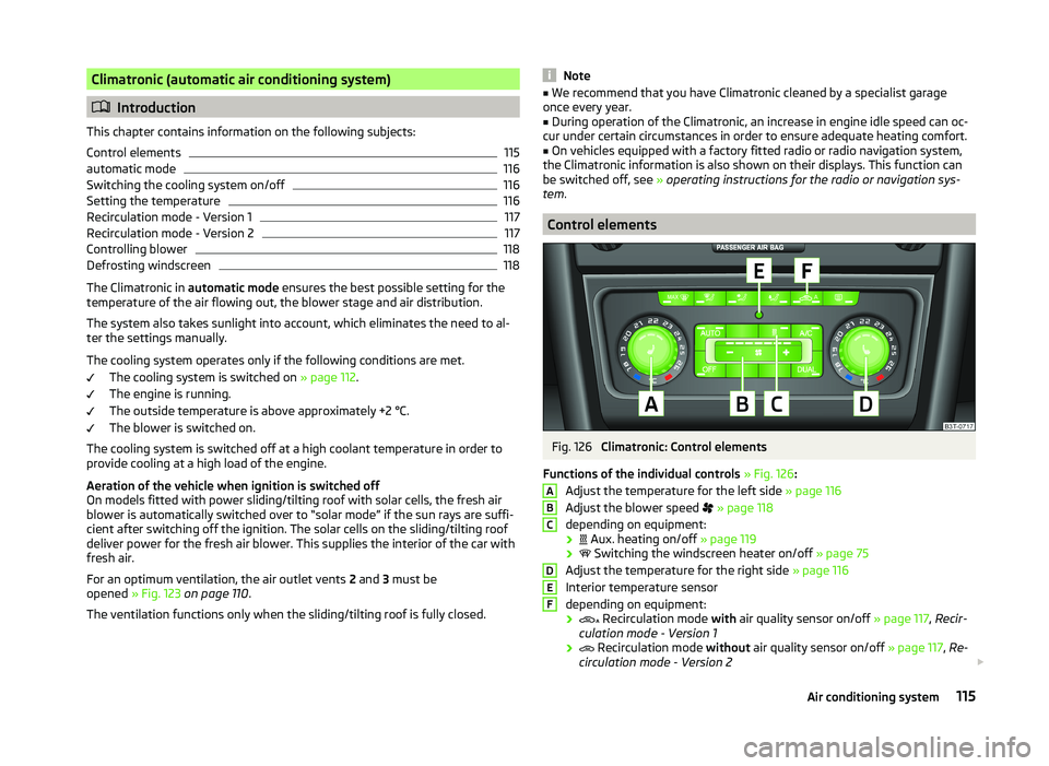
Control elements
Fig. 126
Climatronic: Control elements
Functions of the individual controls » Fig. 126 :
Adjust the temperature for the left side » page 116
Adjust the blower speed
» page 118
depending on equipment:
›
Aux. heating on/off
» page 119
›
Switching the windscreen heater on/off
» page 75
Adjust the temperature for the right side » page 116
Interior temperature sensor
depending on equipment:
›
Recirculation mode
with air quality sensor on/off » page 117, Recir-
culation mode - Version 1
›
Recirculation mode
without air quality sensor on/off » page 117, Re-
circulation mode - Version 2
ABCDEF115Air conditioning system