engine coolant SKODA SUPERB 2010 Owner´s Manual
[x] Cancel search | Manufacturer: SKODA, Model Year: 2010, Model line: SUPERB, Model: SKODA SUPERB 2010Pages: 252, PDF Size: 16.33 MB
Page 121 of 252

NoteAs soon as the windscreen mists up, press the symbol button . Press the
button once the windscreen has demisted.
Controlling blower
The Climatronic system controls the blower stages automatically in line with
the interior temperature.
However, the blower stages can be manually adapted to suit your particular
needs.
›
Repeatedly pressing the symbol button on the left or right reduces or in-
creases blower speed.
If the blower is switched off, the Climatronic system is switched off.
The set blower speed is displayed above the symbol button when the re-
spective number of warning lights illuminate.
WARNING■ “Stale air” may result in fatigue in the driver and occupants, reduce atten-
tion levels and also cause the windows to mist up. The risk of having an ac-
cident increases.■
Do not switch off the Climatronic system for longer than necessary.
■
Switch on the Climatronic system as soon as the windows mist up.
Defrosting windscreen
Switching on
›
Press the
button » Fig. 126 on page 115 .
›
Press the
button » Fig. 126 on page 115 .
Switching off
›
Press the symbol button
again or press the symbol button
.
›
Press the
button again.
More air flows out of the air outlet vents 1 » Fig. 123 on page 110 . The tempera-
ture control is controlled automatically.
Auxiliary heating (auxiliary heating and ventilation)
Introduction
This chapter contains information on the following subjects:
Switching on/off
119
Radio remote control
120
Functional requirements of the auxiliary heating (auxiliary heating and ventila-
tion)
The charge state of the vehicle battery is sufficient.
The fuel supply is adequate (the warning icon is not lit in the display of
the instrument cluster).
Auxiliary ventilation
The auxiliary ventilation enables fresh air to flow into the vehicle interior by
switching off the engine, whereby the interior temperature is effectively de-
creased (e.g. with the vehicle parked in the sun).
Additional heating (hereinafter only as a aux. heating)
The auxiliary heating can be used when both when stationary, when the en-
gine is switched off, to preheat the vehicle and also while driving (e.g. during
the heating phase of the engine).
The aux. heating functions in connection with the air conditioning system or
Climatronic.
The auxiliary heating also warms up the engine. This is not valid for vehicles
with the 3.6 l/191 kW FSI engine.
The auxiliary heating warms up the coolant by combusting fuel from the vehi-
cle tank. This warms the air flowing into the passenger compartment (if the
blower is turned on).
Depending on the environmental conditions, the automatic on or off of the
heater occurs, which causes the best possible conditions for the engine run-
ning and the interior heating.
For vehicles with petrol engines, the automatic switching on and off of the
heater can be disabled at a specialist workshop.
118Operation
Page 122 of 252

WARNING■The auxiliary heating must never be operated in closed rooms (e.g. garag-
es) – risk of poisoning!■
The auxiliary heating must not be allowed to run during refuelling – risk
of fire.
■
The exhaust pipe of the auxiliary heating is located on the underside of
the vehicle. If you want to use the heater, then the car should not be
parked in places where the exhaust gases can come into contact with flam- mable materials such as dry grass, undergrowth, leaves, spilled fuel or simi-
lar - Risk of fire.
CAUTION
■ The running auxiliary heater consumes fuel from the vehicle tank and auto-
matically controls the filling level. If only a low quantity of fuel is present in the
fuel tank, the auxiliary heating switches off.■
The exhaust pipe of the auxiliary heating, which is located on the underside
of the vehicle, must not be clogged and the exhaust flow must not be blocked.
■
If the auxiliary heating is running, the vehicle battery discharges. If the auxili-
ary heating and ventilation has been operated several times over a longer peri-
od, the vehicle must be driven a few kilometres in order to recharge the vehi-
cle battery.
■
The air inlet in front of the windscreen must be free (e.g. of ice, snow or
leaves) to ensure that the auxiliary heating operates properly.
Note
■ The auxiliary heating switches on the blower B » Fig. 125 on page 112
or » Fig. 126 on page 115 only if it has achieved a coolant temperature of ap-
prox. 50 °C.■
At low outside temperatures, this can result in a formation of water vapour in
the area of the engine compartment. This is quite normal and is not an operat-
ing problem.
■
So that warm air can flow into the vehicle interior after switching on the aux-
iliary heating, you must maintain the comfort temperature normally selected
by you, leave the fan switched on and leave the air outlet vents in an open po-
sition. It is recommended to put the air flow in the position
or
.
Switching on/offFig. 127
Button for switching on/off the system directly on the operating
part of the air conditioning/Climatronic
Read and observe
and on page 119 first.
The auxiliary heating can be switched on/off as follows.
Manually switching on using the button on the operating part of the manual air conditioning/Cli-
matronic. The warning light in the button illuminates » Fig. 127.
by using the radio remote control » page 120.
Manually switching off using the button on the operating part of the manual air conditioning/Cli-
matronic. The warning light in the button goes out » Fig. 127,
by using the radio remote control » page 120.
After switching off the auxiliary heating, the coolant pump still runs for a short period.
Automatic switching on/off
The following menu items can be selected from the Aux. heating menu item in
the information display » page 47 (depending on the vehicle equipment):
■ Day of the week - set the current day of the week;
■ Running time - Set the required running time in 5 minute increments. The
running time can be 10 to 60 minutes.
■ Mode - Set the desired heating/ventilation mode;
119Air conditioning system
Page 175 of 252
Engine overheating
The speed must be reduced immediately if the needle for the coolant tempera-
ture gauge moves into the right-hand area or the red area of the scale.
Stop and switch off the engine if the warning light
in the instrument cluster
illuminates.
The following guidelines must be observed » page 36,
Coolant .
The coolant temperature can be reduced by switching on the heating.WARNING■ Always drive particularly carefully with the trailer.■Adapt your speed to the conditions of the road surface and to the traffic
situation.
CAUTION
If you tow a trailer frequently, you should also have your vehicle inspected be-
tween service intervals.
Trailer stabilisation (TSA)
The trailer stabilisation is an extension of the stabilisation control that works
in conjunction with the counter-steering assistance to reduce the amount the
trailer "sways".
After turning on the ignition, the ESC warning light
in the instrument cluster
illuminates for about 2 seconds longer than the ABS warning light.
Function requirements for trailer stabilisation. The trailer was shipped from the factory or purchased from the ŠKODA
genuine accessories.
The ESC is active. (Warning lights
or
do not illuminate in the instru-
ment cluster).
The trailer is electrically connected to the towing vehicle by means of the
trailer socket.
The speed is higher than approx. 60 km/h.
The trailer has a rigid drawbar.
WARNING■ The increased safety offered by the trailer stabilisation must not tempt
you to take greater risks than otherwise.■
Avoid abrupt and sudden driving and braking manoeuvres - there is a risk
of accidents.
CAUTION
■ The trailer stabilisation need not be able to correctly detect all of driving sit-
uations.■
Light trailers that sway are not always detected and therefore stabilised ac-
cordingly by the trailer stabilisation.
■
Release the pressure on the accelerator pedal if the system is being regula-
ted.
Note
The trailer stabilisation works for both braked and unbraked trailers.
Anti-theft alarm system
When the vehicle is locked, the alarm is activated when the electrical connec-
tion to the trailer is interrupted.
Always switch off the anti-theft alarm system before a trailer is coupled or un-
coupled » page 55 .
Conditions for including a trailer in the anti-theft alarm system. The vehicle is factory fitted with an anti-theft alarm system and towing
equipment.
The trailer is electrically connected to the towing vehicle by means of the
trailer socket.
The electrical system of the vehicle and trailer is functional.
The vehicle is locked with the vehicle key and the anti-theft alarm system
is activated.
CAUTION
For technical reasons, trailers with rear LED lights cannot be connected to the
anti-theft alarm system.172Driving
Page 189 of 252
CAUTION■Just filling the tank once with diesel fuel that does not comply with the
standard, can cause severe damage to parts of the engine, the fuel and ex-
haust system!■
If a different fuel other than diesel fuel, which complies to the above men-
tioned standards (e.g. petrol) is used, do not start the engine or switch on the
ignition! Engine parts could be significantly damaged!
■
Water which has collected in the fuel filter can cause engine faults.
CAUTION
■ The vehicle cannot be operated with biofuel RME, therefore this fuel must
not be filled in the tank and used for driving the vehicle. The use of biofuel
RME can cause considerable damage to parts of the engine or fuel system.■
Do not mix any fuel additives, so-called “flow improvers” (petrol and similar
agents), into the diesel. This can result in considerable damage to parts of the
engine or the exhaust system!
Engine compartment
Introduction
This chapter contains information on the following subjects:
Opening and closing the bonnet
187
Engine compartment overview
188
Radiator fan
188
Windscreen washer system
188WARNINGInjuries or scolding or risks of accident or fire may occur when working in
the engine compartment. For this reason, it is essential to comply with the
warning instructions outlined below and with the general applicable safety
rules. The engine compartment of your car is a hazardous area!WARNINGInstructions before beginning work in the engine compartment■Turn off the engine and withdraw the ignition key.■
Firmly apply the handbrake.
WARNING (Continued)■ If the vehicle is fitted with a manual gearbox, move the gearshift lever in-
to Neutral, or if the vehicle is fitted with an automatic gearbox, move the
selector lever into position P.■
Allow the engine to cool.
■
Never open the bonnet if you can see steam or coolant escaping from the
engine compartment – risk of scalding! Wait until no more steam or coolant
is escaping.
WARNINGInformation for working in the engine compartment■Keep all people, especially children, away from the engine compartment.■
Never touch the radiator fan while the engine is still warm. The fan might
suddenly start running!
■
Do not touch any hot engine parts – risk of burns!
■
The coolant is harmful to health.
■
Avoid contact with the coolant.
■
Coolant vapours are harmful to health.
■
Never open the end cover of the coolant expansion reservoir while the
engine is still warm. The cooling system is pressurized!
■
When opening the end cover of the coolant expansion reservoir, cover it
with a cloth to protect your face, hands and arms from hot steam or hot
coolant.
■
If any coolant splashes into your eyes, immediately rinse out your eyes
with clear water and contact a doctor as soon as possible.
■
Always keep the coolant in the original container, safe from people who
are not completely independent, especially children - there is a danger of
poisoning!
■
Consult a doctor immediately if coolant is swallowed.
■
Never spill fluids on the hot engine. Such fluids (e.g. the antifreeze con-
tained in the coolant) may ignite!
WARNINGInformation for working in the engine compartment with the engine run-
ning■
Pay particular attention to rotating engine parts (e.g. V-ribbed belt, gen-
erator, radiator fan) and the high voltage ignition system – risk to life!
■
Never touch the electric wiring on the ignition system.
186General Maintenance
Page 191 of 252
Engine compartment overviewFig. 164
Principle sketch: Engine compartment
Read and observe
and on page 186 first.
Arrangement in the engine compartment » Fig. 164
Coolant expansion reservoir
192
Windscreen washer fluid reservoir
188
Engine oil filler opening
191
Engine oil dipstick
190
Brake fluid reservoir
193
Battery (below a cover)
193
Note
The location of the inspection points in the engine compartment of petrol and
diesel engines is practically identical.
Radiator fan
Read and observe
and on page 186 first.
The radiator fan is powered by an electric motor. Operation is controlled ac-
cording to the temperature of the coolant.
123456WARNINGAfter switching off the ignition, the fan may intermittently continue to op-
erate for approx. 10 minutes.
Windscreen washer system
Fig. 165
Engine compartment: Wind-
screen washer fluid reservoir
Read and observe and on page 186 first.
The windscreen washer fluid reservoir is located in the engine compart-
ment » Fig. 165 .
This contains the cleaning fluid for the windscreen or rear window and for the
headlight cleaning system.
The capacity of the reservoir is about 3 litres or about 5.5 litres on vehicles that
have a headlight cleaning system 1)
.
Clear water is not sufficient to intensively clean the windscreen and head-
lights. We recommend using clean water together with a screen cleaner from
the range of ŠKODA Original Accessories (with antifreeze in winter), which will
remove any stubborn dirt.
The washing water should always be mixed with antifreeze in winter even if
the vehicle has heated windscreen washer nozzles.
Under exceptional circumstances, methylated spirits can also be used if no
screen cleaner with antifreeze is available. The concentration of methylated
spirits must not be more than 15 %. The freeze protection at this concentration
is sufficient only to -5 °C.
1)
In some countries, 5.5 ltr. applies for both variants.
188General Maintenance
Page 194 of 252
ReplenishingRead and observe
and on page 189 first.
›
Check the oil level » page 190.
›
Unscrew the cap of the engine oil filler opening » Fig. 164 on page 188 .
›
Replenish the oil in portions of 0.5 litres in accordance with the correct speci-
fications » page 189 .
›
Check the oil level » page 190.
›
Carefully screw on the oil filler opening cap and push the dipstick in fully.
Coolant
Introduction
This chapter contains information on the following subjects:
Capacity
191
Checking the coolant level
192
Replenishing
192
The coolant consists of water with coolant additive. This mixture guarantees
antifreeze protection, protects the cooling/heater system against corrosion
and prevents lime formation.
Vehicles exported to countries with a mild climate are already factory-filled
with a coolant which offers antifreeze protection down to about -25 ℃. In
these countries, the concentration of coolant additive should be at least 40%.
Vehicles exported to countries with a cold climate are already factory-filled
with a coolant which offers antifreeze protection down to about -35 °C. In
these countries, the concentration of coolant additive should be at least 50%.
If a higher concentration of antifreeze is required for climatic reasons, the con-
centration of coolant additive can be increased up to a maximum of 60% (anti-
freeze protection down to approx. -40 °C).
When refilling, only use the same antifreeze identified on the coolant expan-
sion vessel » Fig. 167 on page 192 .
WARNINGThe engine compartment of your car is a hazardous area. The following
warning instructions must be followed at all times when working in the en- gine compartment » page 186.
CAUTION
■
Do not continue if for some reason it is not possible to fill with coolant un-
der the current circumstances! Switch off the engine and seek assistance from
a specialist garage.■
If the expansion tank is empty, do not top up with coolant. The system could
ventilate - there is a risk of engine damage,
do not continue driving! Switch
off the engine and seek assistance from a specialist garage.
■
The concentration of coolant additive in the coolant must never be under
40%.
■
Over 60% of coolant additive in the coolant reduces the antifreeze protec-
tion and cooling effect.
■
A coolant additive that does not comply with the correct specifications can
significantly reduce the corrosion protection.
■
Any faults resulting from corrosion may cause a loss of coolant and can con-
sequently result in major engine damage!
■
Do not fill the coolant above the mark
A
» Fig. 167 on page 192 .
■
If a fault causes the engine to overheat, we recommend visiting a specialist
garage, as otherwise serious engine damage may occur.
■
Additional headlights and other attached components in front of the air inlet
impair the cooling efficiency of the coolant.
■
Never cover the radiator - there is a risk of the engine overheating.
Capacity
Read and observe
and on page 191 first.
Coolant capacity (in litres) 1)
Petrol enginesCapacity1.4 l/92 kW TSI7.71.8 l/112 kW TSI
1.8 l/118 kW TSI8.6 1)
The coolant capacity is approximately 1 Litre greater on vehicles that are fitted with an auxiliary heater
(auxiliary heating and ventilation).
191Inspecting and replenishing
Page 195 of 252
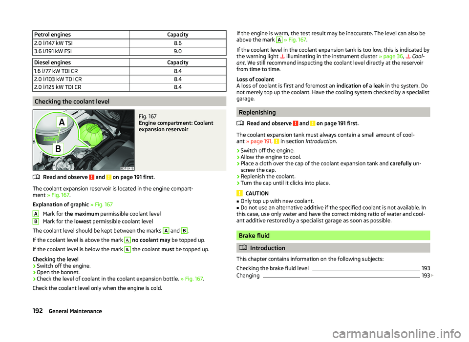
Petrol enginesCapacity2.0 l/147 kW TSI8.63.6 l/191 kW FSI9.0Diesel enginesCapacity1.6 l/77 kW TDI CR8.42.0 l/103 kW TDI CR8.42.0 l/125 kW TDI CR8.4
Checking the coolant level
Fig. 167
Engine compartment: Coolant
expansion reservoir
Read and observe and on page 191 first.
The coolant expansion reservoir is located in the engine compart-
ment » Fig. 167 .
Explanation of graphic » Fig. 167
Mark for the maximum permissible coolant level
Mark for the lowest permissible coolant level
The coolant level should be kept between the marks
A
and
B
.
If the coolant level is above the mark
A,
no coolant may be topped up.
If the coolant level is below the mark
B,
the coolant must be topped up.
Checking the level
›
Switch off the engine.
›
Open the bonnet.
›
Check the level of coolant in the coolant expansion bottle. » Fig. 167.
Check the coolant level only when the engine is cold.
ABIf the engine is warm, the test result may be inaccurate. The level can also be
above the mark A » Fig. 167 .
If the coolant level in the coolant expansion tank is too low, this is indicated by
the warning light
illuminating in the instrument cluster » page 36,
Cool-
ant . We still recommend inspecting the coolant level directly at the reservoir
from time to time.
Loss of coolant
A loss of coolant is first and foremost an indication of a leak in the system. Do
not merely top up the coolant. Have the cooling system checked by a specialist
garage.
Replenishing
Read and observe
and on page 191 first.
The coolant expansion tank must always contain a small amount of cool-
ant » page 191, in section Introduction .
›
Switch off the engine.
›
Allow the engine to cool.
›
Place a cloth over the cap of the coolant expansion tank and carefully un-
screw the cap.
›
Replenish the coolant.
›
Turn the cap until it clicks into place.
CAUTION
■ Only top up with new coolant.■Do not use an alternative additive if the specified coolant is not available. In
this case, use only water and have the correct mixing ratio of water and cool-
ant additive restored by a specialist garage as soon as possible.
Brake fluid
Introduction
This chapter contains information on the following subjects:
Checking the brake fluid level
193
Changing
193
192General Maintenance
Page 225 of 252
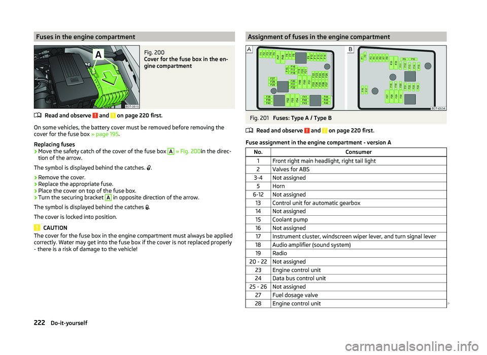
Fuses in the engine compartmentFig. 200
Cover for the fuse box in the en-
gine compartment
Read and observe and on page 220 first.
On some vehicles, the battery cover must be removed before removing the
cover for the fuse box » page 195.
Replacing fuses
›
Move the safety catch of the cover of the fuse box
A
» Fig. 200 in the direc-
tion of the arrow.
The symbol is displayed behind the catches. .
›
Remove the cover.
›
Replace the appropriate fuse.
›
Place the cover on top of the fuse box.
›
Turn the securing bracket
A
in opposite direction of the arrow.
The symbol is displayed behind the catches .
The cover is locked into position.
CAUTION
The cover for the fuse box in the engine compartment must always be applied
correctly. Water may get into the fuse box if the cover is not replaced properly
- there is a risk of damage to the vehicle!Assignment of fuses in the engine compartmentFig. 201
Fuses: Type A / Type B
Read and observe
and on page 220 first.
Fuse assignment in the engine compartment - version A
No.Consumer1Front right main headlight, right tail light2Valves for ABS3-4Not assigned5Horn6-12Not assigned13Control unit for automatic gearbox14Not assigned15Coolant pump16Not assigned17Instrument cluster, windscreen wiper lever, and turn signal lever18Audio amplifier (sound system)19Radio20 - 22Not assigned23Engine control unit24Data bus control unit25 - 26Not assigned27Fuel dosage valve28Engine control unit 222Do-it-yourself
Page 226 of 252
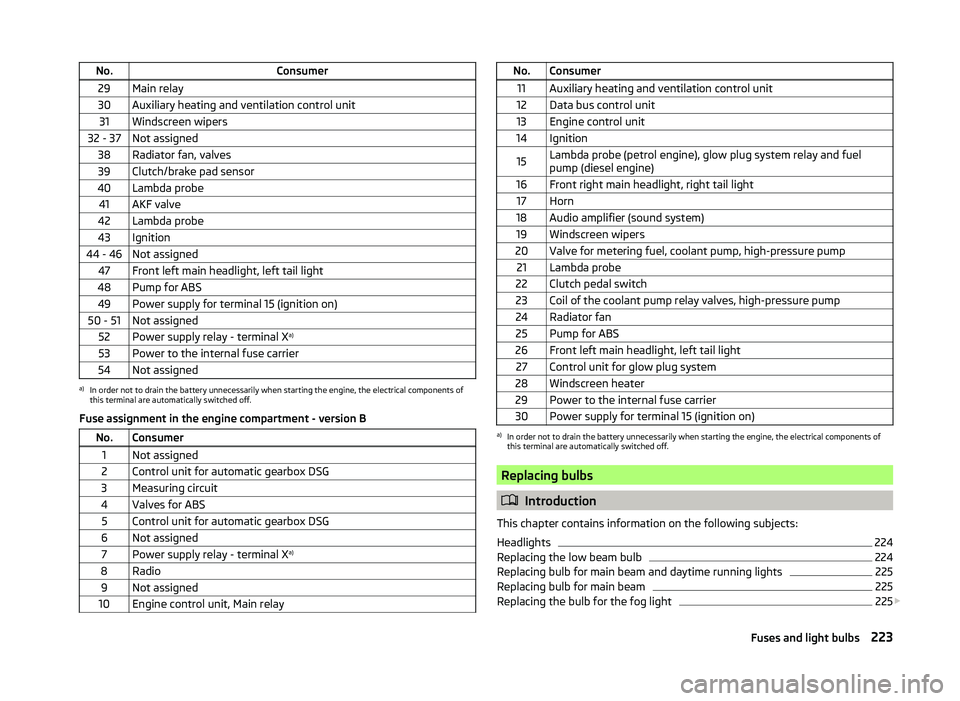
No.Consumer29Main relay30Auxiliary heating and ventilation control unit31Windscreen wipers32 - 37Not assigned38Radiator fan, valves39Clutch/brake pad sensor40Lambda probe41AKF valve42Lambda probe43Ignition44 - 46Not assigned47Front left main headlight, left tail light48Pump for ABS49Power supply for terminal 15 (ignition on)50 - 51Not assigned52Power supply relay - terminal Xa)53Power to the internal fuse carrier54Not assigneda)
In order not to drain the battery unnecessarily when starting the engine, the electrical components of
this terminal are automatically switched off.
Fuse assignment in the engine compartment - version B
No.Consumer1Not assigned2Control unit for automatic gearbox DSG3Measuring circuit4Valves for ABS5Control unit for automatic gearbox DSG6Not assigned7Power supply relay - terminal X a)8Radio9Not assigned10Engine control unit, Main relayNo.Consumer11Auxiliary heating and ventilation control unit12Data bus control unit13Engine control unit14Ignition15Lambda probe (petrol engine), glow plug system relay and fuel
pump (diesel engine)16Front right main headlight, right tail light17Horn18Audio amplifier (sound system)19Windscreen wipers20Valve for metering fuel, coolant pump, high-pressure pump21Lambda probe22Clutch pedal switch23Coil of the coolant pump relay valves, high-pressure pump24Radiator fan25Pump for ABS26Front left main headlight, left tail light27Control unit for glow plug system28Windscreen heater29Power to the internal fuse carrier30Power supply for terminal 15 (ignition on)a)
In order not to drain the battery unnecessarily when starting the engine, the electrical components of
this terminal are automatically switched off.
Replacing bulbs
Introduction
This chapter contains information on the following subjects:
Headlights
224
Replacing the low beam bulb
224
Replacing bulb for main beam and daytime running lights
225
Replacing bulb for main beam
225
Replacing the bulb for the fog light
225
223Fuses and light bulbs
Page 240 of 252
BootAutomatic retraction (Superb Combi)101
Extending variable loading floor105
Folding hook99
Non-closable side pocket (Superb Combi)102
Removable Light (Superb Combi)103
Roll up boot cover (Superb Combi)101
Side compartment with battery102
Boot cover (Superb Combi)101
Boot lid57
automatic locking58
Warning light36
(Superb Combi)58
Brake booster144
Brake fluid192
Checking193
Information messages35
specification193
Brake linings warning light
41
Brakes Brake assist systems
154
Brake booster144
Brake fluid193
Handbrake144
Information messages35
Running in149
Warning light35
Braking Information on braking
143
Break recommendation See Fatigue detection
165
Button in the driver's door Electrical power windows
61
C
Car care
173
Jack180
Car computer See multifunction display
44
Car park ticket holder89
Carrier Roof rack
108
Cavity protection180
CD changer136
Central locking50
Central locking button55
Changing brake fluid
193
bulbs223
Wheels205
Changing a wheel Follow-up work
206
Preliminary work206
Remove and attaching a wheel206
Changing brake fluid
193
Charging a vehicle battery196
Check Fit ball head properly
168
Checking Battery electrolyte level
195
Brake fluid193
Coolant192
Engine oil190
Oil level190
Windscreen washer fluid188
Checks Statutory checks
173
Children and safety22
Child safety Side airbag
24
Child safety lock55
Child seat Classification
25
ISOFIX25
on the front passenger seat23
TOP TETHER27
Use of child seats25
Use of ISOFIX child seats26
Chrome parts refer to Taking care of your vehicle178
Cigarette lighter91
Cleaning Alcantara
182
Covers of electrically heated seats182
Fabrics182
Headlight lenses179
Natural leather181
Plastic parts178
Synthetic leather182
Wheels180
Cleaning the vehicle Towing device
180
Cleaning vehicle176
Climatronic115
Air recirculation117
automatic mode116
Control elements115
Controlling blower118
Cooling system116
Defrosting windscreen118
Setting the temperature116
Clothes hook94
Cockpit 12-Volt power outlet
92
Ashtray91
Cigarette lighter91
General view29
Lighting73
Practical features88
Storage compartments88
Comfort control window
63
COMING HOME72
Compartments88
Components of the puncture repair kits209
Computer See multifunction display
44
237Index