warning SKODA SUPERB 2012 2.G / (B6/3T) Owner's Guide
[x] Cancel search | Manufacturer: SKODA, Model Year: 2012, Model line: SUPERB, Model: SKODA SUPERB 2012 2.G / (B6/3T)Pages: 235, PDF Size: 5.86 MB
Page 32 of 235

Vehicle locking/unlocking from the inside
Fig. 11
Central locking button
The doors and the boot lid can be unlocked/locked with the rocker switch on the
door opening lever of the driver or front passenger door » Fig. 11 even when the
ignition is not switched on.
The central locking button works only when the vehicle was not locked from the
outside and all doors are closed.
Locking
Press the symbol » Fig. 11 on the button. The symbol in the button comes on.
Unlocking
Press the symbol » Fig. 11 on the button. The symbol in the button is no longer
illuminated.
The following applies if your vehicle has been locked using the central locking
button.
› It is not possible to open the doors or the boot lid from the outside (safety fea-
ture, e.g. when stopping at traffic lights etc.).
› The vehicle doors can be unlocked and opened by pulling once on the door
opening lever.
› In the event of an accident in which the airbags are deployed, the locked doors
are automatically unlocked from the inside in order to enable rescuers to gain
access to the vehicle.
By pressing and holding down the symbol or on the rocker switch in the driv-
er's door, the windows can be conveniently closed or opened. WARNING
The central locking system also operates if the ignition is switched off. Chil-
dren should never be left unattended in the vehicle since it is difficult to pro-
vide assistance from the outside when the doors are locked. Locked doors
make it difficult for rescuers to get into the vehicle in an emergency - hazard! Note
If the safe securing system is activated » page 29, the door opening lever and the
central locking buttons do not operate. Ð Remote control
Introductory information
You can use the remote control key to:
› unlock and lock the vehicle,
› unlock or open the boot lid,
› open and close the windows
»
page 42, Window convenience operation .
The transmitter with the battery is housed in the handle of the remote control
key. The receiver is located in the interior of the vehicle. The operating range of
the remote control key is approx. 30 m. But this range of the remote control can
be reduced if the batteries are weak.
The key has a fold-open key bit which can be used for unlocking and locking the
car manually and also for starting the engine.
If a lost key is replaced or if the receiver unit has been repaired or replaced, the
system must be initialised by a ŠKODA Service Partner. Only then can the remote
control key be used again. Note
■ The remote control is automatically deactivated when the ignition is switched
on. ■ The operation of the remote control may temporarily be affected by interfer-
ence from transmitters close to the car and which operate in the same frequency
range (e.g. mobile phone, TV transmitter). £
30 Using the system
Page 33 of 235
■
The battery must be replaced if the central locking or anti-theft alarm system
does react to the remote control at less than 3
metres away » page 27.
■ If the driver door is open, the vehicle cannot be locked using the remote control
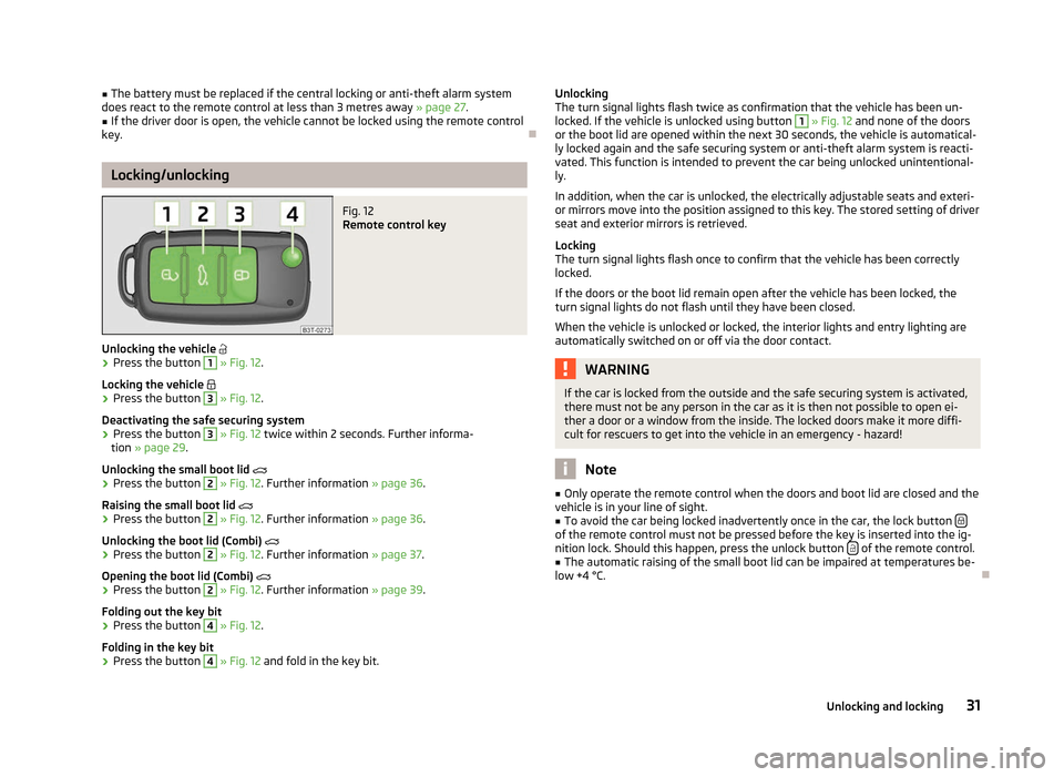
key. ÐLocking/unlocking
Fig. 12
Remote control key
Unlocking the vehicle
› Press the button 1
» Fig. 12.
Locking the vehicle
› Press the button 3
» Fig. 12.
Deactivating the safe securing system
› Press the button 3
» Fig. 12 twice within 2
seconds. Further informa-
tion » page 29.
Unlocking the small boot lid
› Press the button 2
» Fig. 12. Further information
» page 36.
Raising the small boot lid
› Press the button 2
» Fig. 12. Further information
» page 36.
Unlocking the boot lid (Combi)
› Press the button 2
» Fig. 12. Further information
» page 37.
Opening the boot lid (Combi)
› Press the button 2
» Fig. 12. Further information
» page 39.
Folding out the key bit
› Press the button 4
» Fig. 12.
Folding in the key bit
› Press the button 4
» Fig. 12 and fold in the key bit. Unlocking
The turn signal lights flash twice as confirmation that the vehicle has been un-
locked. If the vehicle is unlocked using button 1
» Fig. 12 and none of the doors
or the boot lid are opened within the next 30 seconds, the vehicle is automatical-
ly locked again and the safe securing system or anti-theft alarm system is reacti-
vated. This function is intended to prevent the car being unlocked unintentional-
ly.
In addition, when the car is unlocked, the electrically adjustable seats and exteri-
or mirrors move into the position assigned to this key. The stored setting of driver
seat and exterior mirrors is retrieved.
Locking
The turn signal lights flash once to confirm that the vehicle has been correctly
locked.
If the doors or the boot lid remain open after the vehicle has been locked, the
turn signal lights do not flash until they have been closed.
When the vehicle is unlocked or locked, the interior lights and entry lighting are
automatically switched on or off via the door contact. WARNING
If the car is locked from the outside and the safe securing system is activated,
there must not be any person in the car as it is then not possible to open ei-
ther a door or a window from the inside. The locked doors make it more diffi-
cult for rescuers to get into the vehicle in an emergency - hazard! Note
■ Only operate the remote control when the doors and boot lid are closed and the
vehicle is in your line of sight. ■ To avoid the car being locked inadvertently once in the car, the lock button of the remote control must not be pressed before the key is inserted into the ig-
nition lock. Should this happen, press the unlock button
of the remote control.
■ The automatic raising of the small boot lid can be impaired at temperatures be-
low +4 °C. Ð
31
Unlocking and locking
Page 35 of 235
Note
■ If the battery in the remote control key is weak or discharged, the vehicle may
not be unlocked or locked via the KESSY system. In this case, use the emergency
unlocking or emergency locking of the driver's door » page 35.
■ The KESSY system can find the valid key, even if it was left in the front area of
the vehicle's roof for example. Make sure you know where the valid remote con-
trol key is at all times. ■ When locking/unlocking the vehicle using the sensors 1
» Fig. 13 or 2
do not
use gloves or other objects that might prevent the hand from coming into direct
contact with the sensor.
■ If you unlock the vehicle by means of the sensor in the handle and do not open
a door or the boot lid within the next 30
seconds, the vehicle will lock again auto-
matically and the safe securing system or anti-theft alarm system will be reactiva-
ted. This function is intended to prevent the car being unlocked unintentionally. ÐProtection against inadvertently locking the key in the vehicle
If the key, which was used to lock the vehicle, remains in the vehicle in the area D
» Fig. 13 on page 32
after locking and closing all of the doors including the boot
lid, the protection against inadvertently locking the key in the vehicle is activated
and the vehicle unlocks itself again.
The following message is displayed in the information display or display of the in-
strument cluster: Key in vehicle. or KEY IN VEHICLE.
Additionally, on vehicles which are fitted with the anti-theft alarm system, an au-
dible signal sounds. ÐMessages in the instrument cluster display
■ Key not found. or No Key
This message is displayed when you wish to start the engine and the system can-
not detect a valid key in the vehicle. This can occur if the key is outside the vehi-
cle, the battery in the key is discharged, the key is defective or the electromag-
netic field is strongly disturbed. This message is also displayed when the ignition
is switched on or the engine is running and the system cannot detect a valid key
in the vehicle.
■ Keyless faulty. or CHECK KEYLESS.
Error in the KESSY system; seek help from a
ŠKODA specialist garage. ■
Renew key battery! or KEY BATTERY
Low voltage of the remote control key battery, change the battery. Ð Parking the vehicle
If the vehicle is not unlocked within 60 or 90 hours, the sensors 1
» Fig. 13
on
page 32 and 2
in the handle of the front passenger's door are automatically de-
activated.
Activation after 60 hours
› Unlock the driver's door using the sensor 2
» Fig. 13 on page 32
.
› Press the handle of the boot lid.
› Unlock the vehicle using the button on the remote control key,
› Unlocking the driver's door in an emergency
» page 35.
Activation after 90 hours
› Unlock the vehicle using the button on the remote control key,
› Unlocking the driver's door in an emergency
» page 35.Ð Anti-theft alarm system
Introductory information
The anti-theft alarm system increases the level of protection against people
seeking to break into the vehicle. The system triggers audible and visual warning
signals if an attempt is made to break into the vehicle.
How is the alarm system activated?
The anti-theft alarm system is activated when the vehicle is locked with the radio
remote control or the key in the driver's door . The door contact monitoring is ac-
tivated approx. 15 seconds after the locking. The interior and the towing protec-
tion monitoring are activated approx. 30 seconds after the locking. If a door is
opened during activation, the monitoring is only activated 5 seconds after closing.
How is the alarm system deactivated?
The alarm system is deactivated by pressing the unlock button on the radio re-
mote control. The anti-theft alarm system is reactivated if the vehicle is not
opened within 30 seconds after transmitting the radio signal.
The alarm system is also deactivated if you unlock the driver door using the key
within 45 seconds of locking the vehicle. £
33
Unlocking and locking
Page 37 of 235
Emergency unlocking and locking
Unlocking and locking the driver's door
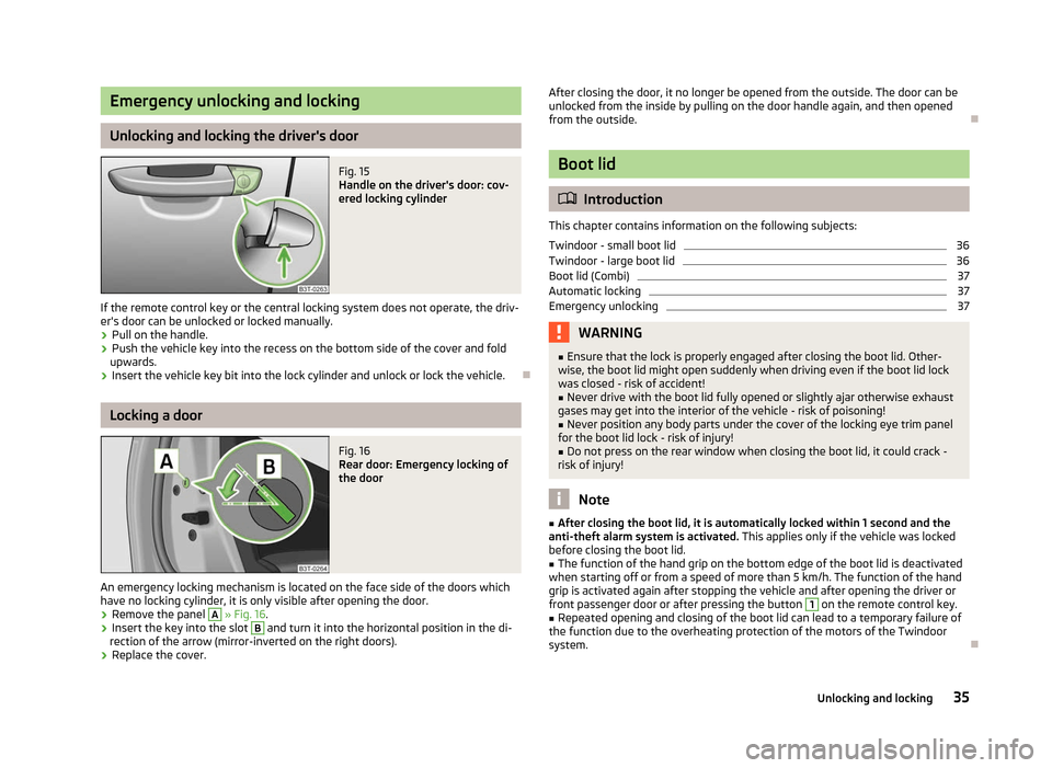
Fig. 15
Handle on the driver's door: cov-
ered locking cylinder
If the remote control key or the central locking system does not operate, the driv-
er's door can be unlocked or locked manually.
› Pull on the handle.
› Push the vehicle key into the recess on the bottom side of the cover and fold
upwards.
› Insert the vehicle key bit into the lock cylinder and unlock or lock the vehicle. ÐLocking a door
Fig. 16
Rear door: Emergency locking of
the door
An emergency locking mechanism is located on the face side of the doors which
have no locking cylinder, it is only visible after opening the door.
› Remove the panel A
» Fig. 16
.
› Insert the key into the slot B
and turn it into the horizontal position in the di-
rection of the arrow (mirror-inverted on the right doors).
› Replace the cover. After closing the door, it no longer be opened from the outside. The door can be
unlocked from the inside by pulling on the door handle again, and then opened
from the outside.
Ð Boot lid
ä
Introduction
This chapter contains information on the following subjects:
Twindoor - small boot lid 36
Twindoor - large boot lid 36
Boot lid (Combi) 37
Automatic locking 37
Emergency unlocking 37
WARNING
■ Ensure that the lock is properly engaged after closing the boot lid. Other-
wise, the boot lid might open suddenly when driving even if the boot lid lock
was closed - risk of accident!
■ Never drive with the boot lid fully opened or slightly ajar otherwise exhaust
gases may get into the interior of the vehicle - risk of poisoning!
■ Never position any body parts under the cover of the locking eye trim panel
for the boot lid lock - risk of injury! ■ Do not press on the rear window when closing the boot lid, it could crack -
risk of injury! Note
■ After closing the boot lid, it is automatically locked within 1 second and the
anti-theft alarm system is activated. This applies only if the vehicle was locked
before closing the boot lid. ■ The function of the hand grip on the bottom edge of the boot lid is deactivated
when starting off or from a speed of more than 5
km/h. The function of the hand
grip is activated again after stopping the vehicle and after opening the driver or
front passenger door or after pressing the button 1
on the remote control key.
■ Repeated opening and closing of the boot lid can lead to a temporary failure of
the function due to the overheating protection of the motors of the Twindoor
system. Ð
35
Unlocking and locking
Page 42 of 235

Adjusting the top position of the lid
First read and observe the introductory information given on page 38.If the space for opening the lid is restricted (e.g. height of garage) or for more
convenient operation (e.g. according to a person's height), it is possible to adjust
the top position of the boot lid.
Adjusting
› Stop the lid in the desired position (electrically or manually).
› Press the inner button B
» Fig. 21 on page 38 and press and hold it for approx.
3 seconds. Storing the position in the memory of the control unit is confirmed
with an audible signal.
Deleting the adjusted position
› Carefully lift up the lid manually to the maximum opening position.
› Press and hold the inner button B
» Fig. 21 on page 38 for approx. 3
seconds.
An audible signal sounds and the height which was originally set is deleted from
the memory of the control unit, while the basic position of the top lid position is
again set. Note
■ The lid always opens at the height which was last stored in the memory of the
control unit. ■ The top position which is reached when the lid opens automatically, is always
lower than the maximum top position which can be reached when the lid is
opened manually. ÐOperational problems
First read and observe the introductory information given on page
38.If the battery is disconnected and reconnected while the boot lid is open, it is
necessary to activate the electric boot lid system. Activation refers to the initiali-
sation of the control unit by manually closing the lid. Thus, the end position of the
lid is stored under fully closed in secured lock.
Possible malfunctions of the electric boot lid:
ä
ä Examples of operational malfunctions
Description of the malfunc-
tion Possible solutions
The lid cannot be lifted out of
the lock. Emergency unlocking of the lid
» page 37
The lid does not react to an
opening signal Remove the possible obstacle (e.g. snow), open
the lid again » page 39
Press the handle on the lower edge of the boot
lid and pull the lid upwards
The lid remains in the top po-
sition Manually close the lid (slowly and without sud-
den movements) Ð
Electric power windows
ä
Introduction
This chapter contains information on the following subjects:
Window open/close 41
Window in the front passenger door and the rear doors open/close 42
Force limiter of the power windows 42
Window convenience operation 42
Operational faults 43
WARNING
■ If the vehicle is locked from the outside, do not leave anybody in the vehicle
as it is not possible to open the windows from the inside in the event of an
emergency.
■ The system is fitted with a force limiter » page 42. If there is an obstacle,
the closing process is stopped and the window goes down by several centi-
metres. The windows should nevertheless be closed carefully! Otherwise
these can cause severe crushing injuries!
■ It is recommended to deactivate the electrically operated power windows in
the rear doors (safety pushbutton) S
» Fig. 23
on page 41 when children
are being transported on the rear seats. £
40 Using the system
Page 45 of 235
Operational faults
First read and observe the introductory information and safety warn-
ings on page 40.
Electrically operated power windows do not operate
If the battery has been disconnected and then reconnected while the window
was opened, the electrically operated power windows do not operate. The system
must be activated. Proceed as follows in order to re-establish the function:
› switch on the ignition;
› pull the top edge of the button to close the window;
› release the button;
› pull the relevant button upwards again for approx. 3
seconds.
Operation in winter
In the winter, ice accumulating on the surface of the window may cause there to
be more resistance when closing the window. The window will stop and move
back several centimetres.
It is necessary to deactivate the force limiter to close the window » page 42.ÐElectric sliding/tilting roof
Introductory information
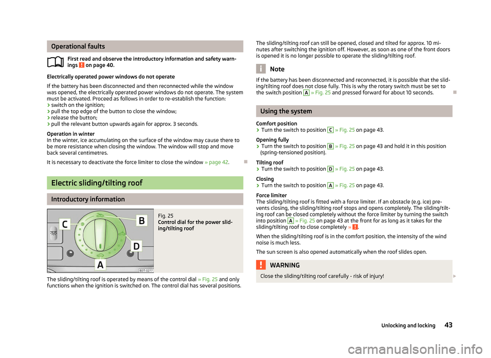
Fig. 25
Control dial for the power slid-
ing/tilting roof
The sliding/tilting roof is operated by means of the control dial » Fig. 25 and only
functions when the ignition is switched on. The control dial has several positions.
ä
The sliding/tilting roof can still be opened, closed and tilted for approx. 10
mi-
nutes after switching the ignition off. However, as soon as one of the front doors
is opened it is no longer possible to operate the sliding/tilting roof. Note
If the battery has been disconnected and reconnected, it is possible that the slid-
ing/tilting roof does not close fully. This is why the rotary switch must be set to
the switch position A
» Fig. 25 and pressed forward for about 10
seconds.Ð Using the system
Comfort position
› Turn the switch to position C
» Fig. 25 on page 43.
Opening fully
› Turn the switch to position B
» Fig. 25 on page 43 and hold it in this position
(spring-tensioned position).
Tilting roof
› Turn the switch to position D
» Fig. 25 on page 43.
Closing
› Turn the switch to position A
» Fig. 25 on page 43.
Force limiter
The sliding/tilting roof is fitted with a force limiter. If an obstacle (e.g. ice) pre-
vents closing, the sliding/tilting roof stops and opens completely. The sliding/tilt-
ing roof can be closed completely without the force limiter by turning the switch
into position A
» Fig. 25 on page 43 at the front for as long as it takes for the
sliding/tilting roof to close completely » .
When the sliding/tilting roof is in the comfort position, the intensity of the wind
noise is much less.
The sun screen is also opened automatically when the roof slides open. WARNING
Close the sliding/tilting roof carefully - risk of injury! £
43
Unlocking and locking
Page 46 of 235
CAUTION
During the winter it may be necessary to remove any ice and snow in the vicinity
of the sliding/tilting roof before opening it to prevent any damage to the opening
mechanism and seal. ÐConvenience operation
An open sliding/tilting roof can also be closed from the outside.
› Press and hold the lock button
on the remote control key or hold the key in
the locking cylinder of the driver's door in the lock position, or with the KESSY
system, keep your finger on the sensor 1
» Fig. 13 on page 32 » .
The closing operation stops immediately when you release the key or the lock
button. WARNING
Close the sliding/tilting roof carefully - risk of injury! The force limiter does not
operate with the convenience closing. ÐElectric sliding/tilting roof with solar cells
If there is sufficient bright sunlight, the solar cells on the sliding/tilting roof deliv-
er power for the fresh air blower. Further information » page 97, Climatronic
(automatic air conditioning system) .
The operation of the sliding/tilting roof with solar cells is the same as of a normal
sliding/tilting roof. Ð Emergency operation
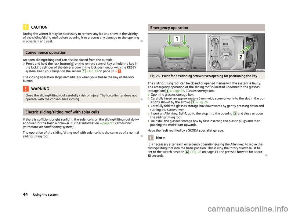
Fig. 26
Point for positioning screwdriver/opening for positioning the key
The sliding/tilting roof can be closed or opened manually if the system is faulty.
The emergency operation of the sliding roof is located underneath the glasses
storage box 1
» page 87,
Glasses storage box .
› Open the glasses storage box.
› Carefully insert an approximately 5 mm wide screwdriver into the slot in the po-
sitions shown by the arrows 1
» Fig. 26.
› Carefully fold the glasses storage box downwards by gently pressing down and
turning the screwdriver.
› Insert an Allen key, SW 4, up to the stop into the opening 2
and close or open
the sliding/tilting roof.
› Reinstall the glasses storage box by first inserting the plastic plugs and then
pushing the entire part upwards.
Have the fault rectified by a
ŠKODA specialist garage. Note
It is necessary after each emergency operation (using the Allen key) to move the
sliding/tilting roof into the basic position. This is why the rotary switch must be
set to the switch position A
» Fig. 25 on page 43 and pressed forward for about
10 seconds. Ð
44 Using the system
Page 47 of 235
Panoramic sliding roof (Combi)
Introductory information
The panoramic sliding roof with sun screen can only be operated with the rotary
switch when the ignition is switched on » Fig. 27 on page
45. The control dial
has several positions.
The panoramic sliding roof or sun screen can still be opened, closed and tilted for
approx. 10 minutes after switching the ignition off. However, as soon as one of
the front doors is opened it is no longer possible to operate the panoramic sliding
roof and sun screen. Note
If the battery has been disconnected and reconnected, it is possible that the slid-
ing/tilting roof does not close fully. This is why the rotary switch must be set to
the switch position A
» Fig. 27
on page 45 and pressed forward for about
10 seconds. ÐUsing the system
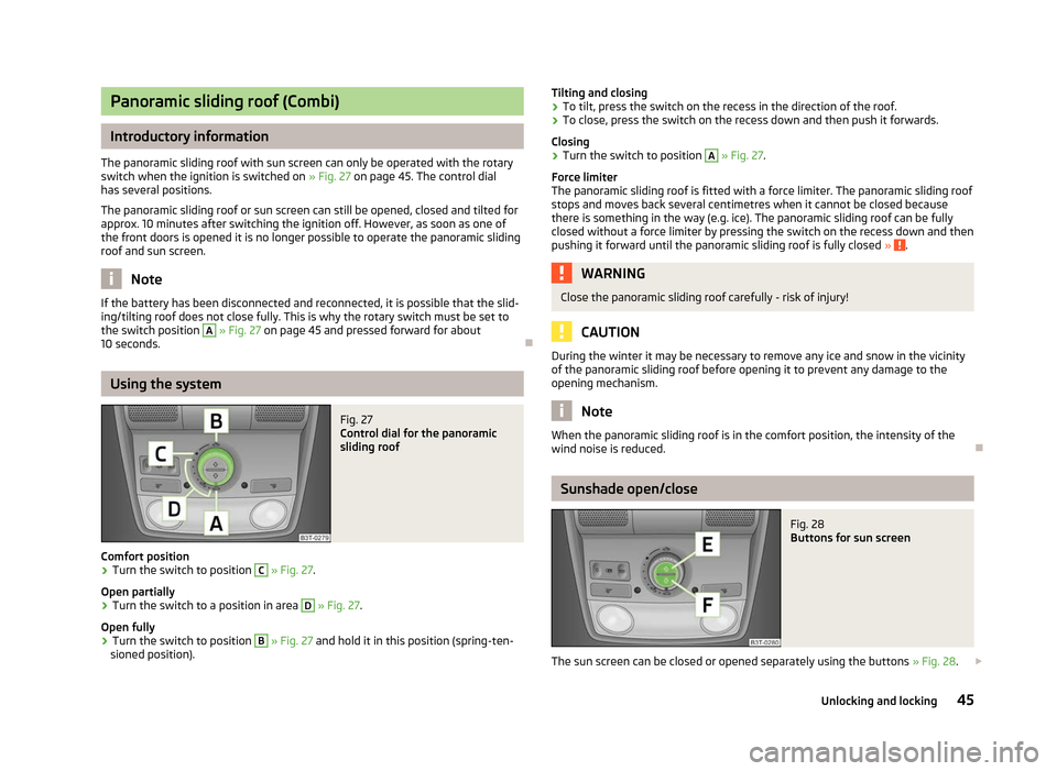
Fig. 27
Control dial for the panoramic
sliding roof
Comfort position
› Turn the switch to position C
» Fig. 27.
Open partially
› Turn the switch to a position in area D
» Fig. 27
.
Open fully
› Turn the switch to position B
» Fig. 27 and hold it in this position (spring-ten-
sioned position). Tilting and closing
› To tilt, press the switch on the recess in the direction of the roof.
› To close, press the switch on the recess down and then push it forwards.
Closing
› Turn the switch to position A
» Fig. 27.
Force limiter
The panoramic sliding roof is fitted with a force limiter. The panoramic sliding roof
stops and moves back several centimetres when it cannot be closed because
there is something in the way (e.g. ice). The panoramic sliding roof can be fully
closed without a force limiter by pressing the switch on the recess down and then
pushing it forward until the panoramic sliding roof is fully closed » .
WARNING
Close the panoramic sliding roof carefully - risk of injury! CAUTION
During the winter it may be necessary to remove any ice and snow in the vicinity
of the panoramic sliding roof before opening it to prevent any damage to the
opening mechanism. Note
When the panoramic sliding roof is in the comfort position, the intensity of the
wind noise is reduced. Ð Sunshade open/close
Fig. 28
Buttons for sun screen
The sun screen can be closed or opened separately using the buttons » Fig. 28.£
45
Unlocking and locking
Page 50 of 235

Lights and visibility
Lights
ä
Introduction
This chapter contains information on the following subjects:
Switching lights on and off 49
DAY LIGHT function (Daylight driving light) 49
Automatic driving lamp control 49
Parking light 50
COMING HOME/LEAVING HOME function 50
Adaptive headlights (AHL) 51
Fog lights 52
Fog lights with the function CORNER 52
Rear fog lights 52
Instrument lighting 53
Headlight beam adjustment 53
Switches for the hazard warning light system 53
Turn signal and main beam lever 54
On models fitted with right-hand steering the position of certain switches differs
from that shown in » Fig. 30 on page
49. The symbols which mark the switch
positions are identical, however.
The low beam continues to shine while the ignition is switched on and the light
switch is in the position or . After switching off the ignition, the low beam
is switched off automatically and only the side lights come on. The side lights also
go out after the ignition key is removed. WARNING
■ Never drive with only the side lights on! The side lights are not bright
enough to light up the road sufficiently in front of you or to be seen by other
oncoming traffic. Therefore always switch on the low beam when it is dark or
if visibility is poor.
■ The automatic driving lamp control
only operates as a support and does
not release the driver from his responsibility to check the light and, if necessa-
ry, to switch on the light depending on the light conditions. The light sensor
cannot, for example, detect rain or snow. Under these conditions we recom-
mend switching on the low beam or fog lights! CAUTION
■ The activation of the lights should only be undertaken in accordance with na-
tional legal requirements.
■ The driver is always responsible for the correct settings and use of the lights. Note
■ If the light switch is in the position , the ignition key is removed and the driv-
er's door is open, an audible warning signal will sound. The audible warning signal
is switched off by means of the door contact when the driver's door is closed (ig-
nition off), however, the side lights remain on to illuminate the parked vehicle if
necessary. ■ If there is a fault in the light switch, the low beam comes on automatically.
■ In the event of cool or humid weather conditions, the headlights can be misted
up from inside. The temperature difference between interior and external area of
the headlight lenses is decisive. When the driving lights are switched on, the light
outlet surfaces are free from mist after a short period, although the headlight
lenses may still be misted up in the peripheral areas. It also concerns reverse light
and turn signal lights. This mist has no influence on the life of the lighting system. Ð
48 Using the system
Page 53 of 235
Note
■ If the COMING HOME/LEAVING HOME function is switched on constantly, the
battery will be heavily discharged particularly over short distances. ■ The illumination period for the COMING HOME/LEAVING HOME function can be
changed by means of the information display. ÐAdaptive headlights (AHL)
First read and observe the introductory information and safety warn-
ings on page 48.
Switching on
›
Turn the light switch
» Fig. 31 on page 49 to position
.
The AHL system is activated if:
› the light sensor recognises a low light intensity,
› no reverse gear is engaged,
› the operation mode “tourist light” is not switched on.
The light sensor switches on the full outer illumination at low light intensity.
The AHL system makes it possible to change the length and width of illumination
from the headlights. The length and width of illumination changes automatically
in relation to the vehicle speed and the use of the windscreen wiper.
The AHL system operates in the following modes.
Out of town mode
The “out of town” mode is a basic mode. The dispersion of the cone of light in
front of the vehicle is similar to the low beam. The mode is active if none of the
following modes are active.
Rain mode
In the “rain” mode the dispersion of the cone of light in front of the vehicle is wid-
er and the width of illumination is shorter, so that during bad weather (rain) the
dazzling of the oncoming drivers can be reduced. The mode is activated at speeds
of 15 – 70 km/h and if the windscreen wipers continuously operate for a period of
time longer than 2 minutes. The mode is deactivated when dropping below or ex-
ceeding the set speed limit or if the windscreen wipers have been switched off
for a period of time longer than 8 minutes. ä
City mode
In the
“city” mode, the dispersion of the cone of light in front of the vehicle is wid-
er and the width of illumination is shorter. The aim is to illuminate also the adja-
cent footpaths, crossings, pedestrian crossings, etc. The mode is active at speeds
of 15-50 km/h.
Motorway mode
In the “motorway” mode, the dispersion of the cone of light is adapted so that it
also illuminates the left (or right) 1)
lane of the motorway, so that the driver can re-
act in time to an obstacle or any other danger. The mode is activated gradually
from a speed of 90 km/h. It is most effective at speeds above 120 km/h.
Tourist light
This mode makes it possible to drive in countries with opposing traffic system,
driving on the left/right, without dazzling the oncoming vehicles. When the “tou-
rist light” mode is active, the above-mentioned modes and the side swivel of the
headlights is deactivated.
The “tourist light” mode is activated/deactivated via the information display in
the menu:
■ Settings
■ Travel mode
■ Off
■ Switched on
Cornering lights
The cornering lights are used to illuminate the curves by means of the cone of
light swivelling together with the front headlight with Xenon lights. This function
is active when the speed of the car increases to more than 10 km/h. WARNING
If the cornering lights are defective, the headlights are automatically lowered
to the emergency position, which prevents a possible dazzling of oncoming
traffic. Thus the illuminated length of the road is shortened. Drive carefully
and visit a ŠKODA specialist garage as soon as possible. Note
The AHL system complements the functions of the fog lights with the function
CORNER » page 52 and the function of the dynamic headlight beam adjustment. Ð1)
It is valid for vehicles which are designed for driving on the left.
51
Lights and visibility