display SKODA SUPERB 2013 2.G / (B6/3T) Workshop Manual
[x] Cancel search | Manufacturer: SKODA, Model Year: 2013, Model line: SUPERB, Model: SKODA SUPERB 2013 2.G / (B6/3T)Pages: 274, PDF Size: 17.31 MB
Page 130 of 274

Button/wheelActionRadioTVAudio sourcesDVD videoNavigation1PressChange audio source2
PressSwitch tone off/on (MUTE )Interrupt current
navigation an-nouncement2Turn upwardsIncrease the volume2Turn downwardsDecrease the volume3Press brieflySkip to next channelSkip to next channelSkip to next trackSkip to next chapterNo functionStop traffic announcement3Press and hold but- tonNo functionFast forwardNo function4
Press brieflySwitch to previous channelSwitch to previouschannelSwitch to start of tracka)Switch to previous
chapterNo functionStop traffic announcement4Press and hold but- tonNo functionFast rewindNo function5Turn upwardsSwitch to previous channel and displayList of stored/accessible channelsSkip to next channelSkip to next trackSkip to next chapterShow the option tostop navigation ordisplay the list of recent destina- tions5Turn downwardsSwitch to the next channel and displayList of stored / accessible channelsSwitch to previous channelSwitch to start of tracka)Switch to previous
chapter6Press brieflyCall up the main menua)
To go to the previous track, press the adjustment wheel twice or rotate it by two positions.
AUX- and MDI inputs
First read and observe the introductory information given on page 126.
The AUX- and MDI inputs are used to connect external audio sources (e.g. iPod or
MP3 player) and to play back music from these devices via the factory-fitted radio
or navigation system.
The AUX-input is located in the storage compartment below the front armrest
and is marked with .
The MDI input is located in the storage compartment below the front armrest.
For a description of use, refer to the operating instructions for the relevant radio or navigation system.
127Communication and multimedia
Page 135 of 274
For the sake of the environmentDo not warm up the engine while the vehicle is stationary. If possible, start your
journey as soon as the engine has started. Through this the engine reaches its operating temperature more rapidly and the pollutant emissions are lower.
Note
After switching off the ignition, the radiator fan may intermittently continue to
operate for approx. 10 minutes.
Electronic immobilizer
First read and observe the introductory information and safety warn-ings
on page 131.
An electronic chip is integrated in the head of the key. The immobiliser is deacti-
vated with the aid of this chip when the key is inserted in the ignition lock.
The electronic immobiliser is automatically activated when the ignition key is
withdrawn from the lock.
The engine will not start if a non-authorized ignition key is used.
The following message is shown in the information cluster display.
Immobilizer active.
IMMOBILISER
Ignition Switch
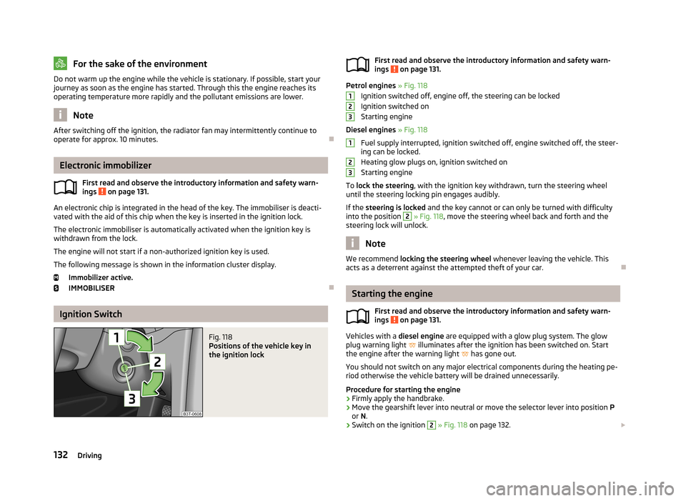
Fig. 118
Positions of the vehicle key in
the ignition lockFirst read and observe the introductory information and safety warn-
ings on page 131.
Petrol engines » Fig. 118
Ignition switched off, engine off, the steering can be locked
Ignition switched on
Starting engine
Diesel engines » Fig. 118
Fuel supply interrupted, ignition switched off, engine switched off, the steer-
ing can be locked.
Heating glow plugs on, ignition switched on
Starting engine
To lock the steering , with the ignition key withdrawn, turn the steering wheel
until the steering locking pin engages audibly.
If the steering is locked and the key cannot or can only be turned with difficulty
into the position
2
» Fig. 118 , move the steering wheel back and forth and the
steering lock will unlock.
Note
We recommend locking the steering wheel whenever leaving the vehicle. This
acts as a deterrent against the attempted theft of your car.
Starting the engine
First read and observe the introductory information and safety warn-
ings
on page 131.
Vehicles with a diesel engine are equipped with a glow plug system. The glow
plug warning light
illuminates after the ignition has been switched on. Start
the engine after the warning light
has gone out.
You should not switch on any major electrical components during the heating pe- riod otherwise the vehicle battery will be drained unnecessarily.
Procedure for starting the engine
›
Firmly apply the handbrake.
›
Move the gearshift lever into neutral or move the selector lever into position P
or N.
›
Switch on the ignition
2
» Fig. 118 on page 132.
123123132Driving
Page 136 of 274
›Depress and hold the clutch pedal (vehicles with a manual gearbox) or brake
pedal (vehicles with an automatic gearbox) until the engine starts.›
Turn the key into position
3
to the stop and release immediately after the en-
gine has been started – do not apply the accelerator.
After letting go, the vehicle key will return to position
2
.
If the engine does not start within 10 seconds, turn the key to position
1
. Repeat
the start-up process after approx. half a minute.
›
Release the handbrake.
Vehicles with manual transmission
The engine will not start if the clutch pedal is not depressed.
The following message is shown in the information cluster display.
Depress clutch to start.CLUTCH
Vehicles with automatic transmission
The engine will not start if the brake pedal is not depressed.
The warning light
lights up in the instrument cluster and the following mes-
sage appears in the display.
Apply the brake to start.
BRAKE
CAUTION
■ If the engine does not start up after a second attempt, one of the following
fuses may be defective. ■Petrol engine - fuse for the electric fuel pump.
■ Diesel engine - fuse for the control unit for glow plugs or glow plug relay and
fuel pump.■
Check the fuse and replace if necessary » page 244, or seek assistance from a
specialist garage.
Stopping the engine
First read and observe the introductory information and safety warn-ings
on page 131.
Switch off the engine by turning the ignition key into position
1
» Fig. 118 on
page 132.
For vehicles with automatic transmission, the ignition key can only be removed if
the selector lever is in position P.
Starting and stopping the engine - KESSY
Introduction
This chapter contains information on the following subjects:
Steering lock / unlock
134
Switching on the ignition
135
Starting the engine
135
Switching off the ignition
136
Switching off the engine
136
Emergency start-up of the engine
136
Emergency ignition shutoff system
136
The KESSY system (Keyless Entry Exit System, hereinafter referred to only as sys- tem) allows the switching on or switching off of the ignition and starting or stop-ping of the engine without the active use of the key.
A key must be in the vehicle to unlock the steering, switch on the ignition and
start the vehicle. When travelling the key must be in the vehicle.
The engine running noises may louder at first be louder for a short time afterstarting the cold engine. This is quite normal and is not an operating problem.
WARNING■ Never leave the key in the vehicle when you exit the vehicle. This is particu-
larly important if children are left in the vehicle. Children could otherwise start
the engine for example – risk of accident or injury!■
Never leave the vehicle unattended with the engine running.
■
Never switch off the engine before the vehicle is stationary – risk of acci-
dent!
133Starting-off and Driving
Page 138 of 274

If the system does not unlock the steering at the first time (for example when the
front wheels are in contact with an obstacle), then two more unlocking attempts
are performed automatically.
If the steering is still not unlocked, then the following message is displayed on
the display of the instrument cluster.
Move the steering wheel!
MOVE STEERING WHEEL
Slightly move the steering wheel and the system will make up to 3 more attempts
to unlock after 2 seconds. At the same time, the indicator light flashes.
If the steering is still not unlocked, to try to eliminate the possible cause and then
repeat the unlocking attempt.
Switching on the ignition
First read and observe the introductory information and safety warn-
ings
on page 133.
›
Press the starter button » Fig. 119 on page 134 briefly.
The ignition is switched on.
Note
The ignition is switched on when indicated by the lighting up of certain indicator
lamps in the instrument cluster.
Starting the engine
First read and observe the introductory information and safety warn-
ings
on page 133.
Vehicles with a diesel engine are equipped with a glow plug system. The glow
plug warning light
illuminates after the ignition has been switched on. Start
the engine after the warning light
has gone out.
You should not switch on any major electrical components during the heating pe- riod otherwise the vehicle battery will be drained unnecessarily.
Procedure for starting the engine›Firmly apply the handbrake.›
Move the gearshift lever into neutral or move the selector lever into position P
or N.
›
Depress and hold the clutch pedal (vehicles with a manual gearbox) or brake
pedal (vehicles with an automatic gearbox) until the engine starts.
›
» Fig. 119 on page 134Press and hold 1)
the starter button until the engine starts.
›
Release the handbrake.
Vehicles with manual transmission
The engine will not start if the clutch pedal is not depressed.
The following message is shown in the information cluster display.
Depress clutch to start.CLUTCH
Vehicles with automatic transmission
The engine will not start if the brake pedal is not depressed.
The warning light
lights up in the instrument cluster and the following mes-
sage appears in the display.
Apply the brake to start.
BRAKE
CAUTION
■ If the engine does not start up after a second attempt, one of the following
fuses may be defective. ■Petrol engine - fuse for the electric fuel pump.
■ Diesel engine - fuse for the control unit for glow plugs or glow plug relay and
fuel pump.■
Check the fuse and replace if necessary » page 244, or seek assistance from a
specialist garage.
1)
On vehicles with the START-STOP system, it is sufficient to press the starter button briefly. The mo-
tor will then automatically start.
135Starting-off and Driving
Page 139 of 274

Switching off the ignitionFirst read and observe the introductory information and safety warn-ings
on page 133.
›
Press the starter button » Fig. 119 on page 134 briefly.
The ignition is switched off.
The ignition can be switched off up to a speed of 2 km/h.
On vehicles with manual transmission , the clutch pedal must not be depressed to
switch off the ignition, otherwise the system will try to start.
For automatic transmission vehicles, the brake pedal must not be depressed,
otherwise the system will try to start.
If the driver's door is opened while the igition is on, an audible signal sounds andthe following message appears in the instrument cluster display.
Ignition on!
IGNITION ON
When leaving the vehicle always switch off the ignition.
Switching off the engine
First read and observe the introductory information and safety warn-ings
on page 133.
›
Stop the vehicle.
›
Press the starter button » Fig. 119 on page 134.
The engine and the ignition are switched off simultaneously.
Emergency start-up of the engineFig. 120
Emergency start-up of engine
First read and observe the introductory information and safety warn- ings on page 133.
If the authorisation check for the key fails, the following message appears in the
instrument cluster display.
Key not found.
NO KEY
The emergency start-up must be completed.
› Press the starter button directly with the key
» Fig. 120.
or
› Press the starter button and then hold the key to the starter button.
Note
During an emergency start-up of the engine, the key bit must face the starter
button » Fig. 120 .
Emergency ignition shutoff system
First read and observe the introductory information and safety warn-
ings
on page 133.
The ignition can be turned off in an emergency even when travelling at a speed of
more than 2 km / hr.
›
Press the starter button » Fig. 119 on page 134 for longer than 1 second or twice
within 1 second.
136Driving
Page 141 of 274
Low brake fluid level
An insufficient level of brake fluid may result in problems in the brake system. The
level of the brake fluid is monitored electronically » page 15, Brake system .
Brake booster
The brake booster increases the pressure generated with the brake pedal. The
brake booster only operates when the engine is running.
Handbrake
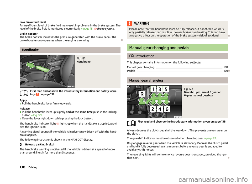
Fig. 121
Handbrake
First read and observe the introductory information and safety warn- ings on page 137.
Apply
›
Pull the handbrake lever firmly upwards.
Release
›
Pull the handbrake lever up slightly and at the same time push in the locking
button » Fig. 121 .
›
Move the lever right down while pressing the lock button.
The handbrake indicator light
lights up when the handbrake is applied, provi-
ded the ignition is on.
A warning signal sounds if the vehicle is inadvertently driven off with the hand-
brake applied.
The following instruction is shown in the MAXI DOT display. Release parking brake!
The handbrake warning is activated if the vehicle is driven at a speed of more
than around 5 km/h for more than 3 seconds.
WARNINGPlease note that the handbrake must be fully released. A handbrake which is
only partially released can result in the rear brakes overheating. This can have a negative effect on the operation of the brake system – risk of accident!
Manual gear changing and pedals
Introduction
This chapter contains information on the following subjects:
Manual gear changing
138
Pedals
139
Manual gear changing
Fig. 122
Gearshift pattern of 5 gear or
6 gear manual gearbox
First read and observe the introductory information given on page 138.
Always depress the clutch pedal all the way down. This prevents uneven wear on the clutch.
The gearshift indicator must be observed when changing gear » page 24.
Only engage reverse gear when the vehicle is stationary. Depress the clutch pedal
and hold it fully depressed. Wait a moment before reverse gear is engaged to
avoid any shift noises.
The reversing lights will come on once reverse gear is engaged, provided the igni- tion is on.
138Driving
Page 143 of 274
Modes and use of selector leverFig. 123
Selector lever / display
Fig. 124
Shiftlock button
First read and observe the introductory information and safety warn-
ings on page 139.
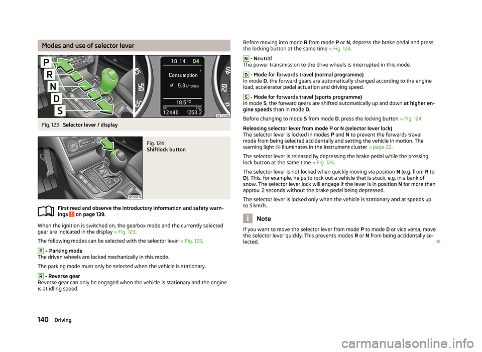
When the ignition is switched on, the gearbox mode and the currently selected gear are indicated in the display » Fig. 123.
The following modes can be selected with the selector lever » Fig. 123.
P
– Parking mode
The driven wheels are locked mechanically in this mode.
The parking mode must only be selected when the vehicle is stationary.
R
- Reverse gear
Reverse gear can only be engaged when the vehicle is stationary and the engine
is at idling speed.
Before moving into mode R from mode P or N, depress the brake pedal and press
the locking button at the same time » Fig. 124.N
- Neutral
The power transmission to the drive wheels is interrupted in this mode.
D
- Mode for forwards travel (normal programme)
In mode D, the forward gears are automatically changed according to the engine
load, accelerator pedal actuation and driving speed.
S
- Mode for forwards travel (sports programme)
In mode S, the forward gears are shifted automatically up and down at higher en-
gine speeds than in mode D.
Before changing to mode S from mode D, press the locking button » Fig. 124
Releasing selector lever from mode P or N (selector lever lock) The selector lever is locked in modes P and N to prevent the forwards travel
mode from being selected accidentally and setting the vehicle in motion. The
warning light
illuminates in the instrument cluster » page 22.
The selector lever is released by depressing the brake pedal while the pressing
lock button at the same time » Fig. 124.
The selector lever is not locked when quickly moving via position N (e.g. from R to
D ). This, for example, helps to rock out a vehicle that is stuck, e.g. in a bank of
snow. The selector lever lock will engage if the lever is in position N for more than
approx. 2 seconds without the brake pedal being depressed.
The selector lever is locked only when the vehicle is stationary and at speeds up to 5 km/h.
Note
If you want to move the selector lever from mode P to mode D or vice versa, move
the selector lever quickly. This prevents modes R or N from being accidentally se-
lected.
140Driving
Page 144 of 274

Manual shifting of gears (Tiptronic)Fig. 125
Selector lever / multi-function steering wheel
First read and observe the introductory information and safety warn-
ings
on page 139.
Tiptronic mode makes it possible to manually shift gears with the selector lever or
multifunction steering wheel. This mode can be selected both while stopping and
while driving.
The currently selected gear is indicated in the display » Fig. 123 on page 140.
The gearshift indicator must be observed when changing gear » page 24.
Switching to manual shifting
›
Push the gear selector from position D towards the right, or left in a right-hand
drive vehicle.
Shifting up gears
›
Press the selector lever forwards
+
» Fig. 125 .
›
Pull the right-hand rocker switch +
» Fig. 125 briefly towards the steering
wheel.
Shifting down gears
›
Press the selector lever backwards
-
» Fig. 125 .
›
Pull the left-hand rocker switch -
» Fig. 125 briefly towards the steering wheel.
Temporarily switch to manual gear changing in mode D or S
›
Pull one of the rocker switches -/+ briefly towards the steering
wheel » Fig. 125 .
If one of the rocker switches -/+ is not pulled for more than 1 minute, manual
gear changing is deactivated. The temporary switch to manual gear changing can
also be deactivated by pulling the right-hand rocker switch +
towards the steer-
ing wheel for more than 1 second.
When accelerating, the gearbox automatically shifts up into the higher gear just before the maximum permissible engine speed is reached.
If a lower gear is selected, the gearbox does not shift down until there is no risk
of the engine overrevving.
Note
It may be beneficial, for example, when travelling downhill, to use manual shifting
of gears. Shifting to a lower gear reduces the load on the brakes and hence the
wear of the brakes » page 137.
Starting-off and driving
First read and observe the introductory information and safety warn-
ings
on page 139.
Starting off
›
Start the engine.
›
Firmly depress and hold the brake pedal.
›
Press and hold the lock button » Fig. 124 on page 140.
›
Move the selector lever into the desired position » page 140 and then release
the lock button.
›
Release the brake pedal and accelerate.
Stop
›
Fully depress and hold the brake pedal and bring the vehicle to a stop.
›
Keep holding the brake pedal until driving is resumed.
The selector lever position N does not have to be selected when stopping for a
short time, such as at a cross roads.
Parking
›
Fully depress and hold the brake pedal and bring the vehicle to a stop.
›
Firmly apply the handbrake.
›
Press and hold the lock button » Fig. 124 on page 140.
›
Move the selector lever into the position P and then release the locking button.
141Starting-off and Driving
Page 155 of 274
The HBA is activated by very quick operation of the brake pedal. In order to ach-
ieve the shortest possible braking distance, the brake pedal must be applied firm-
ly until the vehicle has come to a standstill.
The HBA function is automatically deactivated when the brake pedal is released.
The ABS is activated faster and more effectively with the intervention of the HBA.
Hill Hold Control (HHC)
First read and observe the introductory information and safety warn-ings
on page 150.
When driving on slopes, HHC allows you to move your foot from the brake pedal
to the accelerator pedal without having to use the handbrake.
The system holds the brake pressure produced by the activation of the brakepedal for approx. 2 seconds after the brake pedal is released.
The brake pressure drops gradually the more you operate the accelerator pedal. Ifthe vehicle does not start off within 2 seconds, it starts to roll back.
The HHC is active on slops of >5 % if the driver door is closed. HHC is only everactive on slopes when in forward or reverse start off. When driving downhill, it is
inactive.
Parking aid
Introduction
This chapter contains information on the following subjects:
Function
153
Activation/deactivation
153WARNING■ The parking aid is not a substitute for the driver paying proper attention and
it is always the driver's responsibility to take care when reversing the vehicle
or carrying out similar manoeuvres. Pay particular attention to small children
and animals as they may not be recognised by the system sensors.■
Before reversing, you should make sure that there are no small obstacles,
such as rocks, thin posts, trailer drawbars etc. in front or behind your vehicle.
Such obstacles may not be recognised by the system sensors.
■
Under certain circumstances, surfaces of certain objects and types of cloth-
ing cannot reflect the system signals. Thus, these objects or people who wear such clothing are not recognised by the System sensors.
■
External sound sources can have a detrimental effect on the system. Under
adverse conditions, this may cause objects or people to not be recognised by
the system.
CAUTION
■ If a warning signal sounds for about 3 seconds after activating the system and
there is no obstacle close to your car, this indicates a system fault. The fault is
also indicated by the symbol flashing in the » Fig. 132 on page 153 button.
Seek help from a specialist garage.■
The sensors must be kept clean (free of ice, etc.) to enable the system to oper-
ate properly.
■
Additionally installed modules such as bicycle carriers can impair the function of
the parking aid.
Note
■ The signal tones for front obstacle recognition are factory-set to be higher than
for rear obstacle recognition.■
The sound of the park-assist can be adjusted via the MAXI DOT display in the
Wizards menu option » page 29.
■
If the system is activated and the selector lever of the automatic gearbox is in
position P (the vehicle cannot move), the warning tone is interrupted and no ob-
stacles are displayed.
152Driving
Page 156 of 274
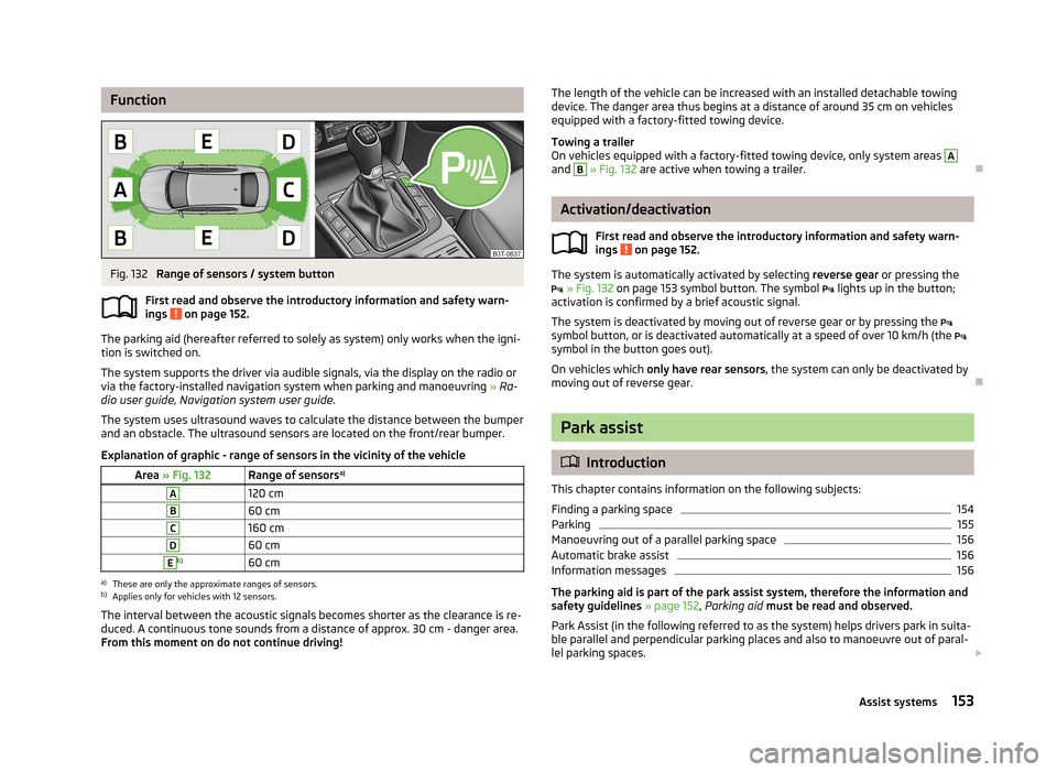
FunctionFig. 132
Range of sensors / system button
First read and observe the introductory information and safety warn- ings
on page 152.
The parking aid (hereafter referred to solely as system) only works when the igni- tion is switched on.
The system supports the driver via audible signals, via the display on the radio or via the factory-installed navigation system when parking and manoeuvring » Ra-
dio user guide, Navigation system user guide.
The system uses ultrasound waves to calculate the distance between the bumper
and an obstacle. The ultrasound sensors are located on the front/rear bumper.
Explanation of graphic - range of sensors in the vicinity of the vehicle
Area » Fig. 132Range of sensors a)A120 cmB60 cmC160 cmD60 cmEb)60 cma)
These are only the approximate ranges of sensors.
b)
Applies only for vehicles with 12 sensors.
The interval between the acoustic signals becomes shorter as the clearance is re-
duced. A continuous tone sounds from a distance of approx. 30 cm - danger area.
From this moment on do not continue driving!
The length of the vehicle can be increased with an installed detachable towing device. The danger area thus begins at a distance of around 35 cm on vehicles
equipped with a factory-fitted towing device.
Towing a trailer
On vehicles equipped with a factory-fitted towing device, only system areas A
and
B
» Fig. 132 are active when towing a trailer.
Activation/deactivation
First read and observe the introductory information and safety warn-
ings
on page 152.
The system is automatically activated by selecting reverse gear or pressing the
» Fig. 132 on page 153 symbol button. The symbol
lights up in the button;
activation is confirmed by a brief acoustic signal.
The system is deactivated by moving out of reverse gear or by pressing the
symbol button, or is deactivated automatically at a speed of over 10 km/h (the
symbol in the button goes out).
On vehicles which only have rear sensors , the system can only be deactivated by
moving out of reverse gear.
Park assist
Introduction
This chapter contains information on the following subjects:
Finding a parking space
154
Parking
155
Manoeuvring out of a parallel parking space
156
Automatic brake assist
156
Information messages
156
The parking aid is part of the park assist system, therefore the information and
safety guidelines » page 152, Parking aid must be read and observed.
Park Assist (in the following referred to as the system) helps drivers park in suita- ble parallel and perpendicular parking places and also to manoeuvre out of paral-lel parking spaces.
153Assist systems