trailer SKODA SUPERB 2013 2.G / (B6/3T) Owner's Manual
[x] Cancel search | Manufacturer: SKODA, Model Year: 2013, Model line: SUPERB, Model: SKODA SUPERB 2013 2.G / (B6/3T)Pages: 274, PDF Size: 17.31 MB
Page 6 of 274
Table of Contents
Materials defect liability and ŠKODA warranty for
new cars5
Mobility warranty and ŠKODA extended
warranty
6
Abbreviations
Using the system
Cockpit
9
Overview
8
Instruments and Indicator Lights
10
Instrument cluster
10
Warning Lights
14
Information system
23
Driver information system
23
Multifunction display (MFA)
25
MAXI DOT display
28
Service Interval Display
30
Unlocking and opening
32
Unlocking and locking
32
KESSY
37
Anti-theft alarm system
38
Luggage compartment lid
39
Electric boot lid (Superb Combi)
41
Electric power windows
44
Electric sliding/tilting roof
47
Panoramic sliding roof (Superb Combi)
48
Lights and visibility
51
Lights
51
Interior lights
57
Visibility
59Windscreen wipers and washers61Rear mirror63
Seats and useful equipment
66
Adjusting the seats
66
Seat features
70
Practical equipment
74
Luggage compartment
84
Removable light (Superb Combi)
90
Variable loading floor in the luggage
compartment (Estate)
92
Extending variable loading floor with integrated
aluminium rails and faseting elements (Superb Combi)
92
Net partition (Superb Combi)
95
Roof rack system
96
Air conditioning system
98
Heating, ventilation and cooling
98
Air conditioning system (manual air conditioningsystem)
100
Climatronic (automatic air conditioningsystem)
103
Auxiliary heating (auxiliary heating andventilation)
107
Communication and multimedia
110
General information
110
Universal telephone preinstallation GSM II
113
Universal telephone preinstallation GSM IIl
115
WLAN
119
Voice control
122
Multimedia
126
Driving
Starting-off and Driving
130
Steering
130
Starting and stopping the engine using the key
131
Starting and stopping the engine - KESSY
133Brakes137Manual gear changing and pedals138
Automatic transmission
139
Running in
142
Economical driving and environmental
sustainability
143
Avoiding damage to your vehicle
147
Driving abroad
148
Assist systems
150
Brake assist systems
150
Parking aid
152
Park assist
153
Cruise Control System
157
START-STOP
159
Fatigue detection (break recommendation)
161
Towing a trailer
162
Towing device
162
Trailer
165
Safety
Passive Safety
169
General information
169
Correct seated position
170
Seat belts
173
Using seat belts
173
Inertia reels and belt tensioners
176
Airbag system
178
Description of the airbag system
178
Airbag overview
179
Deactivating airbags
183
Transporting children safely
186
Child seat
186
Fastening systems
1883Table of Contents
Page 41 of 274
Fault in KESSY system
If there is a fault in the KESSY system, the following message will appear in the
display of the instrument cluster.
Keyless access system faulty.CHECK KEYLESS
Low voltage of the key battery
If the voltage of the battery in the remote control key is too low, the following
message appears in the display of the instrument cluster.
Change the key battery!
KEY BATTERY
Change the key battery » page 239!
Parking vehicle
First read and observe the introductory information given on page 37.
If the vehicle is not unlocked within 60 hours/ 90 hours, the sensors in the handleof the driver /front passenger's door are deactivated automatically » Fig. 14 on
page 34.
Activation after 60 hours
›
Unlock the driver's door using the sensor
2
» Fig. 14 on page 34.
›
Press the handle of the boot lid.
›
Unlock the vehicle using the symbol button
on the remote control key.
›
Unlocking the driver's door in an emergency » page 240.
Activation after 90 hours
›
Unlock the vehicle using the symbol button
on the remote control key.
›
Unlocking the driver's door in an emergency » page 240.
Anti-theft alarm system
Introduction
This chapter contains information on the following subjects:
Activating/deactivating
39
Interior monitor and towing protection
39
The anti-theft alarm system increases the level of protection against people
seeking to break into the vehicle. The system triggers audible and visual warning
signals if an attempt is made to break into the vehicle (hereafter referred to only
as alarm).
An alarm is triggered when the following monitored areas of the vehicle have a
fault.
› Bonnet.
› Boot lid.
› Doors.
› Ignition lock.
› Vehicle inclination
» page 39.
› Interior of car
» page 39.
› A drop in voltage of the on-board power supply.
› Socket of the factory-fitted towing device
» page 162, Towing a trailer .
An alarm is immediately triggered if either of the two battery terminals is discon-
nected while the anti-theft alarm system is activated.
The alarm is switched off by unlocking the vehicle or switching on the ignition.
CAUTION
Before leaving the vehicle, it must be checked that all of the doors and windows
including the sliding/tilting roof are locked in order to ensure the full functionality
of the anti-theft alarm system.
Note
The working life of the alarm siren is 5 years.
38Using the system
Page 45 of 274
Manual operation
Manually opening and closing the lid is only possible in exceptional cases. It must
be completed slowly and without sudden movements as close to the centre of
the lid as possible »
.
WARNING■
Ensure that the lock is properly engaged after closing the boot lid. Other-
wise, the boot lid might open suddenly while the vehicle is moving, even it
was locked – risk of accident!■
Never drive with the boot lid open or ajar, as otherwise exhaust gases may
get into the interior of the vehicle – risk of poisoning!
CAUTION
■ The movement of the lid can be stopped by applying an abrupt and quick force
against the lid.■
Do not try to close the lid manually during the electrical closing process. Dam-
age can occur to the system of the electric boot lid.
■
If the lid is closed manually, it must be ensured that when moving the lid into
the lock, pressure is applied to the centre edge of the lid above the ŠKODA logo. Handling the sides of the lid can damage the electric lid.
CAUTION
■ Before opening or closing the lid, check if there are any objects in the opening
or closing range which could obstruct the movement (e.g. a load on the roof rack
or on the trailer, etc.) – risk of causing damage to the lid!■
Ensure that there is at least 10 cm of clearance above the opened lid (e.g. dis-
tance from the garage ceiling). Otherwise, it may happen that the clearance
above the opened lid is no longer sufficient after relieving the vehicle of a load
(e.g. after unloading) – risk of causing damage to the lid.
■
In certain circumstances, if the lid is loaded (e.g by a thick layer of snow), the
opening process of the lid can be interrupted. Remove the load on the lid to re-
enable the electrical operation.
■
If the lid closes automatically (e.g. under load of snow), you will hear an inter-
mittent beep.
Operating descriptionFig. 23
Operation of the lid
Fig. 24
Lid operation/operating areas
First read and observe the introductory information and safety warn-
ings
on page 41.
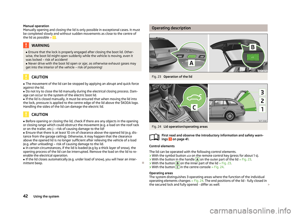
Control elements
The lid can be operated with the following control elements. › With the symbol button
on the remote control key (press for about 1 s).
› With the button in the handle
A
on the outer part of the lid
» Fig. 23.
› With the button
B
on the inner part of the lid
» Fig. 23.
› With the button
C
in the centre console
» Fig. 24.
Operating areas
The system distinguishes 3 operating areas where the function of the individual operating elements changes » Fig. 24. The end positions of the lid - fully closed in
the secured lock and fully opened - differ as well.
42Using the system
Page 46 of 274
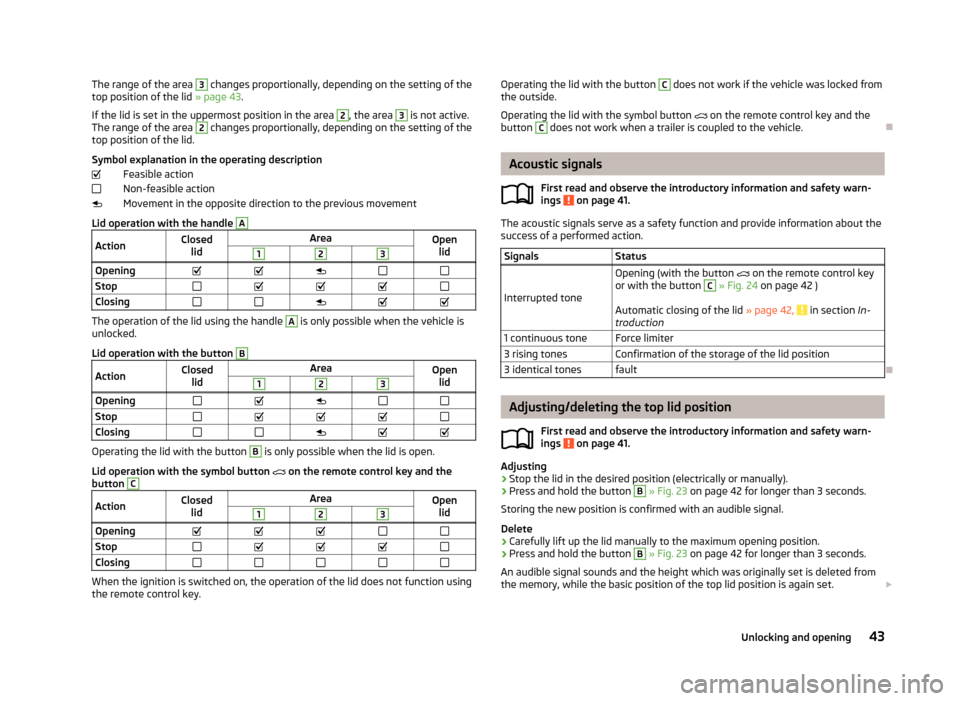
The range of the area 3 changes proportionally, depending on the setting of the
top position of the lid » page 43.
If the lid is set in the uppermost position in the area 2
, the area
3
is not active.
The range of the area
2
changes proportionally, depending on the setting of the
top position of the lid.
Symbol explanation in the operating description Feasible action
Non-feasible action
Movement in the opposite direction to the previous movement
Lid operation with the handle
AActionClosed lidAreaOpenlid123OpeningStopClosing
The operation of the lid using the handle
A
is only possible when the vehicle is
unlocked.
Lid operation with the button
BActionClosed lidAreaOpenlid123OpeningStopClosing
Operating the lid with the button
B
is only possible when the lid is open.
Lid operation with the symbol button
on the remote control key and the
button
CActionClosed lidAreaOpenlid123OpeningStopClosing
When the ignition is switched on, the operation of the lid does not function usingthe remote control key.
Operating the lid with the button C does not work if the vehicle was locked from
the outside.
Operating the lid with the symbol button on the remote control key and the
button C
does not work when a trailer is coupled to the vehicle.
Acoustic signals
First read and observe the introductory information and safety warn-ings
on page 41.
The acoustic signals serve as a safety function and provide information about the
success of a performed action.
SignalsStatus
Interrupted tone
Opening (with the button on the remote control key
or with the button C
» Fig. 24 on page 42 )
Automatic closing of the lid » page 42,
in section In-
troduction
1 continuous toneForce limiter3 rising tonesConfirmation of the storage of the lid position3 identical tonesfault
Adjusting/deleting the top lid position
First read and observe the introductory information and safety warn-ings
on page 41.
Adjusting
›
Stop the lid in the desired position (electrically or manually).
›
Press and hold the button
B
» Fig. 23 on page 42 for longer than 3 seconds.
Storing the new position is confirmed with an audible signal.
Delete
›
Carefully lift up the lid manually to the maximum opening position.
›
Press and hold the button
B
» Fig. 23 on page 42 for longer than 3 seconds.
An audible signal sounds and the height which was originally set is deleted from
the memory, while the basic position of the top lid position is again set.
43Unlocking and opening
Page 58 of 274
Fog lightsFig. 33
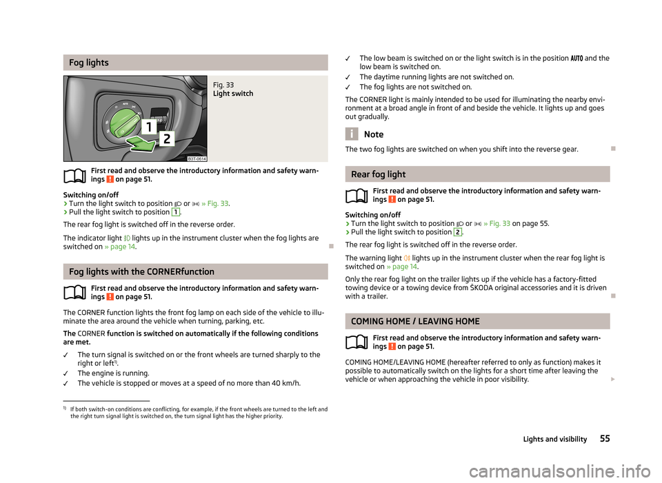
Light switch
First read and observe the introductory information and safety warn-
ings on page 51.
Switching on/off
›
Turn the light switch to position
or
» Fig. 33 .
›
Pull the light switch to position
1
.
The rear fog light is switched off in the reverse order.
The indicator light
lights up in the instrument cluster when the fog lights are
switched on » page 14.
Fog lights with the CORNERfunction
First read and observe the introductory information and safety warn-ings
on page 51.
The CORNER function lights the front fog lamp on each side of the vehicle to illu-
minate the area around the vehicle when turning, parking, etc.
The CORNER function is switched on automatically if the following conditions
are met.
The turn signal is switched on or the front wheels are turned sharply to the
right or left 1)
.
The engine is running.
The vehicle is stopped or moves at a speed of no more than 40 km/h.
The low beam is switched on or the light switch is in the position and the
low beam is switched on.
The daytime running lights are not switched on. The fog lights are not switched on.
The CORNER light is mainly intended to be used for illuminating the nearby envi-
ronment at a broad angle in front of and beside the vehicle. It lights up and goes out gradually.
Note
The two fog lights are switched on when you shift into the reverse gear.
Rear fog light
First read and observe the introductory information and safety warn-
ings
on page 51.
Switching on/off
›
Turn the light switch to position
or
» Fig. 33 on page 55.
›
Pull the light switch to position
2
.
The rear fog light is switched off in the reverse order.
The warning light
lights up in the instrument cluster when the rear fog light is
switched on » page 14.
Only the rear fog light on the trailer lights up if the vehicle has a factory-fitted
towing device or a towing device from ŠKODA original accessories and it is driven
with a trailer.
COMING HOME / LEAVING HOME
First read and observe the introductory information and safety warn-ings
on page 51.
COMING HOME/LEAVING HOME (hereafter referred to only as function) makes it
possible to automatically switch on the lights for a short time after leaving the
vehicle or when approaching the vehicle in poor visibility.
1)
If both switch-on conditions are conflicting, for example, if the front wheels are turned to the left and
the right turn signal light is switched on, the turn signal light has the higher priority.
55Lights and visibility
Page 146 of 274

Up to 1 000 kilometres›Do not drive faster than 3/4 of the maximum speed of the gear in use, i.e. 3/4 of
the maximum permissible engine speed.›
No full throttle.
›
Avoid high engine speeds.
›
Do not tow a trailer.
From 1 000 up to 1 500 kilometres
Gradually increase the power output of the engine up to the full speed of the
gear engaged, i.e. up to the maximum permissible engine speed.
The red scale of the rev counter indicates the range in which the system beginsto limit the engine speed.
During the first operating hours the engine has higher internal friction than later until all of the moving parts have harmonized. The driving style which you adopt
during the first approx.1 500 kilometres plays a decisive part in the success of
running in your car.
Never drive at unnecessarily high engine speeds even after the running-in period.
On vehicles fitted with a manual gearbox, at the very latest shift up into the next
gear when the red area is reached. Observe the recommended gear » page 24,
Gear recommendation . Very high engine speeds when accelerating (accelerator)
are automatically restricted »
.
In vehicles with manual transmission, do not drive at unnecessarily low engine
speeds. Shift down a gear when the engine is no longer running smoothly. Ob-
serve the recommended gear » page 24, Gear recommendation .
CAUTION
■
The engine is not protected from excessive engine revs caused by shifting
down at the wrong time. This can result in a sudden increase in revs beyond the
permissible maximum rpm, thereby causing engine damage.■
Never rev up a cold engine when the vehicle is stationary or when driving in in-
dividual gears.
For the sake of the environment
Do not drive at unnecessarily high engine speeds. Shifting up sooner helps save
fuel, reduces engine noise and protects the environment.
New tyres
First read and observe the introductory information given on page 142.
New tyres must firstly be “run in”, as they do not offer optimal grip at first. There-fore, drive especially carefully for the first 500 km or so.
New brake pads
First read and observe the introductory information given on page 142.
New brake pads do not initially provide optimal braking performance. They firstneed to be “run in”. Therefore, drive especially carefully for the first 200 km or so.
Economical driving and environmental sustainability
Introduction
This chapter contains information on the following subjects:
Looking ahead
144
Economical gear changing
144
Avoiding full throttle
145
Reducing idling
145
Avoiding short distances
145
Checking tyre inflation pressure
145
Avoiding unnecessary ballast
146
Regular maintenance
146
Saving electrical energy
146
Environmental compatibility
146
The technical requirements for low fuel usage and economic efficiency of the ve-
hicle have already been built into the vehicle at the works. ŠKODA places a partic-
ular emphasis on minimising negative effects on the environment.
It is necessary to take note of the guidelines given in this chapter in order tomake best use of these characteristics and to maintain their effectiveness.
143Starting-off and Driving
Page 153 of 274
Assist systems
Brake assist systems
Introduction
This chapter contains information on the following subjects:
Electronic Stability Control (ESC)
150
Antilock Braking System (ABS)
151
Traction Control System (TCS)
151
Electronic Differential Lock (EDL)
151
Driver Steering Recommendation (DSR)
151
Hydraulic Brake Assist (HBA)
151
Hill Hold Control (HHC)
152WARNING■ A lack of fuel can cause irregular engine running or cause the engine to shut
down. The brake assist systems would then fail to function – risk of accident!■
Adjust the speed and driving style to the current visibility, weather, road and
traffic conditions. The increased safety provided by the brake assist systems
must not tempt you to take safety risks – risk of accident!
■
In the event of an ABS fault, visit a specialist garage immediately. Adjust
your style of driving according to the damage to the ABS, as you will not know
the exact extent of the damage or the extent to which this is limiting the
braking efficiency.
CAUTION
■ All four wheels must be fitted with the same tyres approved by the manufactur-
er to ensure the brake assist systems operate correctly.■
Changes to the vehicle (e.g. to the engine, brakes, chassis) can influence the
functionality of the brake assist systems » page 193, Services, modifications, and
technical alterations .
■
If a fault occurs in the ABS system, the ESC, ASR and EDL will also not work. An
ABS fault is indicated by the warning light » page 19 .
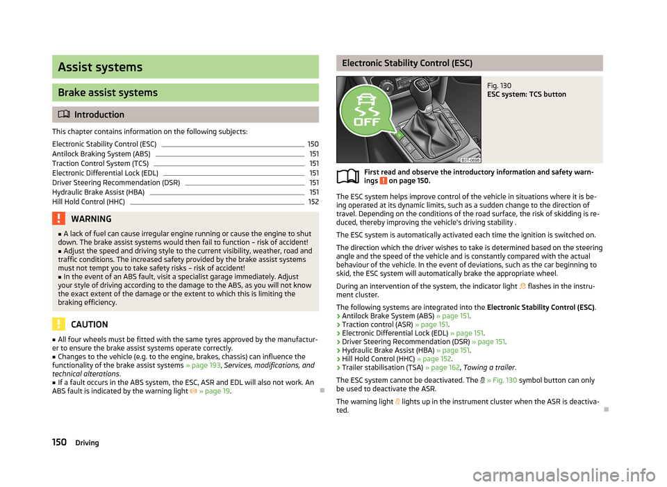
Electronic Stability Control (ESC)Fig. 130
ESC system: TCS button
First read and observe the introductory information and safety warn-
ings on page 150.
The ESC system helps improve control of the vehicle in situations where it is be-
ing operated at its dynamic limits, such as a sudden change to the direction of
travel. Depending on the conditions of the road surface, the risk of skidding is re-
duced, thereby improving the vehicle's driving stability .
The ESC system is automatically activated each time the ignition is switched on.The direction which the driver wishes to take is determined based on the steering angle and the speed of the vehicle and is constantly compared with the actualbehaviour of the vehicle. In the event of deviations, such as the car beginning to
skid, the ESC system will automatically brake the appropriate wheel.
During an intervention of the system, the indicator light
flashes in the instru-
ment cluster.
The following systems are integrated into the Electronic Stability Control (ESC).
› Antilock Brake System (ABS)
» page 151.
› Traction control (ASR)
» page 151.
› Electronic Differential Lock (EDL)
» page 151.
› Driver Steering Recommendation (DSR)
» page 151.
› Hydraulic Brake Assist (HBA)
» page 151.
› Hill Hold Control (HHC)
» page 152.
› Trailer stabilisation (TSA)
» page 162, Towing a trailer .
The ESC system cannot be deactivated. The
» Fig. 130 symbol button can only
be used to deactivate the ASR.
The warning light lights up in the instrument cluster when the ASR is deactiva-
ted.
150Driving
Page 155 of 274
The HBA is activated by very quick operation of the brake pedal. In order to ach-
ieve the shortest possible braking distance, the brake pedal must be applied firm-
ly until the vehicle has come to a standstill.
The HBA function is automatically deactivated when the brake pedal is released.
The ABS is activated faster and more effectively with the intervention of the HBA.
Hill Hold Control (HHC)
First read and observe the introductory information and safety warn-ings
on page 150.
When driving on slopes, HHC allows you to move your foot from the brake pedal
to the accelerator pedal without having to use the handbrake.
The system holds the brake pressure produced by the activation of the brakepedal for approx. 2 seconds after the brake pedal is released.
The brake pressure drops gradually the more you operate the accelerator pedal. Ifthe vehicle does not start off within 2 seconds, it starts to roll back.
The HHC is active on slops of >5 % if the driver door is closed. HHC is only everactive on slopes when in forward or reverse start off. When driving downhill, it is
inactive.
Parking aid
Introduction
This chapter contains information on the following subjects:
Function
153
Activation/deactivation
153WARNING■ The parking aid is not a substitute for the driver paying proper attention and
it is always the driver's responsibility to take care when reversing the vehicle
or carrying out similar manoeuvres. Pay particular attention to small children
and animals as they may not be recognised by the system sensors.■
Before reversing, you should make sure that there are no small obstacles,
such as rocks, thin posts, trailer drawbars etc. in front or behind your vehicle.
Such obstacles may not be recognised by the system sensors.
■
Under certain circumstances, surfaces of certain objects and types of cloth-
ing cannot reflect the system signals. Thus, these objects or people who wear such clothing are not recognised by the System sensors.
■
External sound sources can have a detrimental effect on the system. Under
adverse conditions, this may cause objects or people to not be recognised by
the system.
CAUTION
■ If a warning signal sounds for about 3 seconds after activating the system and
there is no obstacle close to your car, this indicates a system fault. The fault is
also indicated by the symbol flashing in the » Fig. 132 on page 153 button.
Seek help from a specialist garage.■
The sensors must be kept clean (free of ice, etc.) to enable the system to oper-
ate properly.
■
Additionally installed modules such as bicycle carriers can impair the function of
the parking aid.
Note
■ The signal tones for front obstacle recognition are factory-set to be higher than
for rear obstacle recognition.■
The sound of the park-assist can be adjusted via the MAXI DOT display in the
Wizards menu option » page 29.
■
If the system is activated and the selector lever of the automatic gearbox is in
position P (the vehicle cannot move), the warning tone is interrupted and no ob-
stacles are displayed.
152Driving
Page 156 of 274
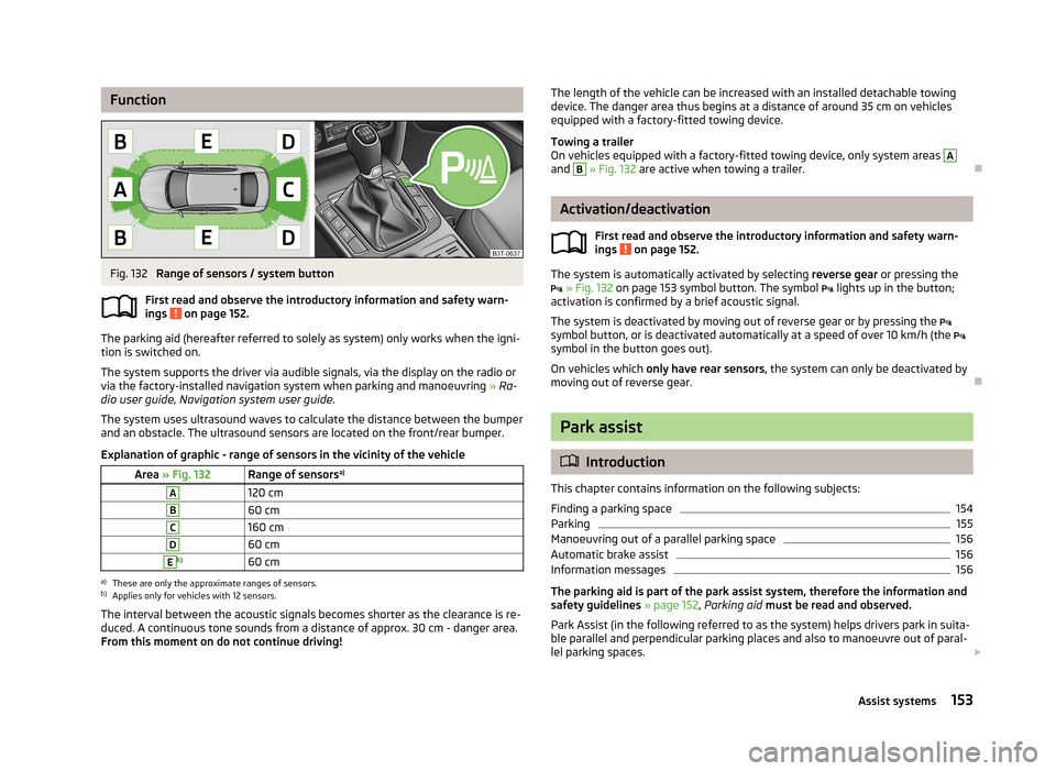
FunctionFig. 132
Range of sensors / system button
First read and observe the introductory information and safety warn- ings
on page 152.
The parking aid (hereafter referred to solely as system) only works when the igni- tion is switched on.
The system supports the driver via audible signals, via the display on the radio or via the factory-installed navigation system when parking and manoeuvring » Ra-
dio user guide, Navigation system user guide.
The system uses ultrasound waves to calculate the distance between the bumper
and an obstacle. The ultrasound sensors are located on the front/rear bumper.
Explanation of graphic - range of sensors in the vicinity of the vehicle
Area » Fig. 132Range of sensors a)A120 cmB60 cmC160 cmD60 cmEb)60 cma)
These are only the approximate ranges of sensors.
b)
Applies only for vehicles with 12 sensors.
The interval between the acoustic signals becomes shorter as the clearance is re-
duced. A continuous tone sounds from a distance of approx. 30 cm - danger area.
From this moment on do not continue driving!
The length of the vehicle can be increased with an installed detachable towing device. The danger area thus begins at a distance of around 35 cm on vehicles
equipped with a factory-fitted towing device.
Towing a trailer
On vehicles equipped with a factory-fitted towing device, only system areas A
and
B
» Fig. 132 are active when towing a trailer.
Activation/deactivation
First read and observe the introductory information and safety warn-
ings
on page 152.
The system is automatically activated by selecting reverse gear or pressing the
» Fig. 132 on page 153 symbol button. The symbol
lights up in the button;
activation is confirmed by a brief acoustic signal.
The system is deactivated by moving out of reverse gear or by pressing the
symbol button, or is deactivated automatically at a speed of over 10 km/h (the
symbol in the button goes out).
On vehicles which only have rear sensors , the system can only be deactivated by
moving out of reverse gear.
Park assist
Introduction
This chapter contains information on the following subjects:
Finding a parking space
154
Parking
155
Manoeuvring out of a parallel parking space
156
Automatic brake assist
156
Information messages
156
The parking aid is part of the park assist system, therefore the information and
safety guidelines » page 152, Parking aid must be read and observed.
Park Assist (in the following referred to as the system) helps drivers park in suita- ble parallel and perpendicular parking places and also to manoeuvre out of paral-lel parking spaces.
153Assist systems
Page 160 of 274
The parking procedure was ended because TCS was deactivated during the park-
ing procedure.
Trailer: Park Assist stopped.
The parking procedure cannot be carried out because a trailer is hitched. Time limit exceeded. Take over steering!
The parking procedure was ended because the time limit of 6 minutes was passed.
Park Assist currently not available.
The system cannot be activated because a fault exists on the vehicle. Seek help
from a specialist garage.
Park Assist stopped. System currently not available.
The parking procedure was ended because a fault exists on the vehicle. Seek help
from a specialist garage.
Park Assist faulty. Workshop!
The parking procedure is not possible because a fault exists in the system. Seek help from a specialist garage.
Park Assist stopped. Take over steering!
Assume control of the steering. Complete the parking procedure without using the system.
ASR intervention. Take over steering!
The parking procedure is terminated by a TCS intervention.
PARK ASSIST Turn on turn signal and select reverse gear
The prerequisites for manoeuvring out of a parking space using the system have
been met. Switch on the turn signals and shift into reverse.
Please take over steering and drive on.
The manoeuvring procedure out of a parallel parking space has ended. Assume control of the steering.
Automatic space departure not possible. Space too small.
The manoeuvring procedure using the system is not possible. The parking gap is
too small.
Park Assist: Brake interv. Speed too high.The driving speed during the parking procedure was too high - automatic brake
assist is initiated.
Cruise Control System
Introduction
This chapter contains information on the following subjects:
Activating/deactivating
158
Storing and maintaining speed
158
Changing the stored speed
158
Switching off temporarily
158
The Cruise Control System (CCS) maintains a set speed, more than 25 km/h, with-
out you having to actuate the accelerator pedal.
This is only possible within the range which is permitted by the power output and
braking power of the engine.
The warning light
illuminates in the instrument cluster when the cruise control
system is switched on.
WARNING■ For safety reasons, the cruise control system must not be used in dense
traffic or on unfavourable road surfaces (such as icy roads, slippery roads,
loose gravel) – risk of accident!■
The saved speed may only be resumed if it is not too high for the current
traffic conditions.
■
Always deactivate the cruise control system after use to prevent the system
being switched on unintentionally.
CAUTION
■ The cruise control system is not able to maintain a constant speed when driving
in areas with steeper gradients. The weight of the vehicle increases the speed at which it travels. In such cases, select a lower gear or brake the vehicle using the
footbrake.■
The cruise control system cannot be activated when first gear or reverse gear is
selected (vehicles with manual transmission).
157Assist systems