steering SKODA SUPERB 2014 2.G / (B6/3T) Service Manual
[x] Cancel search | Manufacturer: SKODA, Model Year: 2014, Model line: SUPERB, Model: SKODA SUPERB 2014 2.G / (B6/3T)Pages: 246, PDF Size: 17.16 MB
Page 163 of 246
Automatic engine shutdown takes place, segment display shows START STOP
ACTIVE or a check mark appears in the MAXI DOT display » Fig. 151 on
page 160 .
Automatic engine start›
Release the brake pedal.
The automatic start procedure takes place again.
Further information on automatic transmission
The automatic engine shut down takes place when the selector lever is in po-
sitions P, D , S and N and in Tiptronic mode.
When the selector lever is in position P, the engine remains shut down even
after you release the brake pedal. The engine starts automatically by pressing
the gas pedal or by moving the selector lever into a different mode and releas-
ing the brake pedal.
If the engine is off due to the automatic and the selector lever is put to the R
position then the automatic starts the engine.
If the gear selector is moved from position R to the position D, S or N, the vehi-
cle must reach a speed of more than 10 km / h before the automatic engine
shutdown starts.
There is no automatic engine shutdown when the system detects a vehicle
moving due to a large steering angle.
No automatic engine shutdown takes place when the vehicle is moving at low
speed (e.g. during a traffic jam or when tuning) and remains stationary after
pressing the brake pedal lightly. Automatic engine shutdown takes place if you
press the brake pedal down with more force.
System related automatic start-up
Read and observe
on page 159 first.
When the engine is off, the system can automatically start the engine before
the desired journey continues. Some possible reasons for this are:
› The vehicle begins to roll, e.g. on a slope.
› The brake pedal has been actuated several times.
› The current consumption is too high.
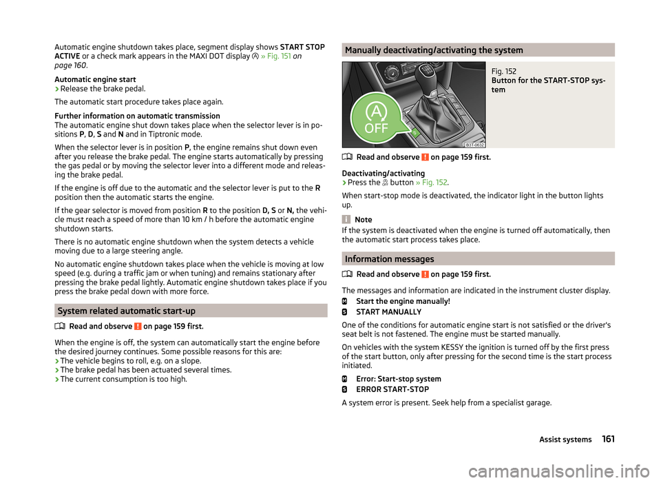
Manually deactivating/activating the systemFig. 152
Button for the START-STOP sys-
tem
Read and observe on page 159 first.
Deactivating/activating
›
Press the button
» Fig. 152 .
When start-stop mode is deactivated, the indicator light in the button lights
up.
Note
If the system is deactivated when the engine is turned off automatically, then
the automatic start process takes place.
Information messages
Read and observe
on page 159 first.
The messages and information are indicated in the instrument cluster display. Start the engine manually!
START MANUALLY
One of the conditions for automatic engine start is not satisfied or the driver's
seat belt is not fastened. The engine must be started manually.
On vehicles with the system KESSY the ignition is turned off by the first press
of the start button, only after pressing for the second time is the start process
initiated.
Error: Start-stop system
ERROR START-STOP
A system error is present. Seek help from a specialist garage.
161Assist systems
Page 164 of 246
Fatigue detection (break recommendation)
Introduction
This chapter contains information on the following subjects:
Function
162
Information messages
162WARNING■ For the driving ability is always the driver's responsibility. Never drive if
you feel tired.■
The system may not detect all cases where a break is needed.
■
Therefore, take regular, sufficient breaks during long trips.
■
There will be no system warning during the so-called micro-sleep.
Note
■ In some situations, the system may evaluate the driving incorrectly and thus
mistakenly recommend a break (e.g. sporty driving, adverse weather condi-
tions or poor road conditions).■
The fatigue detection system is designed primarily for motorway driving.
Function
Read and observe
on page 162 first.
The fatigue detection system advises the driver on the basis of informationabout the steering behaviour, to take a break from driving. The system recom-
mends a break at speeds of 65-200 km/h.
After the ignition has been switched on, the system evaluates the steering be-
haviour for 15 minutes. This baseline analysis is constantly compared with the
current steering behaviour.
If the system detects deviations from normal steering behaviour due to possi-
ble fatigue of the driver, it recommends to take a break from driving.
The system deletes the stored baseline analysis if one of the following con-
ditions is met.
› The vehicle is stopped and the ignition switched off.
› The vehicle is stopped, the seat belt removed and the driver's door opened.
› The vehicle is stopped for more than 15 minutes.
If none of these conditions are met or if the driving style is not changed, the
system recommends a driving break again after 15 minutes.
Activation/deactivation
The system can be activated/deactivated via the MAXI DOT display in the Wiz-
ards menu option » page 44.
Information messages
Read and observe
on page 162 first.
In MAXI DOT display the icon appears for a few seconds and the following
message.
Fatigue detected. Take a break!
An audible signal is also emitted.
162Driving
Page 170 of 246
Note■After coupling the trailer and connecting the power socket, check that the
rear lights on the trailer are working correctly.■
If there is an error in the trailer lighting, check the fuses in the fuse box in
the dash panel » page 216.
■
Contact between the breakaway cable and the safety eyelet can result in
mechanical wear on the surface protection of the eyelet. Such wear does not
impair the functioning of the safety eyelet and does not constitute a fault. It is
excluded from the warranty coverage.
■
If you tow a trailer frequently, you should also have your vehicle inspected
between service intervals.
■
The handbrake on the towing vehicle must be applied when coupling and un-
coupling the trailer.
Trailer stabilisation (TSA)
Read and observe
on page 166 first.
The trailer stabilisation is an extension of the stabilisation control that works
in conjunction with the counter-steering assistance to reduce the amount the
trailer "sways".
After turning on the ignition, the ESC indicator light in the instrument clus-
ter lights up for about 2 seconds longer than the ABS indicator light.
Function requirements for trailer stabilisation. The coupling device was factory-fitted or purchased from the ŠKODA Origi-
nal Accessories.
The ESC is active. (Warning lights or
do
not illuminate in the instru-
ment cluster).
The trailer is electrically connected to the towing vehicle via the trailer
socket.
The speed is higher than approx. 60 km/h.
The trailer has a rigid drawbar.
WARNINGThe increased safety offered by the trailer stabilisation must not tempt you to take greater risks than otherwise.CAUTION■ The trailer stabilisation need not be able to correctly detect all of driving sit-
uations.■
Light trailers that sway are not always detected and therefore stabilised ac-
cordingly by the trailer stabilisation.
■
Release the pressure on the accelerator pedal if the system is being regula-
ted.
■
Avoid abrupt and sudden driving/braking manoeuvres.
Note
The trailer stabilisation works for both braked and unbraked trailers.
Anti-theft alarm system
Read and observe
on page 166 first.
When the vehicle is locked, the alarm is activated when the electrical connec-
tion to the trailer is interrupted.
Always switch off the anti-theft alarm system before a trailer is coupled or un-
coupled » page 54 .
Conditions for including a trailer in the anti-theft alarm system. The vehicle is factory-fitted with an anti-theft alarm system and towing
device.
The trailer is electrically connected to the towing vehicle via the trailer
socket.
The electrical system of the vehicle and trailer is functional.
The vehicle is locked with the vehicle key and the anti-theft alarm system
is activated.
Note
For technical reasons, trailers with rear LED lights cannot be connected to the
anti-theft alarm system.168Driving
Page 173 of 246
ŠKODA service partners are liable for any ŠKODA Genuine Part defects for aperiod of 2 years after installation or delivery in accordance with the materials
defect liability, provided that nothing else was agreed in the purchase contract
or in any other agreements. You should keep the approved warranty certificate
and the bill for these components for this period of time, so that commence-
ment of the term may be verified.
In addition, ŠKODA Service Partners also stock a range of suitable car care
products as well as those parts which are subject to natural wear-and-tear,
such as tyres, batteries, bulbs and wiper blades.
Note
The accessories authorized by the company ŠKODA AUTO a.s. will be offered
by the ŠKODA partners in all countries where the company ŠKODA AUTO a.s.
has a sales and service network. This will usually be in the form of a printed
catalogue of Original ŠKODA Accessories, in the form of separate printed bro-
chures or in the form of offers for ŠKODA Genuine Accessories on the ŠKODA
partner web pages.
Spoiler
Read and observe
on page 169 first.
If your new vehicle is fitted with a spoiler on the front bumper in combination
with the spoiler on the luggage compartment lid, the following instructions
must be adhered to.
› For safety reasons, the vehicle must only be fitted with a spoiler on the front
bumper in combination with the associated spoiler on the luggage compart-
ment lid.
› This kind of spoiler cannot be left on the front bumper either on its own, in
combination with another spoiler not on the luggage compartment lid or in
combination with an unsuitable spoiler on the luggage compartment lid.
› We recommend that you consult the ŠKODA Service Partner for any repairs
to or replacement, addition or removal of spoilers.
WARNINGIf work on your vehicle's spoilers is not carried out properly, this can lead to
operational faults - risk of accident and serious injuries.Airbags
Read and observe
on page 169 first.
The system components of the airbag system can be situated in the front
bumper, doors, front seats, roof lining or body.
WARNINGAny work on the airbag system including the installation and removal of
system components due to other repair work (e.g. removal of the steering
wheel) must only be carried out by a specialist garage.■
Modifications, repairs and technical alterations that have been carried out
unprofessionally can cause damage and operational faults, and can also se-
riously impair the effectiveness of the airbag system – risk of accident and
fatal injury!
■
The airbag system must then be replaced if the airbag has been deployed.
Airbag modules cannot be repaired.
WARNINGInformation on the use of the airbag system■It is prohibited to manipulate individual parts of the airbag system, as this
might result in the airbag being deployed.■
Never install any airbag parts into the vehicle that have been removed
from old cars or have been recycled.
■
Never install damaged airbag parts in the vehicle. The airbags may then
not be deployed properly or even at all in the event of an accident.
■
No modifications of any kind must be made to parts of the airbag system.
WARNING■ A change to the vehicle's wheel suspension, including the use of non-ap-
proved wheels and tire combinations, can alter the functioning of the air-
bag system - risk of accident and fatal injury!■
Never make any changes to the front bumper or the bodywork.
171Car care
Page 178 of 246
Cavity protectionRead and observe
and on page 173 first.
All the cavities of your vehicle which are at risk from corrosion are protected
for life by a layer of protective wax applied in the factory.
This wax protection does not need to be inspected or re-applied.
If any small amount of wax flow out of the cavities at high temperatures, these
must be removed with a plastic scraper and the stains cleaned using a petrole-
um cleaner.
WARNINGSafety regulations should be observed when using petroleum cleaner to re-
move wax – risk of fire!
Wheels
Read and observe
and on page 173 first.
Wheel rims
Also thoroughly wash the wheel rims when washing the vehicle on a regular
basis.
Regularly remove salt and brake abrasion, otherwise the rim material will be
corroded.
Damage to the paint layer on the wheel rims must be touched up immediately.
Light alloy wheels
After washing thoroughly and treat the wheel rims with a protective product
for light alloy wheels. Products which cause abrasion must not be used to
treat the wheel rims.
CAUTION
Severe layers of dirt on the wheels can also result in wheel imbalance. This
may show itself in the form of a wheel vibration which is transmitted to the
steering wheel which, in certain circumstances, can cause premature wear of
the steering. This means it is necessary to remove the dirt.Underbody protection
Read and observe
and on page 173 first.
The underside of your vehicle is protected for life against chemical and me-
chanical influences.
It is not possible to guarantee that the protective coating will not suffer any
damage as the vehicle is driven.
We recommend having the protective coating underneath the vehicle and the
chassis checked — preferably before the beginning of winter and at the end of
winter.
WARNINGNever use additional underbody protection or anti-corrosion agents for ex-
haust pipes, catalytic converters, diesel particle filters or heat shields.
When the engine reaches its operating temperature, these substances may ignite - risk of fire!
Taking care of the interior
Introduction
This chapter contains information on the following subjects:
Natural leather
177
Artificial leather, cloths and Alcantara ®
178
Seat covers
178
Seat belts
178
Regular and proper care help to retain the efficiency and
value of your vehicle.
We recommend using vehicle care products from ŠKODA Original Accessories.
These are available from ŠKODA Partners. The usage instructions on the pack-
age must be observed.
WARNING■ Vehicle care products may be harmful to your health if not used according
to the instructions.■
Always keep the vehicle care products safe from people who are not com-
pletely independent, e.g. children - there is a danger of poisoning!
176General Maintenance
Page 179 of 246
CAUTION■Be sure to check clothing for colourfastness to avoid any damage or visible
stains on the material (leather), panels and textiles.■
Remove fresh stains such as those from ball-point pens, ink, lipstick, shoe
polish, etc., from the material (leather), panels and textiles as quickly as possi-
ble.
■
Air fresheners and scents can be hazardous to heath when the temperature
inside the vehicle is high.
■
Do not attach scents or air fresheners to the dash panel – there is a risk of
damage to the dash panel.
■
Do not stick any stickers on the inside of the rear windows, the rear side win-
dows and in the vicinity of the heating elements on the windscreen or near the
window aerial. These may get damaged.
■
Do not clean the roof panelling with a brush – risk of damage to the surface
of the panelling.
■
Cleaner that contain solvents can damage the material being cleaned.
■
Apply only a small amount of the cleaning and care product.
For the sake of the environment
Used cans of vehicle care product represent hazardous waste that is harmful
to the environment. These must be disposed of in accordance with national
legislation.
Note
Because of the special tools and knowledge required, and to avoid any poten-
tial problems with the cleaning and care of the interior of your vehicle, we rec-
ommend that cleaning and care of the interior of your vehicle be carried out by
a ŠKODA Service Partner.
Natural leather
Read and observe
and on page 176 first.
Leather is a natural material with specific properties, and requires regular
cleaning and maintenance.
The leather should be cleaned on a regular basis depending on the amount of
wear-and-tear.
Dust and dirt in the pores and folds act as abrasive materials. This leads to se-
vere corrosion and the premature brittleness of the leather surface.
We recommend that you remove dust regularly and at short intervals using a
cloth or vacuum cleaner.
Clean soiled leather surfaces with a water-dampened cotton or woollen cloth
and then dry with a clean, dry cloth »
.
Clean severely soiled areas with a cloth soaked in a mild soap solution (2 ta-
blespoons of neutral soap to 1 litre of water).
To remove stains , use a cleaning agent specially designed for this purpose.
Treat the leather regularly and at suitable intervals using a suitable leather
care product.
CAUTION
■ Ensure that no part of the leather is soaked through during cleaning and that
no water gets into the seams. Otherwise, the leather could become brittle or
cracked.■
Avoid leaving the vehicle for lengthy periods in bright sunlight to avoid the
leather from bleaching. If the vehicle is parked in the open for lengthy periods,
protect the leather from direct sunlight by covering it.
■
Sharp-edged objects on items of clothing such as zip fasteners, rivets, sharp-
edged belts, jewellery and pendants may leave permanent scratches or signs
of rubbing on the surface. Such damage cannot be subsequently recognised as
a justified complaint.
■
The use of a mechanical steering wheel lock may damage the leather surface
of the steering wheel.
■
Use a care cream with light blocker and impregnation effect on a regular ba-
sis and each time after cleaning. The cream nourishes the leather, allows it to
breathe and keeps it supple and also provides moisture. It also creates surface
protection.
■
Some clothing materials, e.g. dark denim, do not have sufficient colour fast-
ness. This can cause damage or clearly visible discolouration to seat covers,
even when used correctly. This applies particularly to light-coloured seat cov-
ers. This does not relate to a fault in the seat cover, but rather to poor colour
fastness of the clothing textiles.
Note
When using the vehicle, minor visible changes may occur to the leather parts
of the covers (e.g. wrinkles or creases) as a result of the stress applied to the
covers.177Car care
Page 197 of 246

Fig. 169
Replacing wheels
Read and observe and on page 193 first.
The service life of tyres depends on the inflation pressure, driving style and
other circumstances. Following the advice below can extend the service life of
your tyres.
Tyre pressure
Check the tyre pressure, including that of the spare wheel, at least once a
month and also before setting off on a long journey.
The tyre pressures for tyres are shown on the inside of the fuel filler
flap » Fig. 168 –
.
The tyre pressure should be at the highest pressure specified for your vehicle
at all times.
Always check the inflation pressure when the tyres are cold. Do not reduce the
higher pressure on warm tyres.
With greater additional load, adjust the tyre inflation pressure accordingly.
Driving style
Fast cornering, sharp acceleration and braking increase the wear of your tyres.
Balancing wheels
The wheels of a new vehicle are balanced. When driving, however, there are a
range of factors that may result in an imbalance. This may become apparent by
a “vibration” in the steering.
Have the wheels rebalanced after replacing the tyres.
Wheel alignment errors
Incorrect wheel alignment at the front or rear leads to excess wear of the
tyres.
Tyre damage
Drive over kerbs and other such obstacles slowly and at right angles wherever
possible in order to avoid damage to tyres and wheel trims.
We recommend checking your tyres and wheel rims for damage (punctures,
cuts, splits and bulges, etc.) on a regular basis. Remove foreign bodies (e.g.
small stones) from the tyre tread immediately.
Replacing wheels
If significantly greater wear is present on the front tyres, we recommend
swapping the front wheels with the rear wheels as shown in the dia-
gram » Fig. 169 . You will then obtain approximately the same life for all the
tyres.
We recommend that you swap the tyres every 10,000 km in order to achieve
even wear on all tyres and to ensure optimal service life for the tyres.
Storing tyres
Identify disassembled tyres so that the previous direction of rotation can be
maintained if the tyres are reassembled.
Always store wheels or tyres in a cool, dry place that is as dark as possible.
Tyres which are not fixed to a wheel trim should be stored upright.
Wear indicators
The base of the tread of the tyres has 1.6 mm high wear indicators installed.
These wear indicators are arranged evenly spaced around the circumference of
the tyre a number of times depending on the make » Fig. 168 -
. Markings on
the walls of the tyres through the letters “TWI”, triangular symbols or other
symbols identify the position of the wear indicators.
Tyre age
Tyres age and lose their original characteristics, even if they are not being
used. Therefore, we recommend not using summer or winter tyres older than
6 or 4 years old respectively.
New tyres
Read and observe
and on page 193 first.
Only use radial tyres of the same type, size (rolling circumference) and tread
pattern on one axle on all four wheels.
The tyre/wheel combinations which are approved for your vehicle are indica-
ted in your vehicle documents.
195Wheels
Page 199 of 246
›Switch on the ignition.›Press the
» Fig. 170 symbol button for longer than 2 seconds.
If the warning light
in the instrument cluster lights up and does not go out
after the system configuration, this indicates a system fault.
If the warning light
in the instrument cluster flashes, there is a system fault.
Tyre pressure indicator
The warning light
in the instrument cluster lights up when any of the fol-
lowing conditions are met.
› The tyre inflation pressure is low.
› The structure of the tyre is damaged.
› The vehicle is loaded on one side.
› The wheels of one axle are loaded more heavily (e.g. when towing a trailer or
when driving uphill or downhill).
› Snow chains are mounted.
› The spare wheel is mounted.
› One wheel per axle was changed.WARNING■
When the warning light in the instrument cluster lights up, immediate-
ly reduce the speed and avoid sudden steering and brake manoeuvres.
Stop the vehicle as soon as possible and inspect the tyres and their infla-
tion pressure.■
Under certain circumstances (e.g. sporty style of driving, wintry or un-
paved roads) the warning light
in the instrument cluster can be delayed
or does not light up at all.
CAUTION
■ The system cannot warn in case of very rapid tyre inflation pressure loss, e.g.
in case of sudden tyre damage. In this case carefully bring the vehicle to a
standstill without sudden steering movements or sharp braking.■
To ensure a proper functioning of the tyre control display, it is necessary to
repeat the basic setting every 10000 km or once a year.
■
The tyre pressure monitor does not replace the need to check tyre pressure
regularly.
Spare and temporary spare wheelFig. 171
Fixing the spare or temporary
spare wheel
Read and observe and on page 193 first.
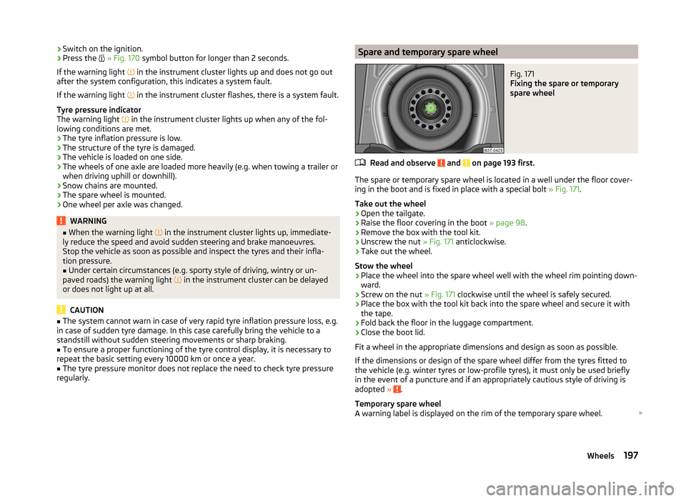
The spare or temporary spare wheel is located in a well under the floor cover-
ing in the boot and is fixed in place with a special bolt » Fig. 171.
Take out the wheel
›
Open the tailgate.
›
Raise the floor covering in the boot » page 98.
›
Remove the box with the tool kit.
›
Unscrew the nut » Fig. 171 anticlockwise.
›
Take out the wheel.
Stow the wheel
›
Place the wheel into the spare wheel well with the wheel rim pointing down-
ward.
›
Screw on the nut » Fig. 171 clockwise until the wheel is safely secured.
›
Place the box with the tool kit back into the spare wheel and secure it with
the tape.
›
Fold back the floor in the luggage compartment.
›
Close the boot lid.
Fit a wheel in the appropriate dimensions and design as soon as possible.
If the dimensions or design of the spare wheel differ from the tyres fitted to
the vehicle (e.g. winter tyres or low-profile tyres), it must only be used briefly
in the event of a puncture and if an appropriately cautious style of driving is
adopted »
.
Temporary spare wheel
A warning label is displayed on the rim of the temporary spare wheel.
197Wheels
Page 210 of 246
Negative cable - colour coding in the majority of cases is black.
Jump-starting in vehicles with the START-STOP system
Fig. 183
Engine earth: START-STOP sys-
tem
Read and observe and on page 207 first.
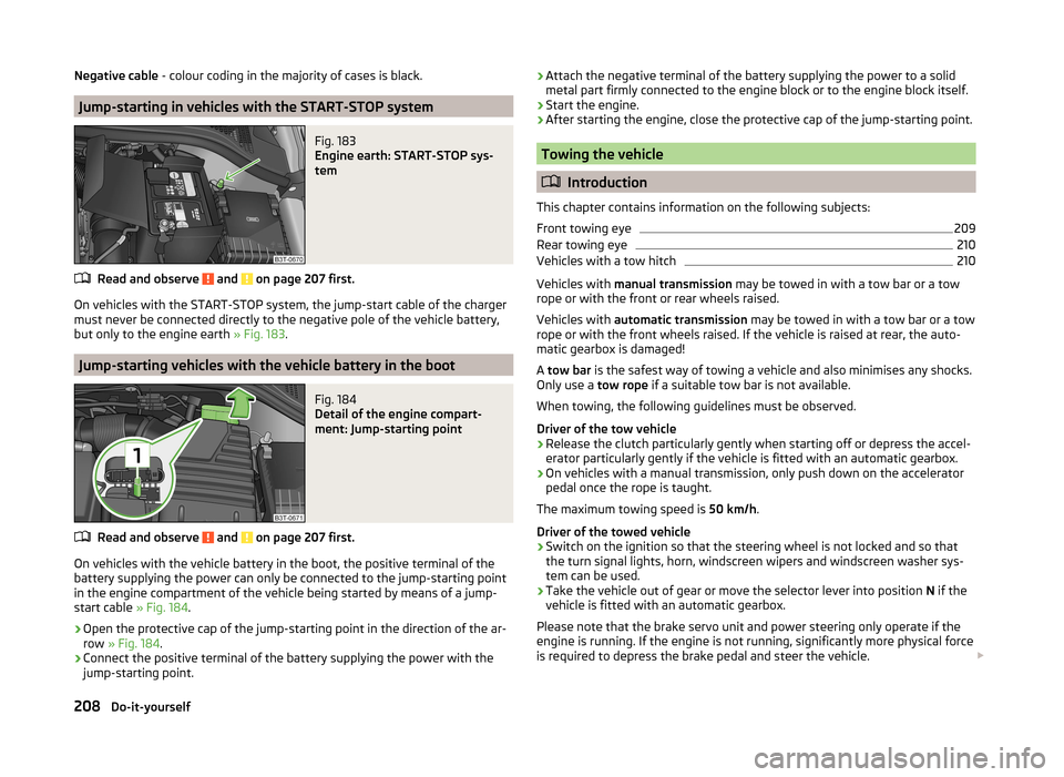
On vehicles with the START-STOP system, the jump-start cable of the charger
must never be connected directly to the negative pole of the vehicle battery,
but only to the engine earth » Fig. 183.
Jump-starting vehicles with the vehicle battery in the boot
Fig. 184
Detail of the engine compart-
ment: Jump-starting point
Read and observe and on page 207 first.
On vehicles with the vehicle battery in the boot, the positive terminal of the
battery supplying the power can only be connected to the jump-starting point
in the engine compartment of the vehicle being started by means of a jump-
start cable » Fig. 184.
›
Open the protective cap of the jump-starting point in the direction of the ar-
row » Fig. 184 .
›
Connect the positive terminal of the battery supplying the power with the
jump-starting point.
› Attach the negative terminal of the battery supplying the power to a solid
metal part firmly connected to the engine block or to the engine block itself.›
Start the engine.
›
After starting the engine, close the protective cap of the jump-starting point.
Towing the vehicle
Introduction
This chapter contains information on the following subjects:
Front towing eye
209
Rear towing eye
210
Vehicles with a tow hitch
210
Vehicles with manual transmission may be towed in with a tow bar or a tow
rope or with the front or rear wheels raised.
Vehicles with automatic transmission may be towed in with a tow bar or a tow
rope or with the front wheels raised. If the vehicle is raised at rear, the auto-
matic gearbox is damaged!
A tow bar is the safest way of towing a vehicle and also minimises any shocks.
Only use a tow rope if a suitable tow bar is not available.
When towing, the following guidelines must be observed.
Driver of the tow vehicle
›
Release the clutch particularly gently when starting off or depress the accel-
erator particularly gently if the vehicle is fitted with an automatic gearbox.
›
On vehicles with a manual transmission, only push down on the accelerator
pedal once the rope is taught.
The maximum towing speed is 50 km/h.
Driver of the towed vehicle
›
Switch on the ignition so that the steering wheel is not locked and so that
the turn signal lights, horn, windscreen wipers and windscreen washer sys-
tem can be used.
›
Take the vehicle out of gear or move the selector lever into position N if the
vehicle is fitted with an automatic gearbox.
Please note that the brake servo unit and power steering only operate if the
engine is running. If the engine is not running, significantly more physical force
is required to depress the brake pedal and steer the vehicle.
208Do-it-yourself
Page 234 of 246
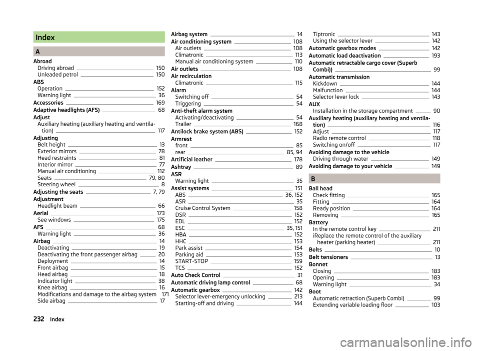
Index
A
Abroad Driving abroad
150
Unleaded petrol150
ABS Operation
152
Warning light36
Accessories169
Adaptive headlights (AFS)68
Adjust Auxiliary heating (auxiliary heating and ventila-tion)
117
Adjusting Belt height
13
Exterior mirrors78
Head restraints81
Interior mirror77
Manual air conditioning112
Seats79, 80
Steering wheel8
Adjusting the seats7, 79
Adjustment Headlight beam
66
Aerial173
See windows175
AFS68
Warning light36
Airbag14
Deactivating19
Deactivating the front passenger airbag20
Deployment14
Front airbag15
Head airbag18
Indicator light38
Knee airbag16
Modifications and damage to the airbag system 171 Side airbag
17
Airbag system14
Air conditioning system108
Air outlets108
Climatronic113
Manual air conditioning system110
Air outlets108
Air recirculation Climatronic
115
Alarm Switching off
54
Triggering54
Anti-theft alarm system Activating/deactivating
54
Trailer168
Antilock brake system (ABS)152
Armrest front
85
rear85, 94
Artificial leather178
Ashtray89
ASR Warning light
35
Assist systems151
ABS36, 152
ASR35
Cruise Control System158
DSR152
EDL152
ESC35, 151
HBA152
HHC153
Park assist154
Parking aid153
START-STOP159
TCS152
Auto Check Control31
Automatic driving lamp control68
Automatic gearbox142
Selector lever-emergency unlocking213
Starting-off and driving144
Tiptronic143
Using the selector lever142
Automatic gearbox modes142
Automatic load deactivation193
Automatic retractable cargo cover (Superb Combi))
99
Automatic transmission Kickdown
144
Malfunction144
Selector lever lock143
AUX Installation in the storage compartment
90
Auxiliary heating (auxiliary heating and ventila- tion)
116
Adjust117
Radio remote control118
Switching on/off117
Avoiding damage to the vehicle Driving through water
149
Avoiding damage to your vehicle149
B
Ball head Check fitting
165
Fitting164
Ready position164
Removing165
Battery In the remote control key
211
iReplace the remote control of the auxiliary heater (parking heater)
211
Belts10
Belt tensioners13
Bonnet Closing
183
Opening183
Warning light34
Boot Automatic retraction (Superb Combi)
99
Extending variable loading floor103
232Index