lights SKODA SUPERB 2014 2.G / (B6/3T) Manual PDF
[x] Cancel search | Manufacturer: SKODA, Model Year: 2014, Model line: SUPERB, Model: SKODA SUPERB 2014 2.G / (B6/3T)Pages: 246, PDF Size: 17.16 MB
Page 192 of 246
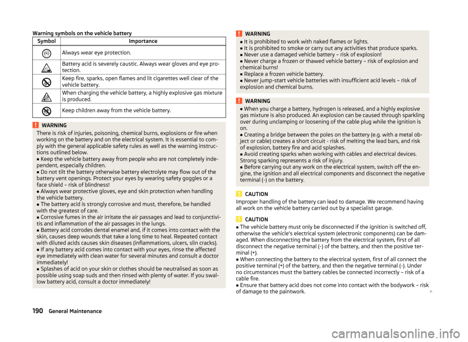
Warning symbols on the vehicle batterySymbolImportanceAlways wear eye protection.Battery acid is severely caustic. Always wear gloves and eye pro-
tection.Keep fire, sparks, open flames and lit cigarettes well clear of the
vehicle battery.When charging the vehicle battery, a highly explosive gas mixture
is produced.Keep children away from the vehicle battery.WARNINGThere is risk of injuries, poisoning, chemical burns, explosions or fire when
working on the battery and on the electrical system. It is essential to com-
ply with the general applicable safety rules as well as the warning instruc-
tions outlined below.■
Keep the vehicle battery away from people who are not completely inde-
pendent, especially children.
■
Do not tilt the battery otherwise battery electrolyte may flow out of the
battery vent openings. Protect your eyes by wearing safety goggles or a
face shield – risk of blindness!
■
Always wear protective gloves, eye and skin protection when handling
the vehicle battery.
■
The battery acid is strongly corrosive and must, therefore, be handled
with the greatest of care.
■
Corrosive fumes in the air irritate the air passages and lead to conjunctivi-
tis and inflammation of the air passages in the lungs.
■
Battery acid corrodes dental enamel and, if it comes into contact with the
skin, causes deep wounds that take a long time to heal. Repeated contact
with diluted acids causes skin diseases (inflammations, ulcers, slin cracks).
■
If any battery acid comes into contact with your eyes, rinse the affected
eye immediately with clean water for several minutes and consult a doctor
immediately!
■
Splashes of acid on your skin or clothes should be neutralised as soon as
possible using soap suds and then rinsed with plenty of water. If you swal-
low battery acid, consult a doctor immediately!
WARNING■ It is prohibited to work with naked flames or lights.■It is prohibited to smoke or carry out any activities that produce sparks.■
Never use a damaged vehicle battery – risk of explosion!
■
Never charge a frozen or thawed vehicle battery – risk of explosion and
chemical burns!
■
Replace a frozen vehicle battery.
■
Never jump-start vehicle batteries with insufficient acid levels – risk of
explosion and chemical burns.
WARNING■ When you charge a battery, hydrogen is released, and a highly explosive
gas mixture is also produced. An explosion can be caused through sparkling
over during unclamping or loosening of the cable plug while the ignition is
on.■
Creating a bridge between the poles on the battery (e.g. with a metal ob-
ject or cable) creates a short circuit - risk of melting the lead bars, and risk
of explosion, battery fire and acid splashes.
■
Avoid creating sparks when working with cables and electrical devices.
Strong sparking represents a risk of injury.
■
Before carrying out any work on the electrical system, switch off the en-
gine, the ignition and all electrical components and disconnect the negative
terminal (-) on the battery.
CAUTION
Improper handling of the battery can lead to damage. We recommend having
all work on the vehicle battery carried out by a specialist garage.
CAUTION
■ The vehicle battery must only be disconnected if the ignition is switched off,
otherwise the vehicle's electrical system (electronic components) can be dam-
aged. When disconnecting the battery from the electrical system, first of all
disconnect the negative terminal (-) of the battery, and then the positive ter-
minal (+).■
When connecting the battery to the electrical system, first of all connect the
positive terminal (+) of the battery, and then the negative terminal (-). Under
no circumstances must the battery cables be connected incorrectly – risk of a
cable fire.
■
Ensure that battery acid does not come into contact with the bodywork – risk
of damage to the paintwork.
190General Maintenance
Page 195 of 246
OperationOperating measureSetting the clock» page 30Data in the multifunction display are de-
leted.» page 41
Note
We recommend having the vehicle checked by a specialist garage in order to
ensure full functionality of all electrical systems.
Automatic load deactivation
Read and observe
and on page 190 first.
The vehicle voltage control unit automatically prevents the battery from dis-
charging when the battery is put under high levels of strain. This manifests it-
self by the following.
› The idling speed is raised to allow the generator to deliver more electricity to
the electrical system.
› Where necessary, large convenience consumers such as seat heaters and
rear window heaters have their power limited or are shut off completely in
the event of an emergency.
CAUTION
■ Despite such intervention by the vehicle electric system management, the
vehicle battery may be drained. For example, when the ignition is switched on
a long time with the engine turned off or the side or parking lights are turned
on during longer parking.■
Consumers that are supplied via a 12-V power socket can cause the vehicle
battery to discharge when the ignition is switched off.
Note
Driving comfort is not impaired by consumers being deactivated. The driver is
often not aware of it having taken place.Wheels
Tyres and wheel rims
Introduction
This chapter contains information on the following subjects:
Service life of tyres
194
New tyres
195
Unidirectional tyres
196
Tyre pressure monitor
196
Spare and temporary spare wheel
197
Full wheel trim
198
Wheel bolts
198
Wheel bolts
198WARNINGThe national legal regulations must be observed for the use of tyres.WARNINGInstructions for the use of tyres■For the first 500 km, new tyres do not yet provide optimum grip, and ap-
propriate care should therefore be taken when driving – risk of accident!■
Only use radial tyres of the same type, size (rolling circumference) and
tread pattern on all four wheels.
■
For reasons of driving safety, do not replace tyres individually.
■
Never exceed the maximum permissible load bearing capacity for fitted
tyres – risk of accident!
■
Never exceed the maximum permissible speed for fitted tyres – risk of ac-
cident!
■
Incorrect wheel alignment at the front or rear impairs handling – risk of
accident!
■
Unusual vibrations or pulling of the vehicle to one side could be a sign of
tyre damage. If there is any doubt that a wheel is damaged, immediately re-
duce your speed and stop! If no external damage is evident, drive slowly
and carefully to the nearest specialist garage to have the vehicle checked.
■
Only use tyres or wheel rims that have been approved by ŠKODA for your
model of vehicle. Failure to observe this instruction may impair the road
safety of your vehicle – risk of accident!
193Wheels
Page 198 of 246
Where possible, replace tyres by axle. Always fit the tyres with the deeper
tread depth to the front wheels.
Explanation of tyre markings
205/55 R 16 94 V
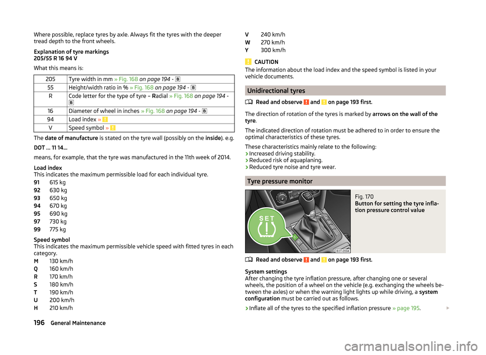
What this means is:205Tyre width in mm » Fig. 168 on page 194 - 55Height/width ratio in % » Fig. 168 on page 194 - RCode letter for the type of tyre – Radial » Fig. 168 on page 194 -
16Diameter of wheel in inches » Fig. 168 on page 194 - 94Load index » VSpeed symbol »
The date of manufacture is stated on the tyre wall (possibly on the inside). e.g.
DOT ... 11 14...
means, for example, that the tyre was manufactured in the 11th week of 2014.
Load index
This indicates the maximum permissible load for each individual tyre.
615 kg
630 kg
650 kg
670 kg
690 kg
730 kg
775 kg
Speed symbol
This indicates the maximum permissible vehicle speed with fitted tyres in each
category.
130 km/h
160 km/h
170 km/h
180 km/h
190 km/h
200 km/h
210 km/h
91929394959799MQRSTUH240 km/h
270 km/h
300 km/h
CAUTION
The information about the load index and the speed symbol is listed in your
vehicle documents.
Unidirectional tyres
Read and observe
and on page 193 first.
The direction of rotation of the tyres is marked by arrows on the wall of the
tyre .
The indicated direction of rotation must be adhered to in order to ensure the
optimal characteristics of these tyres.
These characteristics mainly relate to the following: › Increased driving stability.
› Reduced risk of aquaplaning.
› Reduced tyre noise and tyre wear.
Tyre pressure monitor
Fig. 170
Button for setting the tyre infla-
tion pressure control value
Read and observe and on page 193 first.
System settings
After changing the tyre inflation pressure, after changing one or several
wheels, the position of a wheel on the vehicle (e.g. exchanging the wheels be-
tween the axles) or when the warning light lights up while driving, a system
configuration must be carried out as follows.
›
Inflate all of the tyres to the specified inflation pressure » page 195.
V
WY196General Maintenance
Page 199 of 246
›Switch on the ignition.›Press the
» Fig. 170 symbol button for longer than 2 seconds.
If the warning light
in the instrument cluster lights up and does not go out
after the system configuration, this indicates a system fault.
If the warning light
in the instrument cluster flashes, there is a system fault.
Tyre pressure indicator
The warning light
in the instrument cluster lights up when any of the fol-
lowing conditions are met.
› The tyre inflation pressure is low.
› The structure of the tyre is damaged.
› The vehicle is loaded on one side.
› The wheels of one axle are loaded more heavily (e.g. when towing a trailer or
when driving uphill or downhill).
› Snow chains are mounted.
› The spare wheel is mounted.
› One wheel per axle was changed.WARNING■
When the warning light in the instrument cluster lights up, immediate-
ly reduce the speed and avoid sudden steering and brake manoeuvres.
Stop the vehicle as soon as possible and inspect the tyres and their infla-
tion pressure.■
Under certain circumstances (e.g. sporty style of driving, wintry or un-
paved roads) the warning light
in the instrument cluster can be delayed
or does not light up at all.
CAUTION
■ The system cannot warn in case of very rapid tyre inflation pressure loss, e.g.
in case of sudden tyre damage. In this case carefully bring the vehicle to a
standstill without sudden steering movements or sharp braking.■
To ensure a proper functioning of the tyre control display, it is necessary to
repeat the basic setting every 10000 km or once a year.
■
The tyre pressure monitor does not replace the need to check tyre pressure
regularly.
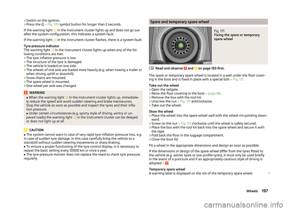
Spare and temporary spare wheelFig. 171
Fixing the spare or temporary
spare wheel
Read and observe and on page 193 first.
The spare or temporary spare wheel is located in a well under the floor cover-
ing in the boot and is fixed in place with a special bolt » Fig. 171.
Take out the wheel
›
Open the tailgate.
›
Raise the floor covering in the boot » page 98.
›
Remove the box with the tool kit.
›
Unscrew the nut » Fig. 171 anticlockwise.
›
Take out the wheel.
Stow the wheel
›
Place the wheel into the spare wheel well with the wheel rim pointing down-
ward.
›
Screw on the nut » Fig. 171 clockwise until the wheel is safely secured.
›
Place the box with the tool kit back into the spare wheel and secure it with
the tape.
›
Fold back the floor in the luggage compartment.
›
Close the boot lid.
Fit a wheel in the appropriate dimensions and design as soon as possible.
If the dimensions or design of the spare wheel differ from the tyres fitted to
the vehicle (e.g. winter tyres or low-profile tyres), it must only be used briefly
in the event of a puncture and if an appropriately cautious style of driving is
adopted »
.
Temporary spare wheel
A warning label is displayed on the rim of the temporary spare wheel.
197Wheels
Page 210 of 246
Negative cable - colour coding in the majority of cases is black.
Jump-starting in vehicles with the START-STOP system
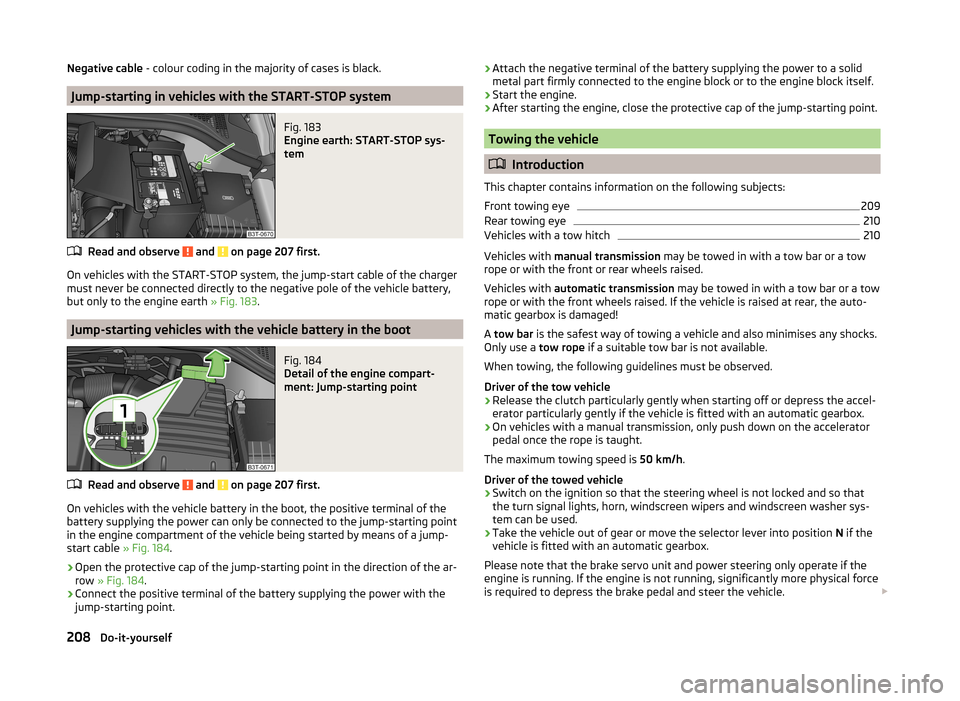
Fig. 183
Engine earth: START-STOP sys-
tem
Read and observe and on page 207 first.
On vehicles with the START-STOP system, the jump-start cable of the charger
must never be connected directly to the negative pole of the vehicle battery,
but only to the engine earth » Fig. 183.
Jump-starting vehicles with the vehicle battery in the boot
Fig. 184
Detail of the engine compart-
ment: Jump-starting point
Read and observe and on page 207 first.
On vehicles with the vehicle battery in the boot, the positive terminal of the
battery supplying the power can only be connected to the jump-starting point
in the engine compartment of the vehicle being started by means of a jump-
start cable » Fig. 184.
›
Open the protective cap of the jump-starting point in the direction of the ar-
row » Fig. 184 .
›
Connect the positive terminal of the battery supplying the power with the
jump-starting point.
› Attach the negative terminal of the battery supplying the power to a solid
metal part firmly connected to the engine block or to the engine block itself.›
Start the engine.
›
After starting the engine, close the protective cap of the jump-starting point.
Towing the vehicle
Introduction
This chapter contains information on the following subjects:
Front towing eye
209
Rear towing eye
210
Vehicles with a tow hitch
210
Vehicles with manual transmission may be towed in with a tow bar or a tow
rope or with the front or rear wheels raised.
Vehicles with automatic transmission may be towed in with a tow bar or a tow
rope or with the front wheels raised. If the vehicle is raised at rear, the auto-
matic gearbox is damaged!
A tow bar is the safest way of towing a vehicle and also minimises any shocks.
Only use a tow rope if a suitable tow bar is not available.
When towing, the following guidelines must be observed.
Driver of the tow vehicle
›
Release the clutch particularly gently when starting off or depress the accel-
erator particularly gently if the vehicle is fitted with an automatic gearbox.
›
On vehicles with a manual transmission, only push down on the accelerator
pedal once the rope is taught.
The maximum towing speed is 50 km/h.
Driver of the towed vehicle
›
Switch on the ignition so that the steering wheel is not locked and so that
the turn signal lights, horn, windscreen wipers and windscreen washer sys-
tem can be used.
›
Take the vehicle out of gear or move the selector lever into position N if the
vehicle is fitted with an automatic gearbox.
Please note that the brake servo unit and power steering only operate if the
engine is running. If the engine is not running, significantly more physical force
is required to depress the brake pedal and steer the vehicle.
208Do-it-yourself
Page 218 of 246
CAUTION■“Never repair” fuses or replace them with a fuse of a higher amperage – risk
of fire! This may also cause damage at another part of the electrical system.■
If a newly inserted fuse blows again after a short time, have the electrical
system checked as quickly as possible by a specialist garage.
■
A blown fuses is recognisable by the molten metal strip. Replace the faulty
fuse with a new one of the same amperage.
Note
■
We recommend always carrying replacement fuses in the vehicle. A box of
replacement fuses can be purchased from ŠKODA Original Accessories.■
There can be several power consuming devices for one fuse.
■
Multiple fuses may exist for a single power consuming device.
Fuses in the dash panel
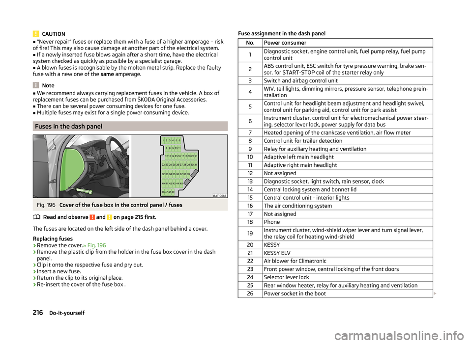
Fig. 196
Cover of the fuse box in the control panel / fuses
Read and observe
and on page 215 first.
The fuses are located on the left side of the dash panel behind a cover.
Replacing fuses
›
Remove the cover. » Fig. 196
›
Remove the plastic clip from the holder in the fuse box cover in the dash
panel.
›
Clip it onto the respective fuse and pry out.
›
Insert a new fuse.
›
Return the clip to its original place.
›
Re-insert the cover of the fuse box .
Fuse assignment in the dash panelNo.Power consumer1Diagnostic socket, engine control unit, fuel pump relay, fuel pump
control unit2ABS control unit, ESC switch for tyre pressure warning, brake sen-
sor, for START-STOP coil of the starter relay only3Switch and airbag control unit4WIV, tail lights, dimming mirrors, pressure sensor, telephone prein-
stallation5Control unit for headlight beam adjustment and headlight swivel,
control unit for parking aid, control unit for park assist6Instrument cluster, control unit for electromechanical power steer-
ing, selector lever lock, power supply for data bus7Heated opening of the crankcase ventilation, air flow meter8Control unit for trailer detection9Relay for auxiliary heating and ventilation10Adaptive left main headlight11Adaptive right main headlight12Not assigned13Diagnostic socket, light switch, rain sensor, clock14Central locking system and bonnet lid15Central control unit - interior lights16The air conditioning system17Not assigned18Phone19Instrument cluster, wind-shield wiper lever and turn signal lever,
the relay coil for heating wind-shield20KESSY21KESSY ELV22Air blower for Climatronic23Front power window, central locking of the front doors24Selector lever lock25Rear window heater, relay for auxiliary heating and ventilation26Power socket in the boot 216Do-it-yourself
Page 221 of 246
No.Consumer11Auxiliary heating and ventilation control unit12Data bus control unit13Engine control unit14Ignition15Lambda probe (petrol engine), glow plug system relay and fuel
pump (diesel engine)16Front right main headlight, right tail light17Horn18Audio amplifier (sound system)19Windscreen wipers20Valve for metering fuel, coolant pump, high pressure pump21Lambda probe22Clutch pedal switch23Coil of the coolant pump relay valves, high-pressure pump24Radiator fan25Pump for ABS26Front left main headlight, left tail light27Control unit for glow plug system28Windscreen heater29Power to the internal fuse carrier30Power supply for terminal 15 (ignition on)a)
In order not to drain the battery unnecessarily when starting the engine, the electrical components of
this terminal are automatically switched off.
Bulbs
Introduction
This chapter contains information on the following subjects:
Headlights
220
Replacing the low beam bulb
220
Replacing bulb for main beam and daytime running lights
220
Replacing bulb for main beam
221
Replacing the bulb for the fog light
221Replacing the bulb for the licence plate light222Rear light (Superb Combi)222
Replacing bulbs in rear light (Superb Combi)
223
Some manual skills are required to change a bulb. For this reason, we recom-
mend having bulbs replaced by a specialist garage or seeking other expert help
in the event of any uncertainties.
› Switch off the ignition and all of the lights before replacing a bulb.
› Faulty bulbs must only be replaced with the same type of bulbs. The designa-
tion is located on the light socket or the glass bulb.
› A stowage compartment for replacement bulbs is located in a plastic box in
the spare wheel or underneath the floor covering in the boot.
WARNING■ Always read and observe the warnings before completing any work in the
engine compartment » page 182.■
Accidents can be caused if the road in front of the vehicle is not suffi-
ciently illuminated and the vehicle cannot or can only be seen with difficul-
ty by other road users.
■
Bulbs H7 H8 and H15 are pressurised and may burst when changing the
bulb - risk of injury! We therefore recommended wearing gloves and safety
glasses when changing a bulb.
■
Gas discharge bulbs (xenon bulbs) operate with a high voltage, professio-
nal knowledge is required – risk of death!
■
Switch off the respective vehicle light when changing the bulb.
CAUTION
Do not take hold of the glass bulb with naked fingers (even the smallest
amount of dirt reduces the working life of the light bulb). Use a clean cloth,
napkin, or similar.
Note
■ This Owner's Manual only describes the replacement of bulbs where it is pos-
sible to replace the bulbs on your own without any complications arising. Other
bulbs must be replaced by a specialist garage.■
We recommend that a box of replacement bulbs always be carried in the ve-
hicle. Replacement bulbs can be purchased from ŠKODAOriginal Accessories.
■
We recommend having the headlight settings checked by a specialist garage
after replacing a bulb in the main, low or fog beam.
■
In case of failure of a xenon gas discharge lamp or an LED diode, visit a spe-
cialist garage.
219Fuses and light bulbs
Page 222 of 246
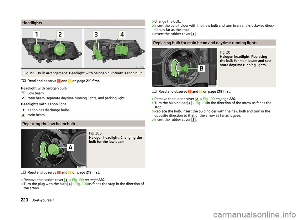
HeadlightsFig. 199
Bulb arrangement: Headlight with halogen bulb/with Xenon bulb
Read and observe
and on page 219 first.
Headlight with halogen bulb Low beam
Main beam, separate daytime running lights, and parking light
Headlights with Xenon light Xenon gas discharge bulbs
Main beam
Replacing the low beam bulb
Fig. 200
Halogen headlight: Changing the
bulb for the low beam
Read and observe and on page 219 first.
›
Remove the rubber cover
1
» Fig. 199 on page 220 .
›
Turn the plug with the bulb
A
» Fig. 200 as far as the stop in the direction of
the arrow.
1234› Change the bulb.›Insert the bulb holder with the new bulb and turn in an anti-clockwise direc-
tion as far as the stop.›
Insert the rubber cover
1
.
Replacing bulb for main beam and daytime running lights
Fig. 201
Halogen headlight: Replacing
the bulb for main beam and sep-
arate daytime running lights
Read and observe and on page 219 first.
›
Remove the rubber cover
2
» Fig. 199 on page 220 .
›
Turn the bulb holder
A
» Fig. 201 in the direction of the arrow as far as the
stop.
›
Replace the bulb, insert the bulb holder with the new bulb and turn in the
opposite direction to that of the arrow as far as it goes.
›
Insert the rubber cover
2
.
220Do-it-yourself
Page 223 of 246
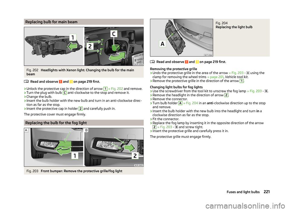
Replacing bulb for main beamFig. 202
Headlights with Xenon light: Changing the bulb for the main
beam
Read and observe
and on page 219 first.
›
Unlock the protective cap in the direction of arrow
1
» Fig. 202 and remove.
›
Turn the plug with bulb
C
anti-clockwise to the stop and remove it.
›
Change the bulb.
›
Insert the bulb holder with the new bulb and turn in an anti-clockwise direc-
tion as far as the stop.
›
Insert the protective cap in holder
2
and carefully push in.
The protective cover must engage firmly.
Replacing the bulb for the fog light
Fig. 203
Front bumper: Remove the protective grille/fog light
Fig. 204
Replacing the light bulb
Read and observe and on page 219 first.
Removing the protective grille
›
Undo the protective grille in the area of the arrow » Fig. 203 -
using the
clamp for removing the wheel trims » page 201, Vehicle tool kit .
›
Remove the protective grille in the direction of the arrow
1
.
Changing light bulbs for fog lights
›
Use the screwdriver from the tool kit to unscrew the fog lamp » Fig. 203 -
.
›
Remove the headlight in the direction of arrow
2
.
›
Remove the connector.
›
Turn bulb holder
A
» Fig. 204 in an anti-clockwise direction up to the stop
and remove.
›
Insert the bulb holder with the new bulb into the headlight and turn in a
clockwise direction as far as the stop.
›
Fit the connector.
›
Replace the fog lamp by inserting it in the opposite direction of the arrow
2
» Fig. 203 -
and screw tight.
›
Insert the protective grille and carefully press it in.
The protective grille must engage firmly.
221Fuses and light bulbs
Page 234 of 246
Index
A
Abroad Driving abroad
150
Unleaded petrol150
ABS Operation
152
Warning light36
Accessories169
Adaptive headlights (AFS)68
Adjust Auxiliary heating (auxiliary heating and ventila-tion)
117
Adjusting Belt height
13
Exterior mirrors78
Head restraints81
Interior mirror77
Manual air conditioning112
Seats79, 80
Steering wheel8
Adjusting the seats7, 79
Adjustment Headlight beam
66
Aerial173
See windows175
AFS68
Warning light36
Airbag14
Deactivating19
Deactivating the front passenger airbag20
Deployment14
Front airbag15
Head airbag18
Indicator light38
Knee airbag16
Modifications and damage to the airbag system 171 Side airbag
17
Airbag system14
Air conditioning system108
Air outlets108
Climatronic113
Manual air conditioning system110
Air outlets108
Air recirculation Climatronic
115
Alarm Switching off
54
Triggering54
Anti-theft alarm system Activating/deactivating
54
Trailer168
Antilock brake system (ABS)152
Armrest front
85
rear85, 94
Artificial leather178
Ashtray89
ASR Warning light
35
Assist systems151
ABS36, 152
ASR35
Cruise Control System158
DSR152
EDL152
ESC35, 151
HBA152
HHC153
Park assist154
Parking aid153
START-STOP159
TCS152
Auto Check Control31
Automatic driving lamp control68
Automatic gearbox142
Selector lever-emergency unlocking213
Starting-off and driving144
Tiptronic143
Using the selector lever142
Automatic gearbox modes142
Automatic load deactivation193
Automatic retractable cargo cover (Superb Combi))
99
Automatic transmission Kickdown
144
Malfunction144
Selector lever lock143
AUX Installation in the storage compartment
90
Auxiliary heating (auxiliary heating and ventila- tion)
116
Adjust117
Radio remote control118
Switching on/off117
Avoiding damage to the vehicle Driving through water
149
Avoiding damage to your vehicle149
B
Ball head Check fitting
165
Fitting164
Ready position164
Removing165
Battery In the remote control key
211
iReplace the remote control of the auxiliary heater (parking heater)
211
Belts10
Belt tensioners13
Bonnet Closing
183
Opening183
Warning light34
Boot Automatic retraction (Superb Combi)
99
Extending variable loading floor103
232Index