lights SKODA SUPERB 2014 2.G / (B6/3T) Service Manual
[x] Cancel search | Manufacturer: SKODA, Model Year: 2014, Model line: SUPERB, Model: SKODA SUPERB 2014 2.G / (B6/3T)Pages: 246, PDF Size: 17.16 MB
Page 94 of 246
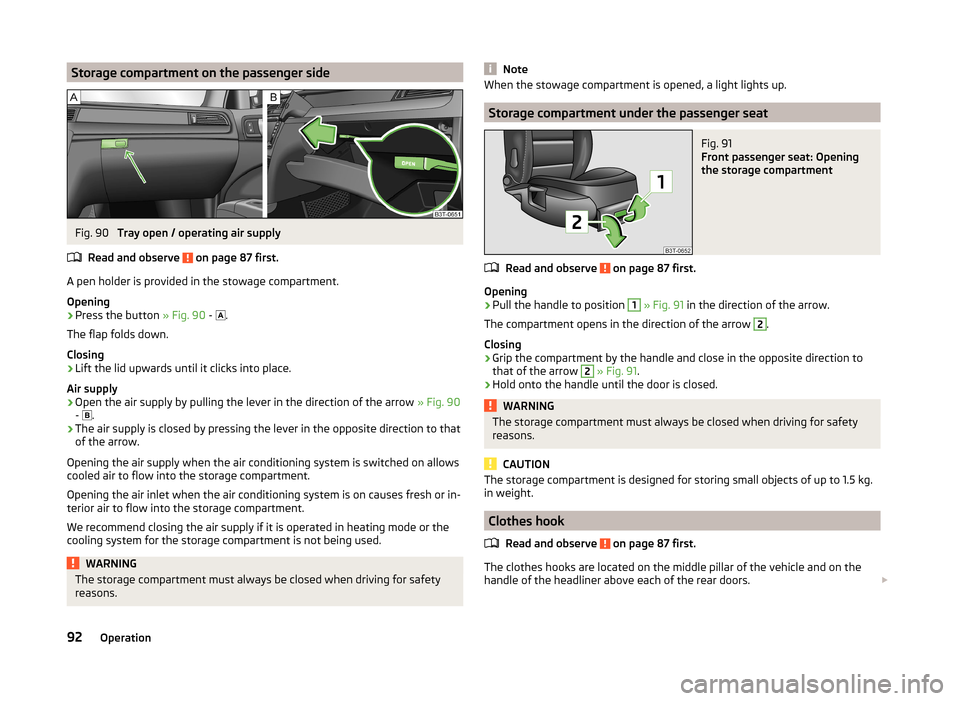
Storage compartment on the passenger sideFig. 90
Tray open / operating air supply
Read and observe
on page 87 first.
A pen holder is provided in the stowage compartment.
Opening
›
Press the button » Fig. 90 -
.
The flap folds down.
Closing
›
Lift the lid upwards until it clicks into place.
Air supply
›
Open the air supply by pulling the lever in the direction of the arrow » Fig. 90
- .
›
The air supply is closed by pressing the lever in the opposite direction to that
of the arrow.
Opening the air supply when the air conditioning system is switched on allows cooled air to flow into the storage compartment.
Opening the air inlet when the air conditioning system is on causes fresh or in-
terior air to flow into the storage compartment.
We recommend closing the air supply if it is operated in heating mode or the
cooling system for the storage compartment is not being used.
WARNINGThe storage compartment must always be closed when driving for safety
reasons.NoteWhen the stowage compartment is opened, a light lights up.
Storage compartment under the passenger seat
Fig. 91
Front passenger seat: Opening
the storage compartment
Read and observe on page 87 first.
Opening
›
Pull the handle to position
1
» Fig. 91 in the direction of the arrow.
The compartment opens in the direction of the arrow
2
.
Closing
›
Grip the compartment by the handle and close in the opposite direction to
that of the arrow
2
» Fig. 91 .
›
Hold onto the handle until the door is closed.
WARNINGThe storage compartment must always be closed when driving for safety
reasons.
CAUTION
The storage compartment is designed for storing small objects of up to 1.5 kg.
in weight.
Clothes hook
Read and observe
on page 87 first.
The clothes hooks are located on the middle pillar of the vehicle and on the
handle of the headliner above each of the rear doors.
92Operation
Page 103 of 246
Removable light (Superb Combi)
Introduction
This chapter contains information on the following subjects:
Use light
101
Changing rechargeable light batteries
101
A removable lamp is fitted on the left side of the boot. This lamp has two func-
tions.
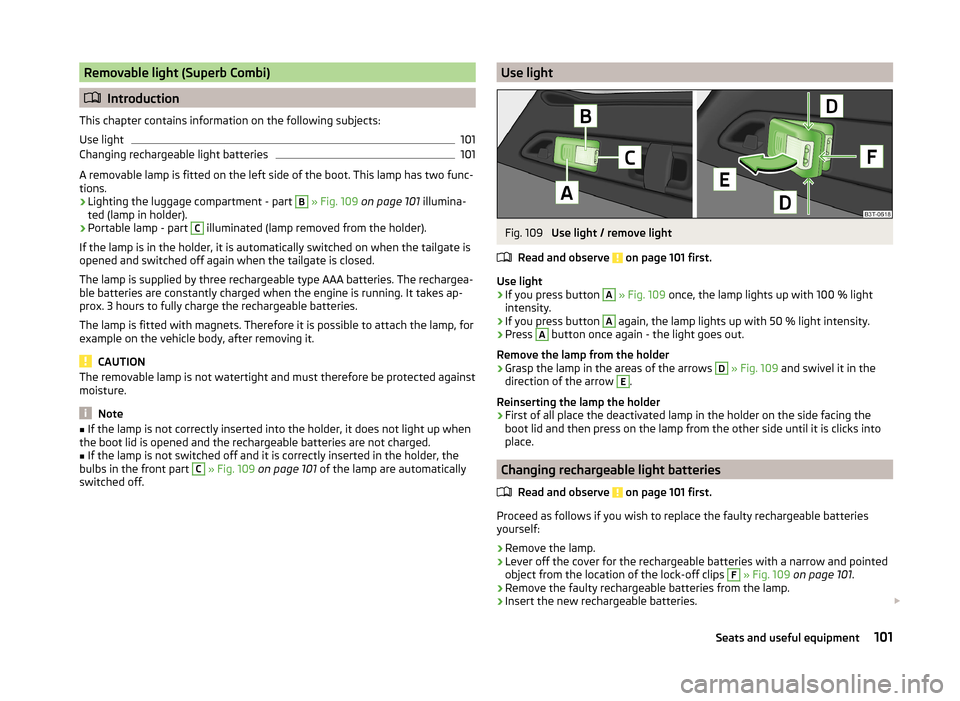
› Lighting the luggage compartment - part
B
» Fig. 109 on page 101 illumina-
ted (lamp in holder).
› Portable lamp - part
C
illuminated (lamp removed from the holder).
If the lamp is in the holder, it is automatically switched on when the tailgate is
opened and switched off again when the tailgate is closed.
The lamp is supplied by three rechargeable type AAA batteries. The rechargea-
ble batteries are constantly charged when the engine is running. It takes ap-
prox. 3 hours to fully charge the rechargeable batteries.
The lamp is fitted with magnets. Therefore it is possible to attach the lamp, for example on the vehicle body, after removing it.
CAUTION
The removable lamp is not watertight and must therefore be protected against
moisture.
Note
■ If the lamp is not correctly inserted into the holder, it does not light up when
the boot lid is opened and the rechargeable batteries are not charged.■
If the lamp is not switched off and it is correctly inserted in the holder, the
bulbs in the front part
C
» Fig. 109 on page 101 of the lamp are automatically
switched off.
Use lightFig. 109
Use light / remove light
Read and observe
on page 101 first.
Use light
›
If you press button
A
» Fig. 109 once, the lamp lights up with 100 % light
intensity.
›
If you press button
A
again, the lamp lights up with 50 % light intensity.
›
Press
A
button once again - the light goes out.
Remove the lamp from the holder
›
Grasp the lamp in the areas of the arrows
D
» Fig. 109 and swivel it in the
direction of the arrow
E
.
Reinserting the lamp the holder
›
First of all place the deactivated lamp in the holder on the side facing the
boot lid and then press on the lamp from the other side until it is clicks into
place.
Changing rechargeable light batteries
Read and observe
on page 101 first.
Proceed as follows if you wish to replace the faulty rechargeable batteries
yourself:
›
Remove the lamp.
›
Lever off the cover for the rechargeable batteries with a narrow and pointed
object from the location of the lock-off clips
F
» Fig. 109 on page 101 .
›
Remove the faulty rechargeable batteries from the lamp.
›
Insert the new rechargeable batteries.
101Seats and useful equipment
Page 113 of 246
NoteThe warning light in the symbol button lights after activation, even if not all
of the conditions for the function of the cooling system are met » page 110. By
lighting up of the indicator light in the button, the operational readiness of the
cooling system is signalled.111Air conditioning system
Page 114 of 246
adjustingRead and observe
on page 110 first.
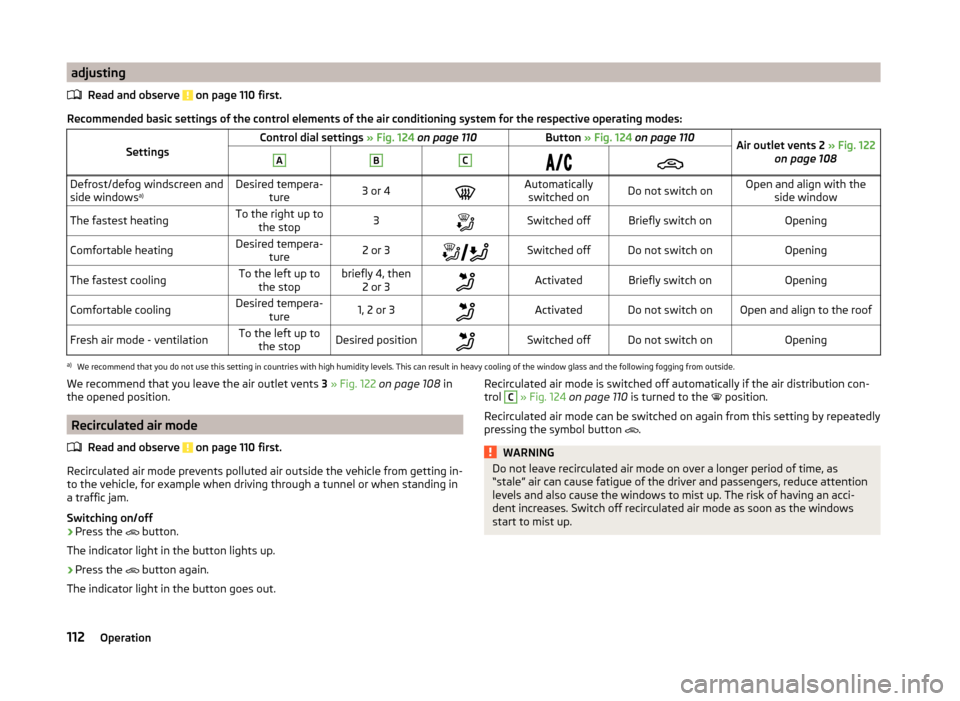
Recommended basic settings of the control elements of the air conditioning system for the respective operating modes:
SettingsControl dial settings » Fig. 124 on page 110Button » Fig. 124 on page 110Air outlet vents 2 » Fig. 122
on page 108ABCDefrost/defog windscreen and
side windows a)Desired tempera-
ture3 or 4Automaticallyswitched onDo not switch onOpen and align with the side windowThe fastest heatingTo the right up tothe stop3Switched offBriefly switch onOpeningComfortable heatingDesired tempera- ture2 or 3Switched offDo not switch onOpeningThe fastest coolingTo the left up to
the stopbriefly 4, then 2 or 3ActivatedBriefly switch onOpeningComfortable coolingDesired tempera- ture1, 2 or 3ActivatedDo not switch onOpen and align to the roofFresh air mode - ventilationTo the left up tothe stopDesired positionSwitched offDo not switch onOpeninga)
We recommend that you do not use this setting in countries with high humidity levels. This can result in heavy cooling of the window glass and the following fogging from outside.
We recommend that you leave the air outlet vents 3 » Fig. 122 on page 108 in
the opened position.
Recirculated air mode
Read and observe
on page 110 first.
Recirculated air mode prevents polluted air outside the vehicle from getting in-to the vehicle, for example when driving through a tunnel or when standing in
a traffic jam.
Switching on/off
›
Press the button.
The indicator light in the button lights up.
›
Press the button again.
The indicator light in the button goes out.
Recirculated air mode is switched off automatically if the air distribution con-
trol C » Fig. 124 on page 110 is turned to the position.
Recirculated air mode can be switched on again from this setting by repeatedly pressing the symbol button
.WARNINGDo not leave recirculated air mode on over a longer period of time, as
“stale” air can cause fatigue of the driver and passengers, reduce attention
levels and also cause the windows to mist up. The risk of having an acci-
dent increases. Switch off recirculated air mode as soon as the windows
start to mist up.112Operation
Page 116 of 246
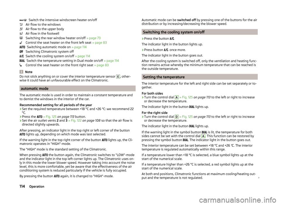
Switch the intensive windscreen heater on/off
Air flow to the windows
Air flow to the upper body
Air flow in the footwell
Switching the rear window heater on/off » page 73
Control the seat heater on the front left seat » page 83
Switching automatic mode on » page 114
Switching Climatronic system off
Switch the cooling system on/off » page 114
Switch the temperature setting in Dual mode on/off » page 114
Control the seat heater on the front right seat » page 83
Note
Do not stick anything on or cover the interior temperature sensor E, other-
wise it could have an unfavourable effect on the Climatronic.
automatic mode
The automatic mode is used in order to maintain a constant temperature and
to demist the windows in the interior of the car.
Recommended setting for all periods of the year
›
Set the required temperature between +18 °C and +26 °C: we recommend 22
°C.
›
Press the
» Fig. 125 on page 113 button.
›
Set the air outlet vents 2 and 3 » Fig. 122 on page 108 so that the air flow is
directed slightly upwards.
After pressing, an indicator light in the top right or left corner of the button
lights up, depending on which mode was last selected.
If the warning light in the top right corner of the button lights up, the Cli-
matronic operates in “HIGH”-mode.
The “HIGH” mode is the standard setting of the Climatronic.
When pressing the button again, the Climatronic switches to “LOW”-mode
and the indicator light in the top left corner lights up. The Climatronic uses on-
ly in this mode the lower blower speed. However taking into account the noise
level, this is more comfortable, yet be aware that the effectiveness of the air
conditioning system is reduced particularly if the vehicle is fully occupied.
By pressing the button again, it is changed to “HIGH”-mode.
Automatic mode can be
switched off by pressing one of the buttons for the air
distribution or by increasing/decreasing the blower speed.
Switching the cooling system on/off
›
Press the button
.
The indicator light in the button lights up.
›
Press button
. once more.
The indicator light in the button goes out.
After the cooling system is switched off, only the ventilation and heating func-
tion remains active whereby the minimum temperature that can be reached is
the outside temperature.
Setting the temperature
The interior temperature for the left and right side can be set separately or to-
gether.
For both sides
›
Turn the control dial
A
» Fig. 125 on page 113 to the left or right to increase
or decrease the temperature.
The indicator light in the button lights up.
For the right side
›
Turn the control dial
D
» Fig. 125 on page 113 to the left or right to increase
or decrease the temperature.
The indicator light in the button lights up.
If the warning light in the symbol button is lit, the temperature for both
sides cannot be set with the control dial
A
. This function can be restored by
pressing the symbol button . The indicator light in the button goes out.
The interior temperature can be set between +18 °C and +26 ℃. The interior
temperature is regulated automatically within this range.
If a temperature lower than +18 °C is selected, a blue symbol lights up at the start of the numerical scale.
If a temperature higher than +26 °C is selected, a red symbol lights up at the
start of the numerical scale.
At both end positions, Climatronic functions at maximum cooling/heating out-
put and the temperature is not regulated.
114Operation
Page 117 of 246
CAUTIONLengthy and uneven distribution of the air flow out of the vents (especially
around the feet) and large differences in temperature, for example, when get-
ting out of the vehicle, can cause susceptible individuals to catch a cold.
Recirculation mode - Version 1
Recirculated air mode prevents polluted air outside the vehicle from getting in-
to the vehicle, for example when driving through a tunnel or when standing in
a traffic jam.
If a considerable increase in concentration of pollutants is recognised by the air quality sensor, recirculated air mode will temporarily be switched off.
If the concentration of pollutants decreases to the normal level, the air distri-
bution control is automatically switched off so that fresh air can be guided into
the vehicle interior.
In recirculated air mode air is sucked out of the interior of the vehicle and then
fed back into the interior.
When the automatic air distribution control is switched on, an air quality sen-
sor measures the concentration of pollutants in the drawn in air.
Switching recirculated air mode on
›
Repeatedly press the button until the indicator light on the
left side of
the button is illuminated.
Switch on automatic air distribution control
›
Repeatedly press the button until the warning light on the
right-hand
side of the button lights up.
Switch off automatic air distribution control temporarily
If the air quality sensor does not switch on automatic recirculated air mode
when there is an unpleasant smell, you can switch it on manually.
›
Press the symbol button .
The indicator light lights up in the button on the left side.
Switching recirculated air mode off
›
Press the button or press the symbol button
again until the warning
lights in the button go out.
WARNINGDo not leave recirculated air mode on over a longer period of time, as
“stale” air can cause fatigue of the driver and passengers, reduce attention
levels and also cause the windows to mist up. The risk of having an acci-
dent increases. Switch off recirculated air mode as soon as the windows
start to mist up.
Note
■ If the windscreen mists up, press the symbol button . Press the button
once the windscreen has demisted.■
The automatic air distribution control operates only if the outside tempera-
ture is higher than approx. 2 °C.
Recirculation mode - Version 2
Recirculated air mode prevents polluted air outside the vehicle from getting in-
to the vehicle, for example when driving through a tunnel or when standing in
a traffic jam.
In recirculated air mode air is sucked out of the interior of the vehicle and then
fed back into the interior.
The air recirculation mode is automatically activated after the ignition is
switched if it was on before the ignition was turned off. The indicator light in the button lights up.
Switch off / on
›
Press the
button.
The indicator light in the button goes out.
›
Press the
button again.
The indicator light in the button lights up.
WARNINGDo not leave recirculated air mode on over a longer period of time, as
“stale” air can cause fatigue of the driver and passengers, reduce attention
levels and also cause the windows to mist up. The risk of having an acci-
dent increases. Switch off recirculated air mode as soon as the windows
start to mist up. 115Air conditioning system
Page 118 of 246
NoteIf the windscreen mists up, press the symbol button . Press the button
once the windscreen has demisted.
Controlling blower
The Climatronic system controls the blower stages automatically in line with
the interior temperature.
However, the blower stages can be manually adapted to suit your particular
needs.
›
Repeatedly pressing the symbol button on the left or right reduces or in-
creases blower speed.
If the blower is switched off, the Climatronic system is switched off.
The set blower speed is displayed above the symbol button when the re-
spective number of indicator lights come on.
WARNING■ “Stale air” may result in fatigue in the driver and occupants, reduce atten-
tion levels and also cause the windows to mist up. The risk of having an ac-
cident increases.■
Do not switch off the Climatronic system for longer than necessary.
■
Switch on the Climatronic system as soon as the windows mist up.
Defrosting windscreen
Switching on
›
Press the
button » Fig. 125 on page 113 .
›
Press the
button » Fig. 125 on page 113 .
Switching off
›
Press the symbol button
again or press the symbol button
.
›
Press the symbol button
again.
More air flows out of the air outlet vents 1 » Fig. 122 on page 108 . The temper-
ature control is controlled automatically.
Auxiliary heating (auxiliary heating and ventilation)
Introduction
This chapter contains information on the following subjects:
Switching on/off
117
Radio remote control
118
Conditions for the functioning of auxiliary heating (Aux. heating and ventila-
tion), hereinafter referred to only as auxiliary heating (Aux. heating).
The charge state of the vehicle battery is sufficient.
The fuel supply is adequate (the warning icon is not lit in the display of
the instrument cluster).
Auxiliary ventilation
The auxiliary ventilation enables fresh air to flow into the vehicle interior by
switching off the engine, whereby the interior temperature is effectively de-
creased (e.g. with the vehicle parked in the sun).
Auxiliary heating (aux. heating)
The auxiliary heating (aux. heating) can be used when stationary, when the
engine is switched off to preheat the vehicle and while driving (e.g. during the
heating phase of the engine).
The auxiliary heating (auxiliary heating) functions in connection with the air-
conditioning system or Climatronic.
The auxiliary heating (aux. heating) also warms up the engine. This is not valid
for vehicles with the 3.6 l/191 kW FSI engine.
The auxiliary heating (parking heating) warms up the coolant by combusting
fuel from the vehicle tank. The coolant heats air flowing into the passenger
compartment (as long as the blower fan speed
B
» Fig. 124 on page 110
or » Fig. 125 on page 113 is not set to zero).
116Operation
Page 119 of 246
WARNING■The auxiliary heating (aux. heating) must never be operated in closed
rooms (e.g. garages) – risk of poisoning!■
The auxiliary heating (aux. heating) must not be allowed to run during re-
fuelling – risk of fire.
■
The exhaust pipe of the auxiliary heating (aux. heating) is located on the
underside of the vehicle. Therefore, if you wish to operate the auxiliary
heating (aux. heating), do not park the vehicle in such a way that the ex-
haust gases can come into contact with highly flammable materials (e.g. dry
grass) or easily inflammable substances (e.g. spilt fuel) – risk of fire.
CAUTION
■ Running auxiliary heating (aux. heating) consumes fuel from the vehicle tank
and automatically controls the filling level. If only a low quantity of fuel is
present in the fuel tank, the auxiliary heating (aux. heating) switches off.■
The exhaust pipe of the auxiliary heating (aux. heating), which is located on
the underside of the vehicle, must not be clogged and the exhaust flow must
not be blocked.
■
If the auxiliary heating (aux. heating) is running, the vehicle battery discharg-
es. If the auxiliary heating and ventilation has been operated several times
over a longer period, the vehicle must be driven a few kilometres in order to
recharge the vehicle battery.
Note
■ The auxiliary heating (aux. heating) switches on the blower B » Fig. 124 on
page 110 or » Fig. 125 on page 113 only if it has achieved a coolant temperature
of approx. 50 °C.■
At low outside temperatures, this can result in a formation of water vapour in
the area of the engine compartment. This is quite normal and is not an operat-
ing problem.
■
The air inlet in front of the windscreen must be free (e.g. of ice, snow or
leaves) to ensure that the auxiliary heating (aux. heating) operates properly.
■
So that warm air can flow into the vehicle interior after switching on the aux-
iliary heating, you must maintain the comfort temperature normally selected
by you, leave the fan switched on and leave the air outlet vents in an open po-
sition. It is recommended to put the air flow in the position
or
.
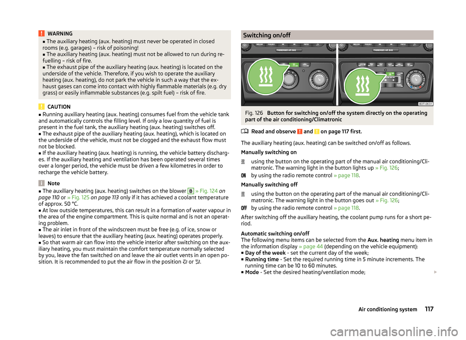
Switching on/offFig. 126
Button for switching on/off the system directly on the operating
part of the air conditioning/Climatronic
Read and observe
and on page 117 first.
The auxiliary heating (aux. heating) can be switched on/off as follows.
Manually switching on using the button on the operating part of the manual air conditioning/Cli-
matronic. The warning light in the button lights up » Fig. 126;
by using the radio remote control » page 118.
Manually switching off using the button on the operating part of the manual air conditioning/Cli-
matronic. The warning light in the button goes out » Fig. 126;
by using the radio remote control » page 118.
After switching off the auxiliary heating, the coolant pump runs for a short pe-
riod.
Automatic switching on/off
The following menu items can be selected from the Aux. heating menu item in
the information display » page 44 (depending on the vehicle equipment):
■ Day of the week - set the current day of the week;
■ Running time - Set the required running time in 5 minute increments. The
running time can be 10 to 60 minutes.
■ Mode - Set the desired heating/ventilation mode;
117Air conditioning system
Page 120 of 246
■Starting time 1 , Starting time 2 , Starting time 3 - for each pre-set time, the
day and the time (hour and minute) can be set for switching on the auxiliary
heating and ventilation. An empty position can be found between Sunday
and Monday when selecting the day. If this empty position is selected, the
activation is performed without taking into account the day.
■ Activate - Activate pre-set mode;
■ Deactivate - Deactivate pre-set mode;
■ Factory setting - Restore factory setting;
■ Back - Return to main menu
Only one programmed pre-set time can be active.
The last programmed pre-set time remains active.
After the auxiliary heating (aux. heating) automatically activates at the set
time, it is necessary to pre-set a time again.
If the menu item Back is selected or no changes are made on the display for
longer than 10 seconds, the set values are stored, but the pre-set time is not
activated.
The system switches itself off at the end of the running time set under the
menu item Running time .
Note
An indicator light on the button » Fig. 126 is illuminated when the system is
running.
Radio remote control
Fig. 127
Auxiliary heating (aux. heating):
Radio remote control
Read and observe and on page 117 first.
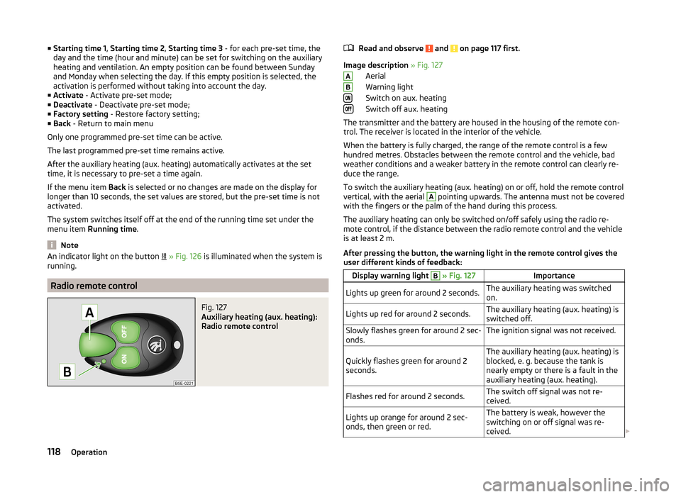
Image description » Fig. 127
Aerial
Warning light
Switch on aux. heating
Switch off aux. heating
The transmitter and the battery are housed in the housing of the remote con-
trol. The receiver is located in the interior of the vehicle.
When the battery is fully charged, the range of the remote control is a few
hundred metres. Obstacles between the remote control and the vehicle, bad
weather conditions and a weaker battery in the remote control can clearly re-
duce the range.
To switch the auxiliary heating (aux. heating) on or off, hold the remote control
vertical, with the aerial
A
pointing upwards. The antenna must not be covered
with the fingers or the palm of the hand during this process.
The auxiliary heating can only be switched on/off safely using the radio re-
mote control, if the distance between the radio remote control and the vehicle
is at least 2 m.
After pressing the button, the warning light in the remote control gives the
user different kinds of feedback:
Display warning light B » Fig. 127ImportanceLights up green for around 2 seconds.The auxiliary heating was switched
on.Lights up red for around 2 seconds.The auxiliary heating (aux. heating) is
switched off.Slowly flashes green for around 2 sec-
onds.The ignition signal was not received.Quickly flashes green for around 2
seconds.The auxiliary heating (aux. heating) is
blocked, e. g. because the tank is
nearly empty or there is a fault in the
auxiliary heating (aux. heating).Flashes red for around 2 seconds.The switch off signal was not re-
ceived.Lights up orange for around 2 sec-
onds, then green or red.The battery is weak, however the
switching on or off signal was re-
ceived. AB118Operation
Page 121 of 246
Display warning light B » Fig. 127ImportanceLights up orange for around 2 sec-
onds, then flashes green or red.The battery is weak, however the
switching on or off signal was not re-
ceived.Flashes orange for around 5 seconds.The battery is discharged, however
the switching on or off signal was not
received.
Replace the battery » page 211.
CAUTION
The radio remote control comprises electronic components and must therefore
be protected against water, severe impacts and direct sunlight.Communication and multimedia
General information
Introduction
This chapter contains information on the following subjects:
Mobile phones and two-way radio systems
119
Universal telephone preinstallation (hands free)
120
Operating the phone on the multifunction steering wheel
120
Symbols in the MAXI DOT display
121
Phone Phonebook
121
Mobile phones and two-way radio systems
ŠKODA permits the operation of mobile phones and two-way radio systems
with a professionally installed external aerial and a maximum transmission
power of up to 10 watts.
Please ask at a specialist workshop about installing and operating mobile
phones and two-way radio systems that have a transmission power of more
than 10 W.
Operating mobile phones or two-way radio systems may interfere with the
functionality of the electronic systems in your vehicle.
This could be for the following reasons.
› no external aerial.
› external aerial incorrectly installed.
› transmission power greater than 10 watts.
WARNING■
If a mobile phone or a two-way radio system is operated in a vehicle with-
out an external aerial or an external aerial which has been installed incor-
rectly, this can increase the strength of the electromagnetic field inside the
vehicle.■
Two-way radio systems, mobile phones or mounts must not be installed
on airbag covers or within the immediate deployment range of the airbags.
119Communication and multimedia