engine overheat SKODA SUPERB 2014 2.G / (B6/3T) Owner's Manual
[x] Cancel search | Manufacturer: SKODA, Model Year: 2014, Model line: SUPERB, Model: SKODA SUPERB 2014 2.G / (B6/3T)Pages: 246, PDF Size: 17.16 MB
Page 31 of 246
Revolutions counterRead and observe
on page 28 first.
The red scale of the revolution counter
1
» Fig. 20 on page 28 indicates the
range in which the system begins to limit the engine speed. The system auto-
matically restricts the engine speed to a steady limit.
You should shift into the next higher gear before the red scale of the revolu-
tion counter is reached, or select mode D on the automatic gearbox.
Follow the recommended gear to prevent engine speeds that are too high or too low » page 40 .
Speedometer
Read and observe
on page 28 first.
Warning against excessive speeds
An audible warning signal will sound when the vehicle speed exceeds 120 km/
h 1)
. The audible warning signal is switched off when the vehicle speed falls be-
low 120 km/h.
Coolant temperature gauge
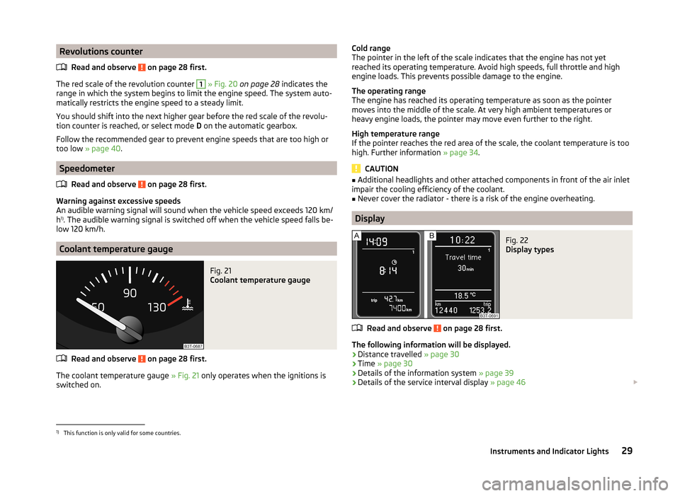
Fig. 21
Coolant temperature gauge
Read and observe on page 28 first.
The coolant temperature gauge » Fig. 21 only operates when the ignitions is
switched on.
Cold range
The pointer in the left of the scale indicates that the engine has not yet
reached its operating temperature. Avoid high speeds, full throttle and high
engine loads. This prevents possible damage to the engine.
The operating range
The engine has reached its operating temperature as soon as the pointer
moves into the middle of the scale. At very high ambient temperatures or
heavy engine loads, the pointer may move even further to the right.
High temperature range
If the pointer reaches the red area of the scale, the coolant temperature is too high. Further information » page 34.
CAUTION
■
Additional headlights and other attached components in front of the air inlet
impair the cooling efficiency of the coolant.■
Never cover the radiator - there is a risk of the engine overheating.
Display
Fig. 22
Display types
Read and observe on page 28 first.
The following information will be displayed.
› Distance travelled
» page 30
› Time
» page 30
› Details of the information system
» page 39
› Details of the service interval display
» page 46
1)
This function is only valid for some countries.
29Instruments and Indicator Lights
Page 34 of 246
The following message is shown in the MAXI DOT display.Gearbox overheated. Stop! Log book!
do not continue to drive! Stop the vehicle, switch off the engine, and wait
until the
icon goes out – risk of gearbox damage! You can continue your
journey as soon as the symbol disappears.WARNINGIf you have to stop for technical reasons, then park the vehicle at a safe
distance from the traffic, switch off the engine and activate the hazard
warning lights system » page 70. The warning triangle must be set up at
the prescribed distance - observe the national legal provisions when doing
so.
Note
■ If the MAXI DOT display shows warning messages, these messages must be
confirmed in order to access the main menu » page 40 .■
As long as the operational faults are not rectified, the symbols are always in-
dicated again. After they are displayed for the first time, the symbols continue
to be indicated without any extra messages for the driver.
Warning lights
Introduction
This chapter contains information on the following subjects:
Handbrake
33
Brake system
33
Seat belt warning light
33
Generator
33
Door open
34
Engine oil pressure
34
Coolant
34
Bonnet
34
Boot lid
34
Power steering / steering lock (system KESSY)
34
Engine oil level
35
Traction Control System (ASR)
35
Electronic Stability Control (ESC)
35 Antilock brake system (ABS)36 Rear fog light36
Lamp failure
36
Adaptive headlights (AFS)
36
Exhaust inspection system
36
Glow plug system (diesel engine)
36
Engine performance check (petrol engine)
37
Diesel particulate filter (diesel engine)
37
Fuel reserve
37
Airbag system
38
Tyre inflation pressure
38
Windscreen washer fluid level
38
Pads
38
Turn signal system
38
Low beam
39
Fog lights
39
Cruise control system
39
Selector lever lock / starter (system KESSY)
39
Main beam
39
The warning lights indicate certain functions or faults.
Some warning lights can be accompanied by acoustic signals and messages in
the display of the instrument cluster.
After switching on the ignition, some warning lights illuminate briefly as a
function test.
If the tested systems are OK, the corresponding warning lights go out a few
seconds after switching on the ignition or after starting the engine.
32Operation
Page 36 of 246
Door openRead and observe
on page 33 first.
The indicator light
illuminates if one or several doors are opened.
Engine oil pressure
Read and observe
on page 33 first.
When the warning light is flashing
, the engine oil pressure is too low.
The following message is shown in the MAXI DOT display. Oil pressure: Log book!
›
Stop the vehicle, switch off the engine, and check the engine oil lev-
el » page 186 .
If the warning light flashes,
do not drive any further , even if the oil level is
correct! Also do not leave the engine running at an idling speed.
Seek help from a specialist garage.
Coolant
Read and observe
on page 33 first.
If the warning light
lights up or flashes , either the coolant temperature is
too high or the coolant level is too low.
The following message is shown in the MAXI DOT display. Check coolant! Log book!
›
Stop the vehicle, switch off the engine, and check the coolant lev-
el » page 188 .
›
If the coolant level is too low, add coolant to the reservoir » page 188.
If the indicator light
does not illuminate after adding coolant and switching
on the ignition, you may continue your journey.
If the coolant level is within the specified range and the indicator light is still
illuminated, then there may be a malfunction of the cooling fan.
›
Check the fuse for the radiator fan, replace if necessary » page 217, Fuses in
the engine compartment .
If the coolant level and fan fuse are both OK but the indicator light is still
illuminated , do not continue your journey!
Seek help from a specialist garage.WARNING■ Carefully open the coolant expansion bottle. If the engine is hot, the cool-
ing system is pressurized - risk of scalding! It is therefore best to allow the
engine to cool down before removing the cap.■
Do not touch the radiator fan. The radiator fan may switch itself on auto-
matically even if the ignition is off.
CAUTION
■ Additional headlights and other attached components in front of the air inlet
impair the cooling efficiency of the coolant.■
Never cover the radiator - there is a risk of the engine overheating.
Bonnet
Read and observe
on page 33 first.
The indicator light
illuminates if the bonnet is unlocked.
Boot lid
Read and observe
on page 33 first.
The indicator light
illuminates if the boot lid is opened.
Power steering / steering lock (system KESSY)
Read and observe
on page 33 first.
Power steering
If the indicator light
illuminates , this indicates a partial failure of the power
steering and the steering forces can be greater.
If the indicator light
illuminates , this indicates a complete failure of the
power steering and the steering assist has failed (significantly higher steering
forces).
›
Stop the car, turn the ignition off and on again.
The powered steering is fully functional again if the
or
warning light does
not illuminate after you switch the engine back on.
34Operation
Page 142 of 246
Emergency ignition shutoff systemRead and observe
and on page 137 first.
The ignition can be turned off in an emergency even when travelling at a
speed of more than 2 km / hr.
›
Press the starter button » Fig. 134 on page 138 for longer than 1 second or
twice within 1 second.
After emergency stop of the ignition, the steering is unlocked.
Brakes
Introduction
This chapter contains information on the following subjects:
Information on braking
140
Handbrake
141WARNING■ Greater physical effort is required for braking when the engine is switch-
ed off – risk of accident!■
The clutch pedal must be actuated when braking on a vehicle with man-
ual transmission, when the vehicle is in gear and at low revs. Otherwise,
the function of the brake booster may be impaired – risk of accident!
■
When leaving the vehicle, never leave persons who might, for example,
release the handbrake or take the vehicle out of gear unattended in the ve-
hicle. The vehicle could then start to move – risk of accident!
WARNINGIn the case of damage to the standard fitted front spoiler or if retrofitting
another front spoiler, hub caps etc. » page 169, Services, modifications,
and technical alterations , make sure that the air supply to the front brakes
is not affected. The front brakes may overheat, which can have a negative
impact on the functioning of the braking system – risk of accident!
CAUTION
■ Observe the recommendations on the new brake pads » page 145.■Never let the brakes slip with light pressure on the pedal if braking is not
necessary. This causes the brakes to overheat and can also result in a longer
braking distance and excessive wear.Information on braking
Read and observe
and on page 140 first.
If the brakes are applied in full and the control unit for the braking system con-siders the situation to be dangerous for the following traffic, the brake light
flashes automatically.
After the speed was reduced below around 10 km/h or the vehicle was stop-
ped, the brake light stops flashing and the hazard warning light system
switches on. The hazard warning light system is switched off automatically af- ter accelerating or driving off again.
Before travelling a long distance with a steep gradient, reduce speed and shift
into the next lowest gear. As a result, the braking effect of the engine will be
used, reducing the load on the brakes. Any additional braking should be com-
pleted intermittently, not continuously.
Wear-and-tear
The wear of the brake pads is dependent on the operating conditions and driv-
ing style.
The brake pads wear more quickly if a lot of journeys are completed in towns
and over short distances or if a very sporty style of driving is adopted.
Under these severe conditions , the thickness of the brake pads must also be
checked by a specialist garage between service intervals.
Wet roads or road salt
The performance of the brakes can be delayed as the brake discs and brake
pads may be moist or have a coating of ice or layer of salt on them in winter.
The brakes are cleaned and dried by applying the brakes several times.
Corrosion
Corrosion on the brake discs and dirt on the bake pads occur if the vehicle has been parked for a long period and if you do not make much use of the braking
system. The brakes are cleaned and dried by applying the brakes several times.
Faults in the brake surface
If it is found that the braking distance has suddenly become longer and that
the brake pedal can be depressed further, the brake system may be faulty.
Visit a specialist garage immediately and adjust your style of driving appropri-
ately, as you will not know the exact extent of the damage.
140Driving
Page 143 of 246
Low brake fluid level
An insufficient level of brake fluid may result in problems in the brake system.
The level of the brake fluid is monitored electronically » page 33,
Brake sys-
tem .
Brake booster
The brake booster increases the pressure generated with the brake pedal. The
brake booster only operates when the engine is running.
Handbrake
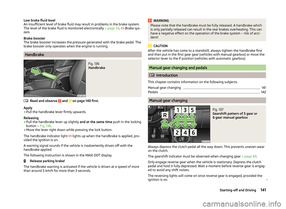
Fig. 136
Handbrake
Read and observe and on page 140 first.
Apply
›
Pull the handbrake lever firmly upwards.
Releasing
›
Pull the handbrake lever up slightly and at the same time push in the locking
button » Fig. 136 .
›
Move the lever right down while pressing the lock button.
The handbrake indicator light lights up when the handbrake is applied, pro-
vided the ignition is on.
A warning signal sounds if the vehicle is inadvertently driven off with the
handbrake applied.
The following instruction is shown in the MAXI DOT display. Release parking brake!
The handbrake warning is activated if the vehicle is driven at a speed of more
than around 5 km/h for more than 3 seconds.
WARNINGPlease note that the handbrake must be fully released. A handbrake which
is only partially released can result in the rear brakes overheating. This can
have a negative effect on the operation of the brake system – risk of acci-
dent!
CAUTION
After the vehicle has come to a standstill, always tighten the handbrake first
and then put in the first gear gear (vehicles with manual gearbox) or move the
selector lever to the P position (vehicles with automatic gearbox).
Manual gear changing and pedals
Introduction
This chapter contains information on the following subjects:
Manual gear changing
141
Pedals
142
Manual gear changing
Fig. 137
Gearshift pattern of 5 gear or
6 gear manual gearbox
Always depress the clutch pedal all the way down. This prevents uneven wear on the clutch.
The gearshift indicator must be observed when changing gear » page 40.
Only engage reverse gear when the vehicle is stationary. Depress the clutch
pedal and hold it fully depressed. Wait a moment before reverse gear is engag-
ed to avoid any shift noises.
The reversing lights will come on once reverse gear is engaged, provided the
ignition is on.
141Starting-off and Driving
Page 147 of 246
Indications of an activated emergency programme include the following:
› Only certain gears are selected.
› The reverse gear
R cannot be used.
› Shifting gears in Tiptronic mode is not possible.
Gearbox overheating The gearbox may, for example, become too hot due to frequent repeated
starting or stop-and-go traffic. Overheating is indicated by the warning
light » page 31 ,
Clutches of the automatic DSG gearbox are too hot .
Defective selector lever lock
If the selector lever lock is defective or its power supply is interrupted (e.g. dis-
charged vehicle battery, faulty fuse), the selector lever can no longer be moved
out of position P in the normal manner, and the vehicle can no longer be driv-
en. The selector lever must be unlocked specially » page 213.
Note
If the gearbox has switched to the emergency programme, visit a specialist ga-
rage.
Running in
Introduction
This chapter contains information on the following subjects:
New engine
145
New tyres
145
New brake pads
145
New engine
The engine has to be run in during the first 1 500 kilometres.
Up to 1 000 kilometres
›
Do not drive faster than 3/4 of the maximum speed of the gear in use, i.e. 3/4
of the maximum permissible engine speed.
›
No full throttle.
›
Avoid high engine speeds.
›
Do not tow a trailer.
From 1 000 up to 1 500 kilometres
Gradually increase the power output of the engine up to the full speed of the
gear engaged, i.e. up to the maximum permissible engine speed.
The red scale of the rev counter indicates the range in which the system be-
gins to limit the engine speed.
During the first operating hours the engine has higher internal friction than
later until all of the moving parts have harmonized. The driving style which you
adopt during the first approx.1 500 kilometres plays a decisive part in the suc-
cess of running in your car.
Never drive at unnecessarily high engine speeds even after the running-in pe-
riod.
On vehicles fitted with a manual gearbox, at the very latest shift up into the
next gear when the red area is reached. Observe the recommended
gear » page 40 , Gear recommendation . Very high engine speeds when acceler-
ating (accelerator) are automatically restricted »
.
In vehicles with manual transmission, do not drive at unnecessarily low engine
speeds. Shift down a gear when the engine is no longer running smoothly. Ob-
serve the recommended gear » page 40, Gear recommendation .
CAUTION
■
The engine is not protected from excessive engine revs caused by shifting
down at the wrong time. This can result in a sudden increase in revs beyond
the permissible maximum rpm, thereby causing engine damage.■
Never rev up a cold engine when the vehicle is stationary or when driving in
individual gears.
For the sake of the environment
Do not drive at unnecessarily high engine speeds. Shifting up sooner helps
save fuel, reduces engine noise and protects the environment.
New tyres
New tyres must firstly be “run in”, as they do not offer optimal grip at first.
Therefore, drive especially carefully for the first 500 km or so.
New brake pads
New brake pads do not initially provide optimal braking performance. They first
need to be “run in”. Therefore, drive especially carefully for the first 200 km or
so.
145Starting-off and Driving
Page 169 of 246
WARNING■Do not exceed the maximum permissible axle and drawbar load and the
maximum permissible total or towed weight of the vehicle and the trailer –
risk of accident and serious injury.■
Slipping loads can significantly impair the stability and safety of the vehi-
cle/trailer combination – risk of accident and serious injury.
Driving with a trailer
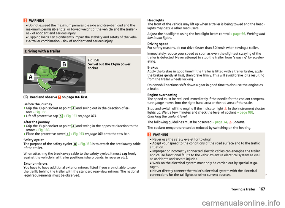
Fig. 158
Swivel out the 13-pin power
socket
Read and observe on page 166 first.
Before the journey
›
Grip the 13-pin socket at point
A
and swing out in the direction of ar-
row » Fig. 158 .
›
Lift off protective cap
5
» Fig. 153 on page 163 .
After the journey
›
Grip the 13-pin socket at point
A
and swing in the opposite direction to the
arrow » Fig. 158 .
›
Place the protective cover
5
» Fig. 153 on page 163 onto the tow bar.
Safety eyelet
The purpose of the safety eyelet
B
» Fig. 158 is to attach the breakaway cable
of the trailer.
When attaching the breakaway cable to the safety eyelet, it must sag freely
against the vehicle in all trailer positions (sharp bends, in reverse etc.).
Exterior mirrors
You have to have additional exterior mirrors fitted if you are not able to see
the traffic behind the trailer with the standard rear-view mirrors. The national
legal requirements must be observed.
Headlights
The front of the vehicle may lift up when a trailer is being towed and the head-
lights may dazzle other road users.
Adjust the headlights using the headlight beam control » page 66, Parking and
low beam lights .
Driving speed
For safety reasons, do not drive faster than 80 km/h when towing a trailer.
Immediately reduce your speed as soon as even the slightest swaying of the
trailer is detected. Never attempt to stop the trailer from “swaying” by acceler-
ating.
Brakes
Apply the brakes in good time! If the trailer is fitted with a trailer brake, apply
the brakes gently at first, then brake firmly. This will avoid brake jolts resulting
from the trailer wheels locking.
On downhill sections shift down a gear in good time to also use the engine as
a brake.
Engine overheating
The speed must be reduced immediately if the needle for the coolant tempera-
ture gauge moves into the right-hand area or the red area of the scale.
Stop and switch off the engine if the indicator light in the instrument cluster
lights up. Wait a few minutes and check the level of coolant » page 188,
Checking the coolant level .
The following guidelines must be observed » page 34,
Coolant
.
The coolant temperature can be reduced by switching on the heating.WARNING■ Never use the safety eyelet for towing!■Adapt your speed to the conditions of the road surface and to the traffic
situation.■
Improper or incorrectly connected electric cables can energise the trailer
and cause functional faults to the vehicle's entire electrical system as well
as accidents and severe injuries.
■
Work on the electrical system must only be carried out by specialist ga-
rages.
■
Never directly connect the trailer's electrical system with the electrical
connections for the tail lights or other current sources.
167Towing a trailer
Page 189 of 246
ReplenishingRead and observe
and on page 185 first.
›
Check the oil level » page 186.
›
Unscrew the cap of the engine oil filler opening » Fig. 161 on page 184 .
›
Replenish the oil in portions of 0.5 litres in accordance with the correct speci-
fications » page 185 .
›
Check the oil level » page 186.
›
Carefully screw on the oil filler opening cap and push the dipstick in fully.
Changing
Read and observe
and on page 185 first.
The engine oil must be changed according to prescribed service intervals or ac-
cording to the service interval display » Service plan .
Coolant
Introduction
This chapter contains information on the following subjects:
Capacity
188
Checking the coolant level
188
Replenishing
188
The coolant consists of water with coolant additive. This mixture guarantees
antifreeze protection, protects the cooling/heater system against corrosion
and prevents lime formation.
Vehicles exported to countries with a mild climate are already factory-filled
with a coolant which offers antifreeze protection down to about -25 ℃. In
these countries, the concentration of coolant additive should be at least 40%.
Vehicles exported to countries with a cold climate are already factory-filled
with a coolant which offers antifreeze protection down to about -35 °C. In
these countries, the concentration of coolant additive should be at least 50%.
If a higher concentration of antifreeze is required for climatic reasons, the con-
centration of coolant additive can be increased up to a maximum of 60% (anti-
freeze protection down to approx. -40 °C).
When refilling, only use the same antifreeze identified on the coolant expan-
sion vessel » Fig. 164 on page 188 .WARNING■
The engine compartment of your car is a hazardous area. The following
warning instructions must be followed at all times when working in the en-
gine compartment » page 182.■
Do not continue your journey if for some reason it is not possible to fill
with coolant under the current circumstances
. Switch off the engine and
seek assistance from a specialist garage.
CAUTION
■ The concentration of coolant additive in the coolant must never be under
40%.■
Over 60% of coolant additive in the coolant reduces the antifreeze protec-
tion and cooling effect.
■
A coolant additive that does not comply with the correct specifications can
significantly reduce the corrosion protection.
■
Any faults resulting from corrosion may cause a loss of coolant and can con-
sequently result in major engine damage!
■
Do not fill the coolant above the mark
A
» Fig. 164 on page 188 .
■
If a fault causes the engine to overheat, we recommend visiting a specialist
garage, as otherwise serious engine damage may occur.
■
Additional headlights and other attached components in front of the air inlet
impair the cooling efficiency of the coolant.
■
Never cover the radiator - there is a risk of the engine overheating.
187Inspecting and replenishing
Page 208 of 246
›Do not remove the foreign body, e.g. screw or nail, from the tyre.›Unscrew the valve cap.›
Use the valve remover
1
to unscrew the valve core and place it on a clean
surface (rag, paper, etc.).
Sealing and inflating the tyre
Read and observe
on page 205 first.
Sealing
›
Shake the tyre inflator bottle
10
» Fig. 181 on page 205 vigorously several
times.
›
Firmly screw the inflation hose
3
onto the tyre inflator bottle
10
in a clock-
wise direction. The film on the cap is pierced automatically.
›
Remove the plug from the inflation hose
3
and plug the open end fully onto
the tyre valve.
›
Hold the bottle
10
with the bottom facing upwards and fill all of the sealing
agent from the tyre inflator bottle into the tyre.
›
Remove the empty tyre inflator bottle from the valve.
›
Screw the valve core back into the tyre valve using the valve remover
1
.
Inflating
›
Screw the air compressor tyre inflation hose
5
» Fig. 181 on page 205 firmly
onto the tyre valve.
›
Check that the air release valve
7
is closed.
›
Start the engine and run it in idle.
›
Plug the connector
9
into 12 Volt socket » page 89, Cigarette lighter .
›
Switch on the air compressor with the ON and OFF switch
8
.
›
Allow the air compressor to run until a pressure of 2.0 - 2.5 bar is achieved.
Maximum run time of 8 minutes »
›
Switch off the air compressor.
›
If you cannot reach an air pressure of 2.0 – 2.5 bar, unscrew the tyre inflation
hose
5
from the tyre valve.
›
Drive the vehicle 10 metres forwards or backwards to allow the sealing agent
to “distribute” in the tyre.
›
Firmly screw the tyre inflation hose
5
back onto the tyre valve and repeat
the inflation process.
›
If you cannot reach the required tyre inflation pressure here either, this
means the tyre has sustained too much damage. You cannot seal with tyre with the breakdown kit »
.
›
Switch off the air compressor.
›
Remove the tyre inflation hose
5
from the tyre valve.
Once a tyre inflation pressure of 2.0 – 2.5 bar is reached, continue the journey
at a maximum speed of 80 km/h (50 mph).
Check the tyre inflation pressure after driving for 10 minutes » page 206.WARNING■
The tyre inflation hose and air compressor may get hot as the tyre is be-
ing inflated – there is a risk of injury.■
Do not place the hot tyre inflation hose or hot air compressor on flamma-
ble materials – there is a risk of fire.
■
If you cannot inflate the tyre to at least 2.0 bar, this means the damage
sustained was too serious. The sealing agent cannot be used to seal the
tyre.
Do not drive the vehicle. Seek help from a specialist garage.
CAUTION
Switch off the air compressor after running 8 minutes at the latest – there is a
risk of overheating. Allow the air compressor to cool a few minutes before
switching it on again.
Check after 10 minutes' driving
Read and observe
on page 205 first.
Check the tyre inflation pressure after driving for 10 minutes!
If the tyre pressure is 1.3 bar or less
›
Do not drive the vehicle! You cannot properly seal with tyre with the
breakdown kit.
If the tyre pressure is 1.3 bar or more
›
Adjust the tyre inflation pressure to the correct value (see inside of fuel filler
cap).
›
Continue driving carefully to the nearest specialist garage at a maximum speed of 80 km/h (50 mph).
206Do-it-yourself