winter tyres SKODA SUPERB 2014 2.G / (B6/3T) Owner's Manual
[x] Cancel search | Manufacturer: SKODA, Model Year: 2014, Model line: SUPERB, Model: SKODA SUPERB 2014 2.G / (B6/3T)Pages: 246, PDF Size: 17.16 MB
Page 6 of 246
Inspecting and replenishing179Fuel179
Engine compartment
182
Engine oil
185
Coolant
187
Brake fluid
189
Vehicle battery
189
Wheels
193
Tyres and wheel rims
193
Winter operation
198
Do-it-yourself
Emergency equipment and self-help
200
Emergency equipment
200
Changing a wheel
201
Tyre repair
204
Jump-starting
207
Towing the vehicle
208
Radio remote control
210
Emergency unlocking/locking
212
Emergency operation of the sliding/tilting
roof
213
Replacing windscreen wiper blades
214
Fuses and light bulbs
215
Fuses
215
Bulbs
219
Technical data
Technical data
224
Vehicle data
224
Index
4Table of Contents
Page 47 of 246
SettingsRead and observe
and on page 44 first.
You can change certain settings by means of the MAXI DOT display. The cur-
rent menu item is shown in the top of the display under a line.
The following information can be selected (depending on the equipment in- stalled in the vehicle).
Language
You can set the language for the display texts here.
Automatic blind (Combi)
This is where the automatic roll-up function of the boot roll cover can be deac-
tivated/activated when opening the boot lid.
MFD displays
Activate or deactivate certain displays of the multifunction display here.
Comfort
The following functions can be activated, deactivated or adjusted here:
Rain closing
Activate/deactivate the function for automatically
closing the window and the tilt/slide sunroof in a
locked vehicle when it starts raining a)
. If the function
is activated and it is not raining, the windows includ-
ing the panoramic tilt/slide sunroof will close auto-
matically after approx. 12 hours.ATA confirmSwitch on/off the audible signal indicating activation
of the anti-theft alarm system. Further informa-
tion » page 54 .Central lockingSwitch on/off the central locking and automatic lock-
ing function, also applies to the KESSY system. Fur-
ther information » page 52, Individual settings .
Window op.
Only convenience mode for the driver window or for
all of the windows can be adjusted here. Further in-
formation » page 61, Window convenience opera-
tion .
Mirror down
Activate/deactivate the function for mirror lowering
on the front passenger side when in the reverse
gear b)
. Further information » page 78, Fold in pas-
senger's mirror .
Mirror adjust.
Activation / deactivation of the synchronous exterior
mirror function settings. Further informa-
tion » page 78 , Synchronous adjustment of the mir-
ror .Factory settingRestore the Convenience factory setting.a)
This function is only available on vehicles with a rain sensor.
b)
This function is only available on vehicles with an electrically adjustable driver seat.
Lights and Visibility
The following functions can be activated, deactivated or adjusted here:
Coming HomeActivate/deactivate and adjust the light duration of
the COMING HOME function. Further informa-
tion » page 70 .Leaving HomeSwitch on/off and adjust the light duration of the
LEAVING HOME function. Further informa-
tion » page 70 .Footwell lightActivate/deactivate and adjust the footwell light in-
tensity.Daytime running lightsActivate/deactivate “DAY LIGHT” function. Further in-
formation » page 67, Daylight running lights (DAY
LIGHT) .Rear wiperActivate/deactivate the function of the automatic
rear window wiping. Further information » page 76,
Automatic rear window wiper (Superb Combi) .Lane ch. flashActivate/deactivate the lane ch. flash function. Fur-
ther information » page 67.Travel modeActivate/deactivate the travel mode feature. Further
information » page 69, Tourist lights (Travel mode) .Factory settingRestore the factory setting for the lighting.
Time
The time, time format (12 or 24 hour indicator) and the changeover between
summer/winter time can be set here.
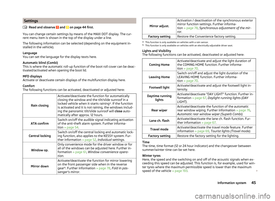
Winter tyres
Here, the speed and the switching on and off of the acoustic signals when ex-
ceeding this speed can be adjusted. This function is, for example, used for win-
ter tyres where the maximum permissible speed is lower than the maximum
speed of the vehicle » page 193.
45Information system
Page 48 of 246
As soon as the parking procedure is completed, an audible signal sounds and
the following message appears in the information display.
Winter tyres: maximum ... km/h.
Units of measurement
The units for the temperature, consumption and distance driven can be set
here.
Assistants
The tones of the audible signals for the parking aid can be adjusted here.
Alt. speed dis.
Here, the display of the second speed in mph 1)
can be activated.
Further information » page 31, Display of the second speed .
Service
The days and kilometres remaining until the next service can be displayed
here.
Further information » page 46, Service interval display .
Factory setting
The factory setting of the functions of the MAXI DOT display can be restored
here.
Compass point display
Read and observe
and on page 44 first.
For vehicles with a factory fitted navigation system, an abbreviation for eachpoint of the compass (depending on the current direction of travel) is shown
on the top left-hand corner of the display.
The compass point display only operates when the ignition is switched on.
Service interval display
Introduction
This chapter contains information on the following subjects:
Prompt in the MAXI DOT display
46
Prompt in the segment display
47
Resetting the service interval display
47
The service interval display shows the time and mileage to the next service
event.
The service due date is automatically displayed on the display and this infor-
mation can be displayed manually if necessary.
The kilometre indicator or the days indicator reduces in steps of 100 km or,
where applicable, days until the service due date is reached.
The information regarding the service intervals can be found in the service
schedule.
Note
Information is retained in the Service Interval Display even after the vehicle
battery is disconnected.
Prompt in the MAXI DOT display
Oil change service
If an oil change service is due, the following message appears: Oil change in …
km or … days.
As soon as the service interval date has been reached, the message Oil
change now! appears once the ignition has been switched on!
Inspection
If an inspection is due, the following message appears: Inspection in ... km
or ... days.
As soon as the service interval date has been reached, the message Inspec-
tion now! appears once the ignition has been switched on!
1)
For models with the speedometer in mph, the second speed is displayed in km/h.
46Operation
Page 64 of 246
Opening›Press the button on the remote control key.›
Hold the key in the driver's lock in the unlock position.
›
Press and hold the upper part of the central locking button in the driver's
door » page 52 .
›
Hold button
A
» Fig. 43 on page 60 in the opening position.
Closing
›
Press
button on the remote control key.
›
Hold the key in the driver's lock in the lock position.
›
Press and hold the lower part of the central locking button » page 52 in the
driver's door.
›
Hold button
A
» Fig. 43 on page 60 in the closing position.
›
In the KESSY system, hold a finger on the sensor
1
» Fig. 32 on page 50 .
The speed limit for winter tyres can be set in the MAXI DOT display in the
menu item Window op. . » page 45 .
The prerequisite for ensuring that the convenience operating feature correctly
is the automatic opening/closing of all windows is operational.
Convenience opening or closing the window using the key in the driver's lock
is only possible within 45 seconds after locking the vehicle.
The movement of the window is stopped immediately when the key or the re-
spective button is released.
Operational faults
Read and observe
and on page 60 first.
The automatic power windows do not work if the vehicle battery has been dis-connected and connected again while a window was open. The system must
be activated.
Activation sequence:
›
Switch on the ignition.
›
Pull the top edge of the button and close the window.
›
Release the button.
›
Pull the relevant button upwards again for approx. 3 seconds, and keep it
pressed down.
Electric sliding/tilting roof
Introduction
This chapter contains information on the following subjects:
Operation
62
Convenience operation of sliding / tilting roof
63
Electric sliding/tilting roof with solar cells
63
The electric sliding/tilting roof (abbreviated in the following as 'sliding/tilting
roof') can only be operated when the ignition is turned on and when the out-
door temperature is higher than -20 °C.
The sliding/tilting roof can still be operated for approx. 10 minutes after
switching the ignition off. However, as soon as the driver or front passenger's
door is opened it is no longer possible to operate the sliding/tilting roof.
CAUTION
■ Always close the sliding/tilting roof before disconnecting the battery.■If the battery has been disconnected and reconnected, it is possible that the
sliding/tilting roof does not operate correctly. In this case, turn the rotary
switch to the switch position A
» Fig. 45 on page 62 and push forward for
about 10 seconds.
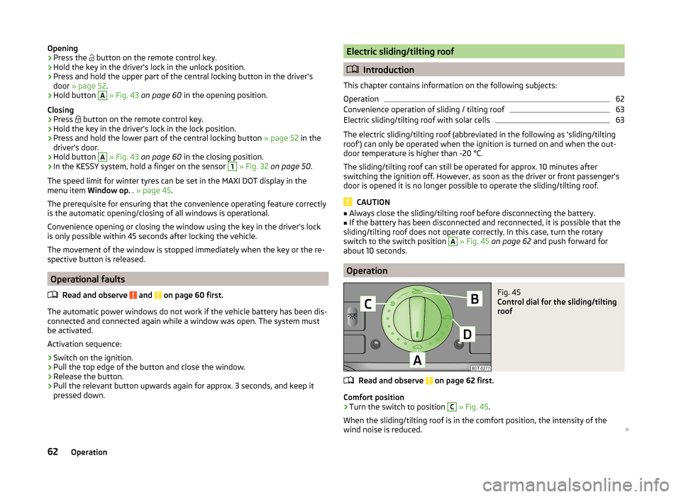
Operation
Fig. 45
Control dial for the sliding/tilting
roof
Read and observe on page 62 first.
Comfort position
›
Turn the switch to position
C
» Fig. 45 .
When the sliding/tilting roof is in the comfort position, the intensity of the
wind noise is reduced.
62Operation
Page 148 of 246
Economical driving and environmental sustainability
Introduction
This chapter contains information on the following subjects:
Looking ahead
146
Economical gear changing
146
Avoiding full throttle
147
Reducing idling
147
Avoiding short distances
147
Checking tyre inflation pressure
147
Avoiding unnecessary ballast
147
Regular maintenance
148
Saving electrical energy
148
Environmental compatibility
148
The technical requirements for low fuel usage and economic efficiency of the
vehicle have already been built into the vehicle at the works. ŠKODA places a
particular emphasis on minimising negative effects on the environment.
It is necessary to take note of the guidelines given in this chapter in order to make best use of these characteristics and to maintain their effectiveness.
Fuel consumption, environmental pollution and the wear to the engine, brakes
and tyres depend essentially on the following three factors:
› your personal driving style
› operating conditions
› technical requirements
The fuel economy by can be improved by 10 -15 % by always looking ahead and
driving in an economical way.
Fuel consumption is also be influenced by external factors which are beyond
the driver's control. Consumption increases during the winter or under difficult
conditions, on poor roads, etc.
Fuel consumption can vary considerably from the manufacturer's data, as a re-
sult of outside temperatures, the weather and driving style.
The optimal engine speed should be obtained when accelerating, in order to
avoid a high fuel consumption and resonance of the vehicle.
CAUTIONAll the speed and engine revolution figures apply only when the engine is at
its normal operating temperature.
Looking ahead
Read and observe
on page 146 first.
A vehicle's highest fuel consumption occurs when accelerating, therefore un-necessary accelerating and braking should be avoided. If looking ahead when
driving, less braking and consequently less accelerating are required.
If possible, let your vehicle coast to a stop, or use the engine brake, if you can see that the next set of traffic lights is on red, for example.
Economical gear changing
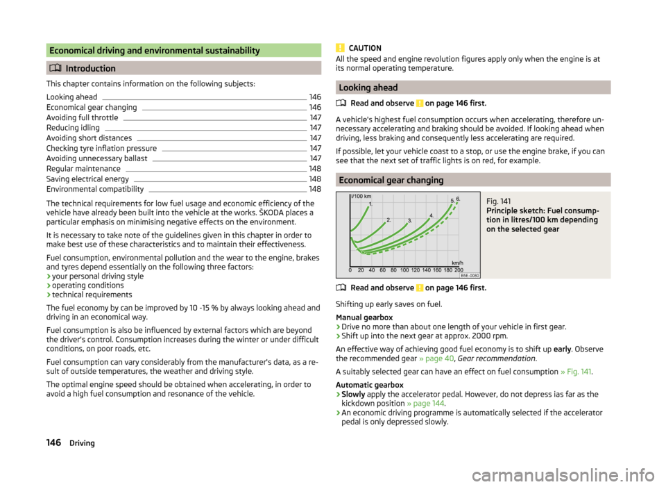
Fig. 141
Principle sketch: Fuel consump-
tion in litres/100 km depending
on the selected gear
Read and observe on page 146 first.
Shifting up early saves on fuel.
Manual gearbox › Drive no more than about one length of your vehicle in first gear.
› Shift up into the next gear at approx. 2000 rpm.
An effective way of achieving good fuel economy is to shift up early. Observe
the recommended gear » page 40, Gear recommendation .
A suitably selected gear can have an effect on fuel consumption » Fig. 141.
Automatic gearbox
› Slowly
apply the accelerator pedal. However, do not depress ias far as the
kickdown position » page 144.
› An economic driving programme is automatically selected if the accelerator
pedal is only depressed slowly.
146Driving
Page 197 of 246

Fig. 169
Replacing wheels
Read and observe and on page 193 first.
The service life of tyres depends on the inflation pressure, driving style and
other circumstances. Following the advice below can extend the service life of
your tyres.
Tyre pressure
Check the tyre pressure, including that of the spare wheel, at least once a
month and also before setting off on a long journey.
The tyre pressures for tyres are shown on the inside of the fuel filler
flap » Fig. 168 –
.
The tyre pressure should be at the highest pressure specified for your vehicle
at all times.
Always check the inflation pressure when the tyres are cold. Do not reduce the
higher pressure on warm tyres.
With greater additional load, adjust the tyre inflation pressure accordingly.
Driving style
Fast cornering, sharp acceleration and braking increase the wear of your tyres.
Balancing wheels
The wheels of a new vehicle are balanced. When driving, however, there are a
range of factors that may result in an imbalance. This may become apparent by
a “vibration” in the steering.
Have the wheels rebalanced after replacing the tyres.
Wheel alignment errors
Incorrect wheel alignment at the front or rear leads to excess wear of the
tyres.
Tyre damage
Drive over kerbs and other such obstacles slowly and at right angles wherever
possible in order to avoid damage to tyres and wheel trims.
We recommend checking your tyres and wheel rims for damage (punctures,
cuts, splits and bulges, etc.) on a regular basis. Remove foreign bodies (e.g.
small stones) from the tyre tread immediately.
Replacing wheels
If significantly greater wear is present on the front tyres, we recommend
swapping the front wheels with the rear wheels as shown in the dia-
gram » Fig. 169 . You will then obtain approximately the same life for all the
tyres.
We recommend that you swap the tyres every 10,000 km in order to achieve
even wear on all tyres and to ensure optimal service life for the tyres.
Storing tyres
Identify disassembled tyres so that the previous direction of rotation can be
maintained if the tyres are reassembled.
Always store wheels or tyres in a cool, dry place that is as dark as possible.
Tyres which are not fixed to a wheel trim should be stored upright.
Wear indicators
The base of the tread of the tyres has 1.6 mm high wear indicators installed.
These wear indicators are arranged evenly spaced around the circumference of
the tyre a number of times depending on the make » Fig. 168 -
. Markings on
the walls of the tyres through the letters “TWI”, triangular symbols or other
symbols identify the position of the wear indicators.
Tyre age
Tyres age and lose their original characteristics, even if they are not being
used. Therefore, we recommend not using summer or winter tyres older than
6 or 4 years old respectively.
New tyres
Read and observe
and on page 193 first.
Only use radial tyres of the same type, size (rolling circumference) and tread
pattern on one axle on all four wheels.
The tyre/wheel combinations which are approved for your vehicle are indica-
ted in your vehicle documents.
195Wheels
Page 199 of 246
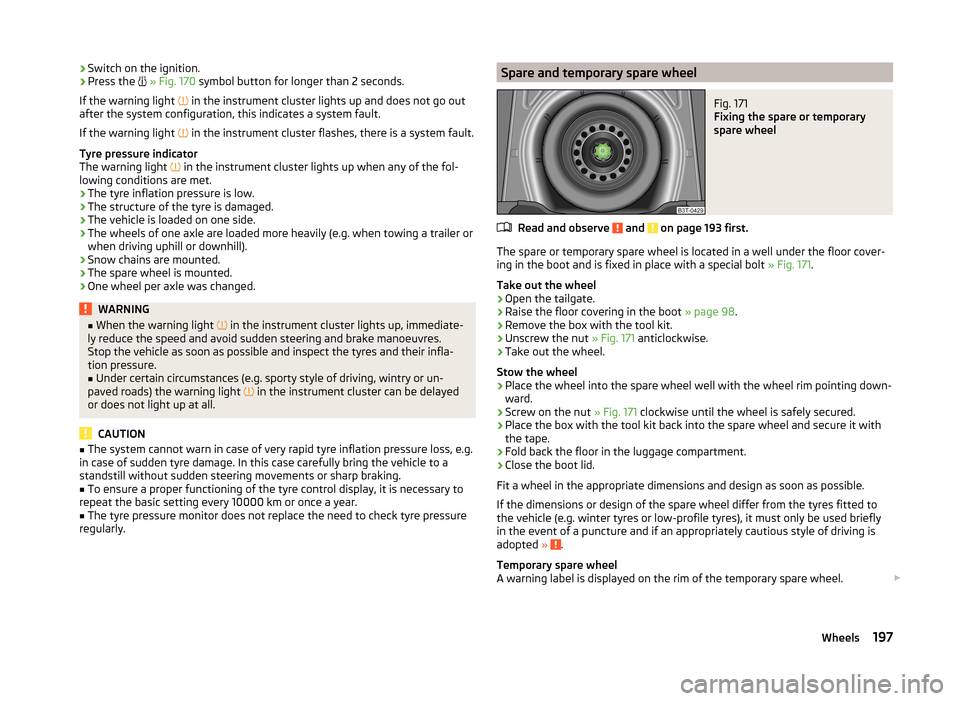
›Switch on the ignition.›Press the
» Fig. 170 symbol button for longer than 2 seconds.
If the warning light
in the instrument cluster lights up and does not go out
after the system configuration, this indicates a system fault.
If the warning light
in the instrument cluster flashes, there is a system fault.
Tyre pressure indicator
The warning light
in the instrument cluster lights up when any of the fol-
lowing conditions are met.
› The tyre inflation pressure is low.
› The structure of the tyre is damaged.
› The vehicle is loaded on one side.
› The wheels of one axle are loaded more heavily (e.g. when towing a trailer or
when driving uphill or downhill).
› Snow chains are mounted.
› The spare wheel is mounted.
› One wheel per axle was changed.WARNING■
When the warning light in the instrument cluster lights up, immediate-
ly reduce the speed and avoid sudden steering and brake manoeuvres.
Stop the vehicle as soon as possible and inspect the tyres and their infla-
tion pressure.■
Under certain circumstances (e.g. sporty style of driving, wintry or un-
paved roads) the warning light
in the instrument cluster can be delayed
or does not light up at all.
CAUTION
■ The system cannot warn in case of very rapid tyre inflation pressure loss, e.g.
in case of sudden tyre damage. In this case carefully bring the vehicle to a
standstill without sudden steering movements or sharp braking.■
To ensure a proper functioning of the tyre control display, it is necessary to
repeat the basic setting every 10000 km or once a year.
■
The tyre pressure monitor does not replace the need to check tyre pressure
regularly.
Spare and temporary spare wheelFig. 171
Fixing the spare or temporary
spare wheel
Read and observe and on page 193 first.
The spare or temporary spare wheel is located in a well under the floor cover-
ing in the boot and is fixed in place with a special bolt » Fig. 171.
Take out the wheel
›
Open the tailgate.
›
Raise the floor covering in the boot » page 98.
›
Remove the box with the tool kit.
›
Unscrew the nut » Fig. 171 anticlockwise.
›
Take out the wheel.
Stow the wheel
›
Place the wheel into the spare wheel well with the wheel rim pointing down-
ward.
›
Screw on the nut » Fig. 171 clockwise until the wheel is safely secured.
›
Place the box with the tool kit back into the spare wheel and secure it with
the tape.
›
Fold back the floor in the luggage compartment.
›
Close the boot lid.
Fit a wheel in the appropriate dimensions and design as soon as possible.
If the dimensions or design of the spare wheel differ from the tyres fitted to
the vehicle (e.g. winter tyres or low-profile tyres), it must only be used briefly
in the event of a puncture and if an appropriately cautious style of driving is
adopted »
.
Temporary spare wheel
A warning label is displayed on the rim of the temporary spare wheel.
197Wheels
Page 200 of 246
Please note the following if you intend to use the temporary spare wheel.› The warning label must not be covered after installing the wheel.
› Be particularly observant when driving.
› The temporary spare wheel is inflated to the maximum inflation pressure for
the vehicle » Fig. 168 on page 194 .
› The tyre inflation pressure of the spare wheel R 18 is 420 kPa.
› Only use this temporary spare wheel to reach the nearest specialist garage,
as it is not intended for long-term use.WARNING■ Never drive with more than one temporary spare wheel mounted!■Never use the temporary spare wheel if it is damaged.■
If the dimensions or design of the temporary spare wheel differ from the
fitted tyres, never drive faster than 80 km/h (or 50 mph).
■
Avoid accelerating at full throttle, sharp braking and fast cornering.
CAUTION
Observe the instructions on the warning sign of the temporary spare wheel.
Full wheel trim
Read and observe
and on page 193 first.
Pulling off
›
Hook the clamp found in the vehicle tool kit » page 201 into the reinforced
edge of the wheel trim.
›
Push the wheel wrench through the clamp, support on the tyre and pull off
the wheel trim.
Fitting
›
Press the wheel trim onto the wheel rim at the designated valve opening.
›
Then press the trim into the wheel rim until its entire circumference locks
correctly in place.
CAUTION
■ Use the pressure of your hand only, do not strike the full wheel trim. Avoid
heavy impacts when the trim has not yet been inserted into the wheel rim.
This could cause damage to the guide and centring elements of the trim.■
When using the anti-theft wheel bolt, ensure that it is in the hole in the
valve area » page 204 , Securing wheels against theft .
■
If wheel trims are retrofitted it must be ensured that an adequate flow of air
is assured to cool the brake system.
Wheel boltsFig. 172
Remove the cap
Read and observe and on page 193 first.
Pulling off
›
Push the extraction pliers » page 201 sufficiently far onto the cap until the
inner catches of the pliers are positioned at the collar of the cap.
›
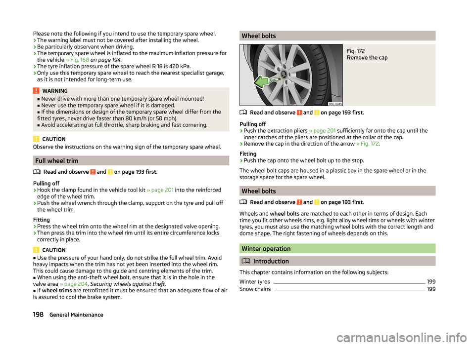
Remove the cap in the direction of the arrow » Fig. 172.
Fitting
›
Push the cap onto the wheel bolt up to the stop.
The wheel bolt caps are housed in a plastic box in the spare wheel or in the
storage space for the spare wheel.
Wheel bolts
Read and observe
and on page 193 first.
Wheels and wheel bolts are matched to each other in terms of design. Each
time you fit other wheels rims, e.g. light alloy wheel rims or wheels with winter
tyres, you must also use the matching wheel bolts with the correct length and
dome shape. The right fastening of wheels depends on this.
Winter operation
Introduction
This chapter contains information on the following subjects:
Winter tyres
199
Snow chains
199198General Maintenance
Page 201 of 246
Winter tyres
Fitting winter tyres will significantly improve the handling of your vehicle when
driving in wintry road conditions. Summer tyres have less grip on ice, snow and
at temperatures below 7 °C. This is especially true of vehicles fitted with wide
tyres or high-speed tyres .
In order to achieve the best possible handling properties, winter tyres must be
fitted on all 4 wheels, the minimum tread depth must be 4 mm and tyres must
be no older than 4 years.
Winter tyres of a lower speed category can be used provided that the permissi-
ble maximum speed of these tyres is not exceeded even if the possible maxi-
mum speed of the vehicle is higher.
The speed limit for winter tyres can be set in the MAXI DOT display in the
menu item Winter tyres » page 45 .
For the sake of the environment
Fit the summer tyres on again in good time as they provide better handling
properties, a shorter braking distance, less tyre noise, and reduced tyre wear
on roads which are free of snow and ice as well as at temperatures above 7 °C.
The fuel consumption is also lower.
Snow chains
When driving in wintry road conditions, snow chains improve not only traction,
but also the braking performance.
Snow chains must only be mounted on the front wheels.
For technical reasons, it is only permissible to fit snow chains with the follow-
ing wheel/tyre combinations.
Wheel sizeDepth (D)Tyre size7J x 16 a)45 mm205/556J x 16 a)50 mm205/556J x 1745 mm205/50a)
Not valid for vehicles with 3.6 l/191 kW FSI engine.
Only use fine-link snow chains . They must not project more than 9 mm - in-
cluding the chain lock.
CAUTION■ The chains must be removed when driving on roads which are free of snow.
They adversely affect the handling of your vehicle, damage the tyres and are
rapidly destroyed.■
Remove the full wheel trims » page 198 before fitting the snow chains.
199Wheels
Page 242 of 246
Door lock cylinders175
Headlight lenses175
High-pressure cleaner173
Plastic parts174
Polishing the paintwork174
Rubber seals174
Taking care of the interior176
Taking care of your vehicle exterior173
Washing172
Washing by hand172
Wash system173
Wax treatment174
Taking care of your vehicles Fabric covers
178
TCS Operation
152
Technical data224
Telephone122, 124
Temporary spare wheel197
Tilting roof see Electric sliding/tilting roof
62
Tiptronic143
Tools201
TOP TETHER24
Towing208
Towing a trailer163
Towing device Description
163
Drawbar load163
Use and care166
Towing eye Front
209
Rear210
Towing protection54
Traction Control System (TCS)152
Trailer163, 166
13-pin power socket167
driving with a trailer167
Loading166
Safety eye167
Trailer stabilisation168
Transport Luggage compartment
95
Roof rack system106
Transporting children safely21
TSA168
Turn signal67
Turn signal system Warning light
38
Twindoor see boot lid
55
Two-way radio systems119
Type plate224
Tyre inflation pressure Warning light
38
Tyre load-bearing capacity See Wheels
196
Tyre pressure monitor Setting
196
Tyre repair Check pressure
206
Preparations205
Sealing and inflating the tyre206
Tyres193
Inflation pressure194
New195
See Wheels195
Sizes194
Tyre wear indicator194
U
Umbrella Tray
93
Underbody protection176
Unleaded petrol150
Unlock Remote control
49
Vehicle key49
Unlocking Individual settings52
KESSY50
Unlocking and locking48
Useful equipment Ashtray
89
Car park ticket holder87
Cigarette lighter89
Clothes hook92
Cup holders88
Glasses storage box91
Removable ski bag95
Seat backrest with long-cargo channel94
Storage compartment in the front centre con- sole
88
Storage compartment on the driver's side87
Storage compartments in the doors88
Using the information system40
Using the selector lever142
V
Variable loading floor
102
Dividing the luggage compartment102
Remove102
slides off on aluminium rails103
Vehicle battery Automatic load deactivation
193
charging192
Checking the battery electrolyte level191
Cover191
Disconnecting and reconnecting192
Operation in winter191
Replace192
Safety instructions189
Vehicle care Alcantara
178
Artificial leather178
Cloths178
Vehicle Condition see Auto Check Control
31
240Index