buttons SKODA SUPERB 2015 3.G / (B8/3V) User Guide
[x] Cancel search | Manufacturer: SKODA, Model Year: 2015, Model line: SUPERB, Model: SKODA SUPERB 2015 3.G / (B8/3V)Pages: 276, PDF Size: 42.14 MB
Page 91 of 276

When the ignition is switched off, the seat heating and seat ventilation is also
switched off. If the engine is started again within 10 minutes, the driver's seat
heating and seat ventilation is automatically turned on again at the last set-
ting.WARNINGIf you have a subdued pain and/or temperature sensitivity, e.g. through
medication, paralysis or because of chronic illness (e.g. diabetes), we rec-
ommend not to use the seat heating. There may be difficult to heal burns. If
the seat heating is used, we recommend to make regular breaks in your
journey when driving long distances, so that the body can recuperate from
the stress of the journey. Please consult your doctor, who can evaluate
your specific condition.
CAUTION
The following instructions must be observed to avoid damage to the seats.■Do not kneel on the seats or otherwise apply concentrated pressure to them.■
Do not turn on any of the seat heaters if seats are not occupied.
■
Do not switch on the relevant seat heating if the seats have objects attached
to or placed on them, for example a child seat, a bag, etc.
■
When there are additional protective covers or protective covers mounted on
each of the seats, do not turn the seat heating on.
Note
If the on-board voltage decreases, the seat heating and ventilation switches
off automatically » page 216, Automatic load deactivation .
Front seats with heating
Read and observe
and on page 89 first.
The level of the seat heating is indicated by the number of illuminated warning
lights below the switch.
Seat heating operation
›
Press button or
.
The seat heating is switched on at maximum heat » Fig. 86 on page 88 -
.
With repeated pressing of the switch, the level is down-regulated up to the
switch-off.
Front seats with heating and ventilationFig. 87
Infotainment display: Front seat
heating and ventilation with
maximum heating / ventilation
level switched on
Read and observe and on page 89 first.
The heating / ventilation level is indicated by the number of illuminated func-
tion keys in Infotainment, if necessary, by the number of illuminated warning
lights below the button.
The heating / ventilation setting can also be adjusted in the Infotainment us-
ing function keys
A
and
B
» Fig. 87 and with the respective function key
turned off.
Seat heating operation only
›
Press button or
.
The seat heating is switched on at maximum heat » Fig. 86 on page 88 -
.
With repeated pressing of the switch, the level is down-regulated up to the
switch-off.
The heat output can be set in the Infotainment.
Only use seat ventilation
›
Press button or
.
›
Turn off the seat heating.
›
Set the ventilation level in the Infotainment with the function keys
A
» Fig. 87
.
Another setting of the ventilation level up to turn off can also take place by
pressing the buttons and
again.
Operating the seat heating and ventilation simultaneously
›
Press button or
.
›
Adjust the heating / ventilation level in the Infotainment.
Below the button the control lamps » Fig. 86 on page 88 -
illuminate.
89Seats and head restraints
Page 123 of 276
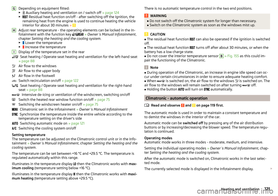
Depending on equipment fitted:
▶ Auxiliary heating and ventilation on / switch off » page 124
▶ Residual heat function on/off - after switching off the Ignition, the
remaining heat from the engine is used to continue heating the vehicle
interior for about 30 minutes »
Adjust rear temperature - the operating elements can be locked in the In-
fotainment with the function key
» Owner´s Manual Infotainment ,
chapter Setting the heating and the cooling system .
▶ Lower the temperature
▶ Increase the temperature
Display of the temperature set in the rear Seat heating / Operate seat heating and ventilation for the left-hand seat
» page 88
Air flow to the windows
Air flow to the upper body
Air flow in the footwell
Switch recirculation on/off » page 122
Seat heating / Operate seat heating and ventilation for the right-hand
seat » page 88
Intensive de-icing or ventilation of the windscreen, switching on/off
Switch the heated rear window function on/off » page 75
Switching the windscreen heater on/off » page 75
Climatronic set in the Infotainment » Owner´s Manual Infotainment
Synchronize the temperature inside the entire vehicle according to the
temperature setting on the driver's side
Switching automatic mode on » page 121
Switching the cooling system on/off
Setting temperature
The temperature can be adjusted on the Climatronic control unit or in the Info-
tainment » Owner´s Manual Infotainment , chapter Setting the heating and the
cooling system .
The temperature can be set between +16 °C and +29.5 °C. The temperature is
regulated automatically within this range.
Illuminates in the temperature display then the Climatronic works with
max-
imum cooling (temperature setting below +16 °C).
Illuminates in the temperature display then the Climatronic works with
maxi-
mum heating (temperature setting above +29.5 °C).
GHIThere is no automatic temperature control in the two end positions.WARNING■
Do not switch off the Climatronic system for longer than necessary.■Switch on the Climatronic system as soon as the windows mist up.
CAUTION
■The residual heat function can also be operated if the ignition is switched
off.■
The residual heat function
turns off after about 30 minutes, or when the
battery has a low charge state.
■
Do not cover the interior temperature sensor
B
» Fig. 155 as this could im-
pair the functioning of the Climatronic.
Note
■ During operation of the Climatronic, an increase in engine idle speed can oc-
cur under certain circumstances in order to ensure adequate heating comfort.■
When
is switched on, the air flow to the windows
is switched on. The
air flow to the windows will remain switched on after turning
off.
■
Holding the button
will turn on
automatically.
Climatronic - automatic operation
Read and observe
and on page 119 first.
The automatic mode is used in order to maintain a constant temperature and
to demist the windows in the interior of the car.
Automatic mode can be switched off by pressing any of the air distribution
buttons or by increasing/decreasing the blower speed. The temperature regu-
lation is continued.
Operating modes
Automatic mode works in three modes - moderate, medium, and intensive.
Setting the individual operating modes » Owner´s Manual Infotainment , chap-
ter Setting the heating and the cooling system .
After the automatic mode is switched on, Climatronic works in the last selec-
ted mode.
The currently selected mode is displayed in the Infotainment display.
121Heating and ventilation
Page 150 of 276

Fig. 178
Sampled areas and range of the
sensors
Read and observe and on page 147 first.
The system uses ultrasound waves to calculate the distance between the
bumper and an obstacle. The ultrasonic sensors are, depending on vehicle
equipment, located in the back or in the front bumper » Fig. 177.
Depending on the equipment, the following system variants are possible
» Fig. 178 .
▶ Variant 1: warns of obstacles in the areas
C
,
D
.
▶ Variant 2: warns of obstacles in the areas
A
,
B
,
C
,
D
.
▶ Variant 3: warns of obstacles in the regions
A
,
B
,
C
,
D
,
E
.
Approximate range of sensors (in cm)
Area » Fig. 178Variant 1
(4 sensors)Version 2
(8 sensors)Variant 3
(12 sensors)A-120120B-6090C160160160D606090E--90
Audible signals
The interval between the acoustic signals becomes shorter as the clearance is
reduced. A continuous tone sounds from a distance of approx. 30 cm - danger
area. From this moment on do not continue driving!
The acoustic signals can be set in the Infotainment » Owner´s Manual Infotain-
ment , chapter CAR - Vehicle Settings .
Towing a trailer
When towing, or when another accessory is connected to the trailer socket on-
ly the areas
A
and
B
» Fig. 178 are active in the system.
Note■
If with Version 3 vehicles not all fields around the vehicle are active after ac-
tivation the vehicle should be moved forwards or backwards.■
The signal tones for front obstacle recognition are factory-set to be higher
than for rear obstacle recognition.
Display in the Infotainment display
Fig. 179
Display
Read and observe and on page 147 first.
Function buttons and obstacle warning » Fig. 179ARoad display. Depending on the Infotainment type: Switching off park assistant dis-
play. Switching audible parking signals on/off.Change to rear-view camera display .Message: Look! Safe to move?Colour of an object detected in the collision area (the distance to the
obstacle is less than 30 cm).
Do not continue driving in the direc-
tion of the obstacle!Colour of an object detected in the manoeuvring area (the distance to
the obstacle is more than 30 cm).Colour of an object detected in the outside the manoeuvring area (the
distance to the obstacle is more than 30 cm).System failure (there is no indication of obstacles).
Road display
The roadway display varies depending on the steering angle
A
» Fig. 179 and
displays the roadway on which the vehicle would take with the current steer-
ing wheel position.
148Driving
Page 155 of 276
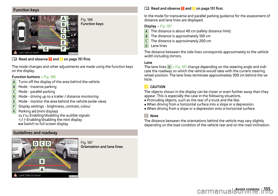
Function keysFig. 186
Function keys
Read and observe and on page 151 first.
The mode changes and other adjustments are made using the function keys
on the display.
Function buttons » Fig. 186
Turns off the display of the area behind the vehicle
Mode - traverse parking
Mode - parallel parking
Mode - driving up to a trailer / distance monitoring
Mode - monitor the area behind the vehicle (wide view)
Display settings - brightness, contrast, colour
Parking aid (mini display)
Enabling/disabling the audible signals
Enabling/disabling the mini display
Switch to full screen display
Guidelines and roadway
Fig. 187
Orientation and lane lines
ABCDEFGRead and observe and on page 151 first.
In the mode for transverse and parallel parking guidance for the assessment of
distance and lane lines are displayed.
Display » Fig. 187
The distance is about 40 cm (safety distance limit)
The distance is approximately 100 cm
The distance is approximately 200 cm
Lane lines
The distance between the side lines corresponds approximately to the vehicle width including mirrors.
Lane
The lane lines
D
» Fig. 187 change depending on the steering angle and indi-
cate the roadway on which the vehicle would take with the current steering
wheel position. The lane lines terminate approximately 300 cm behind the ve-
hicle.
CAUTION
The objects shown in the display can be closer or even further away than they
appear. This is especially the case in the following situations.■
Protruding objects, such as the rear of a truck and the like.
■
When driving from a horizontal surface into a slope or a depression.
■
When driving from a slope or a depression onto a horizontal surface.
Note
The distance between the orientations behind the vehicle may vary slightly
depending on the load condition of the vehicle rear and on the road inclination.ABCD153Assist systems
Page 172 of 276
With automatic braking the symbol appears » Fig. 208 in the display.
Advance warning
If the system detects a risk of collision, the symbol
» Fig. 208 appears in the
display and you will hear an acoustic signal.
At the same time, the braking system is prepared for possible emergency brak- ing.
The pre-warning display can occur in the following situations.
▶ If there is a risk of collision with a moving obstacle in a driving speed range of
about 30 km/h to about 210 km/h.
▶ There is a risk of a collision with a stationary moving obstacle in a vehicle
speed range of approximately 30 km/h to about 85 km/h.
With a warning the brake pedal must be pressed or the moving obstacle is to
be avoided!
Acute alert
If the driver does not react to the advance warning, the system briefly applies
the brake automatically via an active brake intervention to draw attention to
the potential danger of a collision again.
Automatic Braking
If the driver fails to respond to the acute warning, the system starts to apply
the brakes automatically with increasing stopping power in several stages.
Brake assist
If the driver brakes inadequate with an impending collision, the system auto-
matically increases braking force.
The braking assistance only occurs as long as the brake pedal is being firmly
pressed down.
Note
■ If an automatic brake intervention is triggered by the system, the pressure in
the brake system increases and the brake pedal cannot be operated with the
normal pedal stroke.■
The automatic braking interventions can be cancelled by pressing the accel-
erator pedal or by steering intervention.
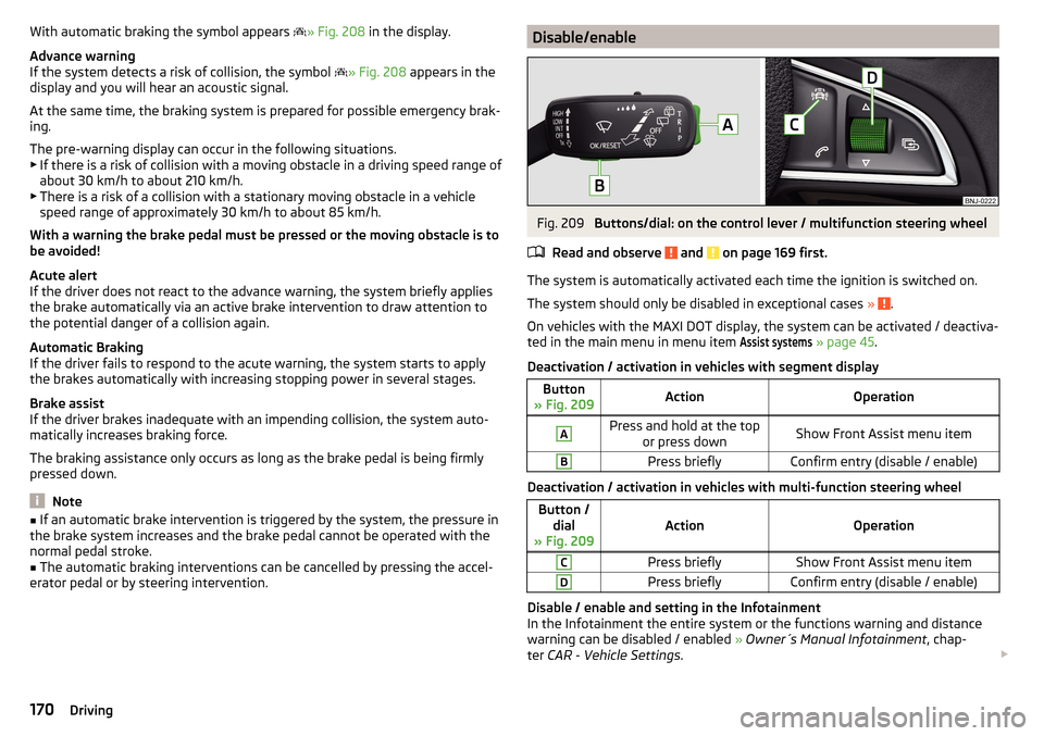
Disable/enableFig. 209
Buttons/dial: on the control lever / multifunction steering wheel
Read and observe
and on page 169 first.
The system is automatically activated each time the ignition is switched on. The system should only be disabled in exceptional cases »
.
On vehicles with the MAXI DOT display, the system can be activated / deactiva-
ted in the main menu in menu item
Assist systems
» page 45 .
Deactivation / activation in vehicles with segment display
Button
» Fig. 209ActionOperationAPress and hold at the top or press downShow Front Assist menu itemBPress brieflyConfirm entry (disable / enable)
Deactivation / activation in vehicles with multi-function steering wheel
Button /dial
» Fig. 209ActionOperation
CPress brieflyShow Front Assist menu itemDPress brieflyConfirm entry (disable / enable)
Disable / enable and setting in the Infotainment
In the Infotainment the entire system or the functions warning and distance warning can be disabled / enabled » Owner´s Manual Infotainment , chap-
ter CAR - Vehicle Settings .
170Driving
Page 175 of 276
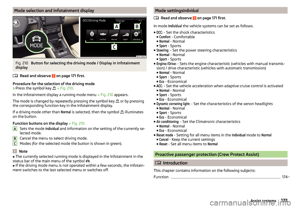
Mode selection and Infotainment displayFig. 210
Button for selecting the driving mode / Display in Infotainment
display
Read and observe
on page 171 first.
Procedure for the selection of the driving mode
›
Press the symbol key
» Fig. 210 .
In the Infotainment display a running mode menu » Fig. 210 appears.
The mode is changed by repeatedly pressing the symbol key or by pressing
the corresponding function key in the Infotainment display.
If a driving mode other than
Normal
is selected, then the symbol illuminates
on the button.
Function buttons on the display » Fig. 210
Sets the mode
Individual
and information on the setting of the currently se-
lected mode.
Cancel the menu to select driving mode.
Modes (for the selected mode the button is shown in green).
Note
■ The currently selected running mode is displayed in the Infotainment in the
status bar of the main menu of the symbol .■
If the driving mode menu is not operated within a few seconds, the Infotain-
ment switches to the last selected menu or switches off.
ABCMode settingsIndividual
Read and observe on page 171 first.
In mode
Individual
the vehicle systems can be set as follows.
■
DCC:
- Set the shock characteristics
■
Comfort
- Comfortable
■
Normal
- Normal
■
Sport
- Sports
■
Steering:
- Set the power steering characteristics
■
Normal
- Normal
■
Sport
- Sports
■
Engine:
/
Drive:
- Sets the engine characteristic (vehicles with manual transmis-
sion) / drive characteristic (vehicles with automatic transmission)
■
Normal
- Normal
■
Sport
- Sports
■
Eco
- Economical
■
ACC:
- Set the vehicle acceleration when adaptive cruise control is activated
■
Normal
- Normal
■
Sport
- Sports
■
Eco
- Economical
■
Dynamic cornering light:
- Set the characteristics of the xenon headlights
■
Normal
- Normal
■
Sport
- Sports
■
Eco
- Economical
■
Air conditioning:
- Set the Climatronic characteristics
■
Normal
- Normal
■
Eco
- Economical
■
Reset mode
- Setting for all menu items in the
Individual
mode to
Normal
■
Cancel
- Keep the current settings
■
Reset
- Set all menu items to
Normal
Proactive passenger protection (Crew Protect Assist)
Introduction
This chapter contains information on the following subjects:
Function
174
173Assist systems
Page 237 of 276
Synchronising the remote controlRead and observe
on page 234 first.
If the vehicle does not unlock when pressing the remote control, the key may
not be synchronised. This can occur when the buttons on the remote control
key are actuated a number of times outside of the operative range of the
equipment or the battery in the remote control key has been replaced.
Synchronise the key as follows.
›
Press any button on the remote control key.
›
Unlock the door with the key in the lock cylinder within 1 minute of pressing the button.
replace battery in the remote control the auxiliary heating
(auxiliary heating)
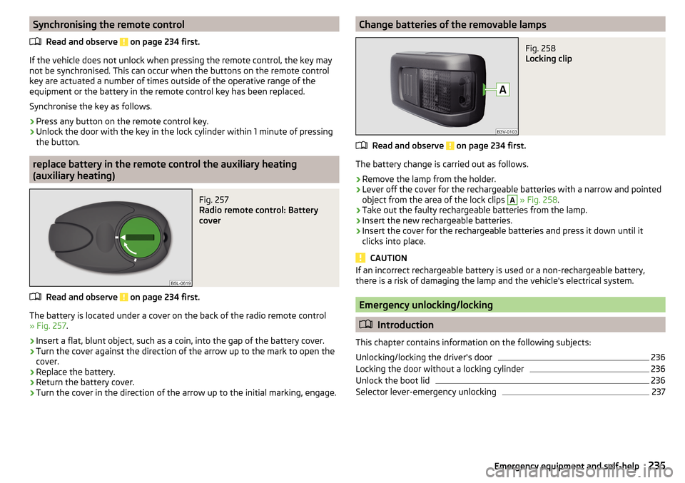
Fig. 257
Radio remote control: Battery
cover
Read and observe on page 234 first.
The battery is located under a cover on the back of the radio remote control
» Fig. 257 .
›
Insert a flat, blunt object, such as a coin, into the gap of the battery cover.
›
Turn the cover against the direction of the arrow up to the mark to open the
cover.
›
Replace the battery.
›
Return the battery cover.
›
Turn the cover in the direction of the arrow up to the initial marking, engage.
Change batteries of the removable lampsFig. 258
Locking clip
Read and observe on page 234 first.
The battery change is carried out as follows.
›
Remove the lamp from the holder.
›
Lever off the cover for the rechargeable batteries with a narrow and pointed
object from the area of the lock clips
A
» Fig. 258 .
›
Take out the faulty rechargeable batteries from the lamp.
›
Insert the new rechargeable batteries.
›
Insert the cover for the rechargeable batteries and press it down until it
clicks into place.
CAUTION
If an incorrect rechargeable battery is used or a non-rechargeable battery,
there is a risk of damaging the lamp and the vehicle's electrical system.
Emergency unlocking/locking
Introduction
This chapter contains information on the following subjects:
Unlocking/locking the driver's door
236
Locking the door without a locking cylinder
236
Unlock the boot lid
236
Selector lever-emergency unlocking
237235Emergency equipment and self-help
Page 238 of 276

Unlocking/locking the driver's doorFig. 259
Driver's door handle: masked lock cylinder / key rotations for un-
locking and locking
Fig. 260
Handle on the driver's door: Key / KESSY
The driver's door can be unlocked or locked in an emergency.
›
Pull on the door handle and hold in place.
›
Insert the vehicle key into the slot on the bottom of the cover » Fig. 259.
›
Open the cover in the direction of the arrow.
›
Release the door handle.
›
For vehicles with LHD insert the remote control key with the buttons facing
up into the lock cylinder and unlock or lock the vehicle.
›
For vehicles with RHD insert the remote control key directed with buttons
down into the lock cylinder and unlock or lock the vehicle.
On vehicles with the KESSY key point the emergency key with the handle
down into the key cylinder » Fig. 260.
›
Pull on the door handle and hold in place.
›Replace the cap in its original position.
CAUTION
Make sure you do not damage the paint when performing an emergency lock-
ing/unlocking.
Locking the door without a locking cylinder
Fig. 261
Emergency locking: Left/right rear door
An emergency locking mechanism, which is only visible after opening the door,
is located on the face side of the doors which have no locking cylinder.
›
Remove the cover
A
» Fig. 261 .
›
Insert the vehicle key into the slot and turn in the direction of the arrow
(sprung position).
›
Replace the cover
A
.
Unlock the boot lid
Fig. 262
Unlock boot lid: variant 1 / variant 2
The boot lid can be unlocked manually.
236Do-it-yourself
Page 261 of 276
Fuel supply30
Gear changes42
Service interval49
Disposal Acceptance and recycling of used vehicles
193
Distance driven31
Distance warning Warning light
40
Door Child safety lock
57
Closing56
Emergency locking236
Emergency locking the driver's door236
Opening56
Door warning41
Drive Driving through water
141
DriveGreen140
Driver Steering Recommendation (DSR)145
Driving Emissions
248
Fuel consumption248
through water141
driving data operation
43
Driving mode171
driving mode select Normal mode
172
Driving Mode Selection171
DSR145
Dynamic Light Assist72
E
ECO-TIP
49
Eco-tips49
Economical driving Tips
139
Economy mode Warning light
41
EDL145
Electrical boot lid set the top position of the lid
60
Electrical power windows Buttons in the driver's door
62
Electric boot lid Force limit
59
Manual operation59
Electric luggage compartment lid Malfunctions
61
Operating60
Electric parking brake133
Electric window lifter61, 63
Button in the passenger door63
Button in the rear doors63
Window operation malfunctions64
Electronic differential lock (EDL, XDS)145
Electronic immobilizer126
emergency replace battery in the remote control
235
Emergency Changing a wheel
224
Hazard warning light system71
Jump-starting230
Locking the door without a locking cylinder236
Locking the driver's door236
Selector lever-unlocking237
Switch off the engine by pressing a button129
Towing the using the tow hitch233
Towing the vehicle231
Tyre repair228
Unlocking the driver's door236
emergency equipment reflective vest
223
Emergency equipment Fire extinguisher
223
First aid kit222
Jack223
Vehicle tool kit223
Warning triangle222
Emissions248
Engine Information messages
38
Running-in139
Engine compartment206
Brake fluid212
Overview208
Vehicle battery213
Engine number246
engine oil specification
209
Engine oil209
Checking210
Replenishing210
Warning light38
EPC Warning light
35
ESC Operation
144
Warning light34
ESC Sport144
Exhaust emissions control system Warning light
34
F
Fastening elements
106
Fatigue detection182
Function182
Information messages182
Films195
Fire extinguisher223
First aid kit222
Floor covering Fixing
108
in the luggage compartment108
Fog lights Warning light
36
Fog Lights70
Fold in passenger's mirror80
259Index
Page 269 of 276

Materials199
Natural leather199
Plastic parts196
Polishing vehicle paint work195
Rubber seals196
Safety belt200
Seat covers200
Under-body protections198
washing193
Vehicle condition see Auto-check control
41
Vehicle data sticker246
Vehicle data sticker and nameplate Vehicle data sticker and nameplate
246
Vehicle dimensions249, 250
Vehicle height249, 250
Vehicle Identification Number (VIN)246
Vehicle length249, 250
Vehicle tool kit223
Vehicle width249, 250
Ventilation Front seats
89
Seats88
vest holder for reflective vest
223
VIN Vehicle Identification Number
246
Virtual pedal61
Visibility75
Visors see front sun visors
76
see Sun screen76
W
Warning lights
31
Warning symbols see Warning lights
31
Warning triangle222
warning when speeding44
Washing Automatic car wash system194
by hand193
High-pressure cleaner194
Washing vehicles193
Waste container93
Water in the fuel filter Warning light
40
Warning messages40
Weather conditions190
Wheel bolts Anti-theft wheel bolts
225
Caps225
Loosening and tightening226
Wheel rims217
Wheels Age of wheels
217
Changing224
Driving style218
Full trim225
General information217
Load index220
Snow chains221
Speed symbol220
Storage of wheels217
Tyre damage219
Tyre pressure217
Tyre size220
Tyre wear218
Tyre wear indicator219
unidirectional tyres219
Wheel balance218
Wheel replacement219
Winter tyres221
Wi-Fi Connection
50
Password50
Password change51
Setting51
Wi-Fi Direct Connection51
Password change51
Setting51
Window operation61
Button in the passenger door63
Button in the rear doors63
Buttons in the driver's door62
Comfort operation63
Malfunctions64
Window wiper Replacing the rear window wiper blade
238
Windscreen Heater
75
Windscreen washer fluid Checking
208
Replenishing208
Warning light40
Winter208
Windscreen washers Windscreen washers
78
Windscreen washer system208
Windscreen wipers automatic rear window wipers
78
operation78
Replacing the windscreen wipers237
Windscreen washer fluid208
Windscreen wipers and washers77
Winter operation220
De-icing windows196
Snow chains221
Winter tyres221
Winter tyres See Wheels
221
Wiper blades198
Service position of the windscreen wiper arms 237
Wiper interval
78
Wipers Maintaining wiper blades
198
267Index