turn signal SKODA SUPERB 2015 3.G / (B8/3V) Owner's Guide
[x] Cancel search | Manufacturer: SKODA, Model Year: 2015, Model line: SUPERB, Model: SKODA SUPERB 2015 3.G / (B8/3V)Pages: 276, PDF Size: 42.14 MB
Page 155 of 276
Function keysFig. 186
Function keys
Read and observe and on page 151 first.
The mode changes and other adjustments are made using the function keys
on the display.
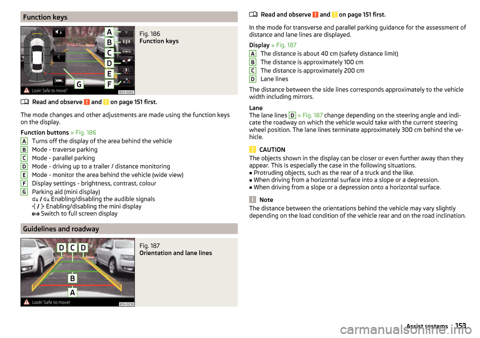
Function buttons » Fig. 186
Turns off the display of the area behind the vehicle
Mode - traverse parking
Mode - parallel parking
Mode - driving up to a trailer / distance monitoring
Mode - monitor the area behind the vehicle (wide view)
Display settings - brightness, contrast, colour
Parking aid (mini display)
Enabling/disabling the audible signals
Enabling/disabling the mini display
Switch to full screen display
Guidelines and roadway
Fig. 187
Orientation and lane lines
ABCDEFGRead and observe and on page 151 first.
In the mode for transverse and parallel parking guidance for the assessment of
distance and lane lines are displayed.
Display » Fig. 187
The distance is about 40 cm (safety distance limit)
The distance is approximately 100 cm
The distance is approximately 200 cm
Lane lines
The distance between the side lines corresponds approximately to the vehicle width including mirrors.
Lane
The lane lines
D
» Fig. 187 change depending on the steering angle and indi-
cate the roadway on which the vehicle would take with the current steering
wheel position. The lane lines terminate approximately 300 cm behind the ve-
hicle.
CAUTION
The objects shown in the display can be closer or even further away than they
appear. This is especially the case in the following situations.■
Protruding objects, such as the rear of a truck and the like.
■
When driving from a horizontal surface into a slope or a depression.
■
When driving from a slope or a depression onto a horizontal surface.
Note
The distance between the orientations behind the vehicle may vary slightly
depending on the load condition of the vehicle rear and on the road inclination.ABCD153Assist systems
Page 159 of 276
When the system is activated, the symbol illuminates.
Parking space search
Read and observe
and on page 156 first.
The system is able to find a parking space in a number of parallel and trans-
verse parked vehicles on the passenger's or driver's side.
Process with the parking space search
›
Slowly drive past a row of parked vehicles.
›
Activate the system with the symbol key » Fig. 191
on page 156 .
The system will automatically search for a parking space on the passenger
side.
If the system finds a parking space, then the recommended parking mode is
made and this parking space is included in the display » Fig. 193 on page 157
or » Fig. 194 on page 158 -
.
Activate the turn signal on the driver's side if you wish to look fro a parking
space on this side of the road. The display changes and the system searches
for a parking space on the driver's side.
Note
If the symbol (km / h) is shown in the display while you are looking for a
parking space, the vehicle speed should be reduced below 40 km / hr (parallel parking) or below 20 km / hr (Transverse parking).
Switch to park mode
Fig. 192
Menus with the parking modes: Display
Read and observe and on page 156 first.
While the parking space search is going on and before the start of the parking,
a menu may appear showing other suitable parking modes.
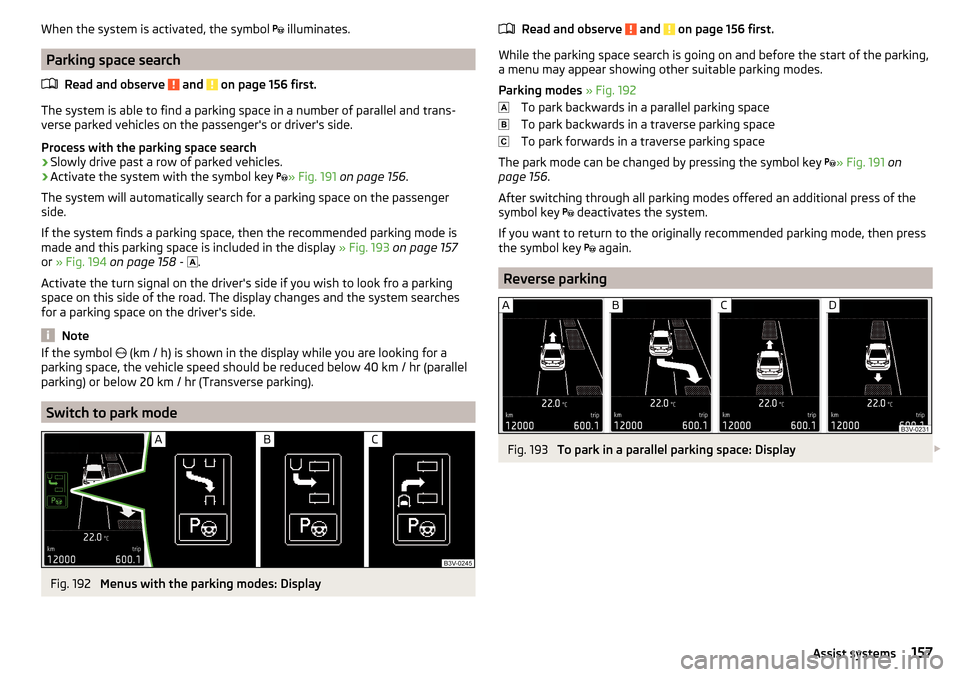
Parking modes » Fig. 192
To park backwards in a parallel parking space
To park backwards in a traverse parking space
To park forwards in a traverse parking space
The park mode can be changed by pressing the symbol key » Fig. 191
on
page 156 .
After switching through all parking modes offered an additional press of the
symbol key deactivates the system.
If you want to return to the originally recommended parking mode, then press
the symbol key again.
Reverse parking
Fig. 193
To park in a parallel parking space: Display
157Assist systems
Page 161 of 276

As soon as the parking procedure is completed, an audible signal sounds and
the following message appears in the display: Park Assist stopped. Take over steer-ing!
Parking space found by the driver
The system activation is also possible if the vehicle has already been partially
moved to a suitable parking space.
›
Press the symbol key
» Fig. 191 on page 156 . The display shows the follow-
ing » Fig. 195 .
The further procedure is analogous to that for reverse parking.
›
Follow the system instructions shown in the display.
As soon as the parking procedure is completed, an audible signal sounds and
the following message appears in the display:
Park Assist stopped. Take over steer-ing!
Departing from a parallel parking space
Read and observe
and on page 156 first.
The system supports the driver when leaving a parking space of a parallel
parking space.
Leaving a parking space process
›
Press the symbol key
» Fig. 191 on page 156 .
The following message is displayed:
Park Assist: indicate and engage reverse›
Activate the turn signal for side of the vehicle where the parking space is out
of which you wish to manoeuvre.
›
Select reverse gear or move the selector lever into position R.
The further procedure is analogous to that for reverse parking.
›
Follow the system instructions shown in the display.
As soon as the parking procedure is completed, an audible signal sounds and
the following message appears in the information display:
Please take over steer-ing and drive on.Automatic brake assist
Read and observe
and on page 156 first.
Automatic brake assist when speeding
If a velocity of 7 km / h is exceeded during the parking manoeuvre for the first
time, the speed will be automatically reduced by the system to less than 7 km /
h. This prevents the parking manoeuvre from aborting.
Automatic emergency braking
If the system detects a risk of collision during parking, automatic emergency
braking takes place to prevent a collision.
The parking is terminated by the emergency braking.
CAUTION
The automatic emergency braking is not triggered by the system when the
parking process stops due to the speed of 7 km / hr being exceeded!
Information messages
Read and observe
and on page 156 first.
The warning symbols are shown in the instrument cluster display.
Park Assist stopped. Speed too high.
If a speed of 50 km / h is exceeded while searching for a parking space, the
system with the key symbol is must be reactivated.
Speed too high. Take over steering!
The parking is terminated if the speed exceeds 7 km / hr.
Park Assist stopped. Driver steering intervention
The parking procedure is terminated due to a driver steering intervention.
Park Assist finished. ASR deactivated.
The parking procedure cannot be carried out because the TCS system is deac-
tivated » page 143 , Braking and stabilisation systems . Activate the TCS.
ASR deactivated. Take over steering!
The parking procedure was ended because TCS was deactivated during the
parking procedure.
Trailer: Park Assist stopped.
159Assist systems
Page 178 of 276

The system can intervene when the following basic conditions are present.The system is activated.
The vehicle is travelling at more than about 65 km/h 1)
.
The boundary lines are clearly visible (appropriate longitudinal markings).
The boundary line of at least one side of the lane is detected.
The driver's hands are on the steering wheel.
The lane is more than 2.5 m in width.
If the turn signal is switched on prior to driving over the boundary line (e.g.
when making a turn), no steering intervention takes place when the vehicle
approaches the boundary line. The system regards the situation as an inten-
ded lane change.
Warning lights in the instrument clusterWarning lightMeaningThe system is active, but not ready to intervene.The system is active and ready to intervene or is currently
intervening.
Adaptive lane assist
Adaptive lane assist helps to keep the vehicle in the position between the
boundary lines selected by the driver, by means of steering intervention.
If the system detects only one boundary line, it will help to maintain the selec-
ted proximity from said boundary line.
If the proximity to the detected boundary line is changed, the system quickly
adapts and maintains the newly-selected position.
WARNINGThe system function may be restricted if, for example there is danger due
to ruts on a downhill road or in a crosswind.Activation / deactivation
Read and observe
and on page 175 first.
The activation or deactivation of the system can be carried out in one of twoways. ▶ In the instrument cluster display » page 48, Menu item
Assist systems
.
▶ Infotainment » Owner´s Manual Infotainment , chapter CAR - vehicle set-
tings .
Adaptive tracking can also be enabled or disabled In Infotainment.
After switching off and switching on the ignition, the system setting is re-
tained.
Information messages
Read and observe
and on page 175 first.
The warning symbols are shown in the instrument cluster display.
Lane Assist not available. No sensor view.
The windscreen is dirty, iced over or misted up in the camera viewing range.
Clean the windscreen or remove the obstacles.
Lane Assist currently not available.
The system has limited functionality due to a temporary error. Try to re-acti-
vate the machine.
Error: Lane Assist
System error detected. Seek help from a specialist garage.
Lane Assist: take over steering!
The system has detected that there are no hands on the steering wheel. In
this case the Assist system is not ready to intervene. Place your hands on the
steering wheel.
1)
Not valid for vehicles with the traffic jam assistant » page 179.
176Driving
Page 234 of 276
Vehicles with automatic transmission may be towed in with a tow bar or a tow
rope or with the front wheels raised. If the vehicle is raised at rear, the auto-
matic gearbox is damaged! If possible, the vehicle should be towed with the
engine running or at least with the ignition on.
Driver of the tow vehicle›
Engage the clutch gently when starting off or depress the accelerator partic-
ularly gently if the vehicle is fitted with an automatic gearbox.
›
Only then approach correctly when the rope is taut.
The maximum towing speed is 50 km/h.
Driver of the towed vehicle
›
Switch on the ignition so that the steering wheel is not locked and so that
the turn-signal lights, windscreen wipers and windscreen washer system can
be used.
›
Take the vehicle out of gear or move the selector lever into position N if the
vehicle is fitted with an automatic gearbox.
Please note that the brake servo unit and power steering only operate if the
engine is running. If the engine is not running, significantly more physical force
is required to depress the brake pedal and steer the vehicle.
If using a tow rope, ensure that it is always kept taught.
General information for the towing process
Both drivers should be familiar with the problems which might occur while a vehicle is being towed. Unskilled drivers should not attempt to tow in another
vehicle or to be towed in.
The vehicle must be transported on a special breakdown vehicle or trailer if it
is not possible to tow in the vehicle in the way described or if the towing dis-
tance is greater than 50 km.
If the gearbox has no oil, your vehicle must be towed with the front axle raised
clear of the ground or on a breakdown vehicle or trailer.
To protect both vehicles when tow-starting or towing, the tow rope should be elastic. Thus one should only use plastic fibre rope or a rope made out of a
similarly elastic material.
Attach the tow rope or the tow bar to the towing eyes » page 232 or
» page 233 to the detachable ball head of the towing device » page 184 .
WARNING■
When towing, exercise increased caution.■Do not use spiral rope for towing » Fig. 251- , the towing eye may un-
screw from the vehicle - risk of accident.■
Ensure tow rope is not twisted - risk of accident.
CAUTION
■ Do not start engine by towing - there is a risk of damaging the engine parts.
The battery from another vehicle can be used as a jump-start aid » page 230,
Jump-starting .■
There is always a risk of excessive stresses and damage resulting at the
points to which you attach the tow rope or tow bar when you attempt to tow a
vehicle which is not standing on a paved road.
Note
We recommend using a tow rope from ŠKODA Original Accessories, which is
available from a ŠKODA Partner.
Front towing eye
Fig. 252
Removing the cap / fitting the towing eye
Read and observe
and on page 232 first.
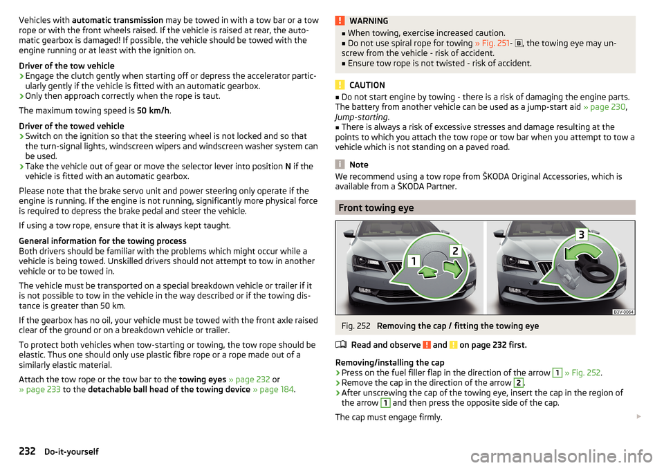
Removing/installing the cap
›
Press on the fuel filler flap in the direction of the arrow
1
» Fig. 252 .
›
Remove the cap in the direction of the arrow
2
.
›
After unscrewing the cap of the towing eye, insert the cap in the region of
the arrow
1
and then press the opposite side of the cap.
The cap must engage firmly.
232Do-it-yourself
Page 244 of 276
No.Consumer18Databus, battery data module19Windscreen wipers20Alarm21Not assigned22Engine control unit23Starter24Electrical auxiliary heating system31Not assigned32Not assigned33SCR34Not assigned35Not assigned36Not assigned37Auxiliary heating38Not assigned
Bulbs
Introduction
This chapter contains information on the following subjects:
Bulb arrangement in the headlights
243
Replace the bulb for the dipped and main beam (Halogen-headlamp)
243
Change bulb for turn signal switch (halogen headlight)
243
Replacing the bulb for the fog light
244
Rear Light
244
Replacing bulbs in rear light
245
Some manual skills are required to change a bulb. For this reason, we recom-
mend having bulbs replaced by a specialist garage or seeking other expert help
in the event of any uncertainties.
▶ Switch off the ignition and the relevant lights before replacing a bulb.
▶ Faulty bulbs must only be replaced with the same type of bulbs. The designa-
tion is located on the light socket or the glass bulb.
A stowage compartment for replacement bulbs is located in a plastic box in
the spare wheel or underneath the floor covering in the luggage compartment.
We recommend having the headlight settings checked by a specialist garage
after replacing a bulb in the low, high or fog beam.
In case of failure of a xenon gas discharge lamp or an LED diode, visit a special- ist garage.WARNING■ Always read and observe the warnings before completing any work in the
engine compartment » page 206.■
Accidents can be caused if the road in front of the vehicle is not suffi-
ciently illuminated and the vehicle cannot or can only be seen with difficul-
ty by other road users.
■
H7 and H8 bulbs are pressurised and may burst when changing the bulb -
risk of injury! We therefore recommended wearing gloves and safety
glasses when changing a bulb.
■
Do not carry out any work on the xenon gas discharge lamps - risk of
death!
CAUTION
■ Do not take hold of the glass bulb with naked fingers (even the smallest
amount of dirt reduces the working life of the light bulb). Use a clean cloth,
napkin, or similar.■
The protective cap of the bulb must always be properly inserted into the
headlamp. Water and dirt may get into the headlamp if the cover is not re-
placed properly - there is a risk of damage to the headlamp!
Note
■ This Owner's Manual only describes the replacement of bulbs where it is pos-
sible to replace the bulbs on your own without any complications arising. Other
bulbs must be replaced by a specialist garage.■
We recommend that a box of replacement bulbs always be carried in the ve-
hicle. Replacement bulbs can be purchased from ŠKODAOriginal Accessories.
242Do-it-yourself
Page 245 of 276
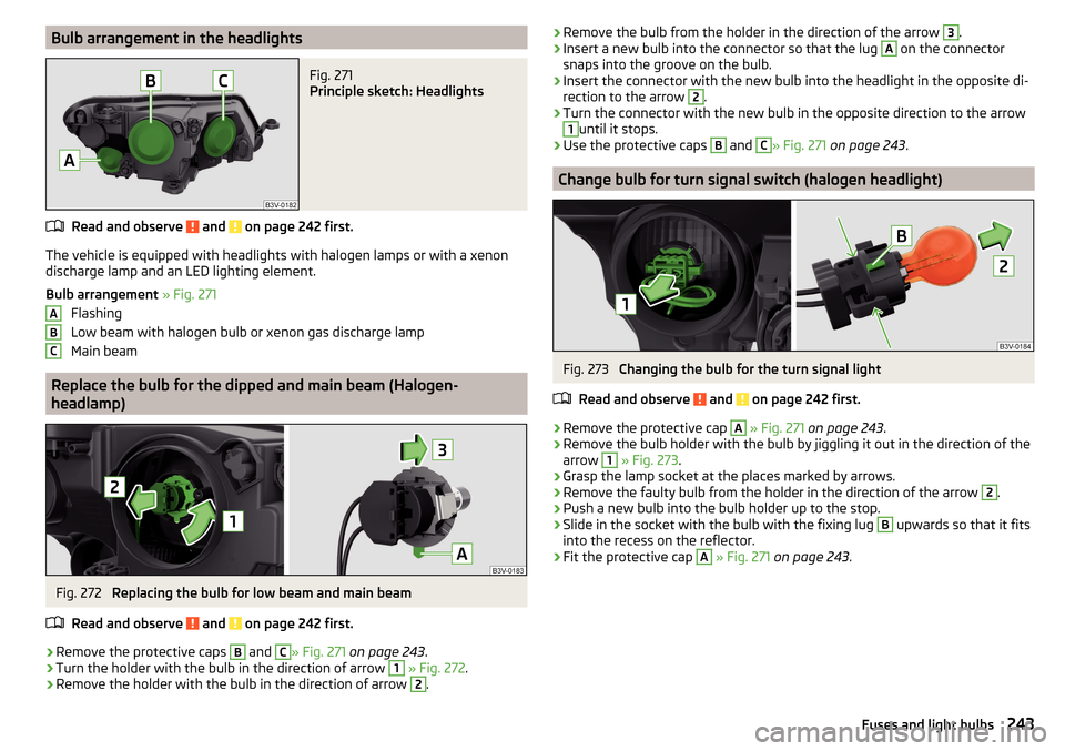
Bulb arrangement in the headlightsFig. 271
Principle sketch: Headlights
Read and observe and on page 242 first.
The vehicle is equipped with headlights with halogen lamps or with a xenon
discharge lamp and an LED lighting element.
Bulb arrangement » Fig. 271
Flashing
Low beam with halogen bulb or xenon gas discharge lamp
Main beam
Replace the bulb for the dipped and main beam (Halogen- headlamp)
Fig. 272
Replacing the bulb for low beam and main beam
Read and observe
and on page 242 first.
›
Remove the protective caps
B
and
C
» Fig. 271 on page 243 .
›
Turn the holder with the bulb in the direction of arrow
1
» Fig. 272 .
›
Remove the holder with the bulb in the direction of arrow
2
.
ABC›Remove the bulb from the holder in the direction of the arrow 3.›Insert a new bulb into the connector so that the lug A on the connector
snaps into the groove on the bulb.›
Insert the connector with the new bulb into the headlight in the opposite di-
rection to the arrow
2
.
›
Turn the connector with the new bulb in the opposite direction to the arrow
1
until it stops.
›
Use the protective caps
B
and
C
» Fig. 271 on page 243 .
Change bulb for turn signal switch (halogen headlight)
Fig. 273
Changing the bulb for the turn signal light
Read and observe
and on page 242 first.
›
Remove the protective cap
A
» Fig. 271 on page 243 .
›
Remove the bulb holder with the bulb by jiggling it out in the direction of the
arrow
1
» Fig. 273 .
›
Grasp the lamp socket at the places marked by arrows.
›
Remove the faulty bulb from the holder in the direction of the arrow
2
.
›
Push a new bulb into the bulb holder up to the stop.
›
Slide in the socket with the bulb with the fixing lug
B
upwards so that it fits
into the recess on the reflector.
›
Fit the protective cap
A
» Fig. 271 on page 243 .
243Fuses and light bulbs
Page 260 of 276

TOP TETHER25
Use of child safety seats i-Size25
Use of ISOFIX child seats24
Chrome parts Refer to vehicle maintenance
196
Cigarette lighter102
Clean Anodized parts
196
Chrome parts196
Cleaning Alcantara
199
and maintaining belts200
artificial leather199
headlight glasses197
materials199
natural leather199
plastic parts196
seats covers of the electrically heated seats200
wheels197
Cleaning safety belt
200
Cleaning seat covers
200
Cleaning the interior artificial leather
199
Seat covers200
Cleaning the vehicle exterior Camera lens
197
Cavity protection197
Decorative films195
Door locking cylinder197
Headlight glasses197
Protective films195
Under-body protection198
wheels197
Windows and external mirrors196
Cleaning vehicle193
Cleaning vehicle exterior194
Anodized parts196
Chrome parts196
Plastic parts196
Rubber seals196
Vehicle paint work195
Wiper blades198
Clean interior Safety belt
200
Climatronic air distribution control
122
Automatic operation121
Operating elements120
Clothes hook96
Cockpit 12 volt power outlet
100
Ashtray103
Cigarette lighter102
General view27
Lighting74
storage compartments90
useful equipment90
Comfort operation Window
63
COMING HOME71
compartments90
Component protection192
Components of the puncture repair kits228
Computer see multifunction display
42
Convenience operation sliding / tilting roof
65
convenience turn signal68
Coolant210
Checking211
Information messages38
Replenishing212
Temperature gauge30
Warning light38
CORNER see Headlights with CORNER function
71
Correct routing of seat belt
12
Correct seated position8
Front passenger10
Rear seats10
Correct seat position Driver
9
Counter for distance driven31
Crew Protect Assist173
cruise control operation
160
operation description161
Cruise Control System160
Cup holders92
D
DAY LIGHT see Daylight running lights
68
Daylight running lights68
DCC171
Warning light41
De-icing windows
196
De-icing the windscreen and rear window75
Deactivating an airbag19
Decorative films195
Delayed locking of the boot lid see boot lid
59
Diesel refer to Fuel
203
Diesel fuel Operation in winter
203
Diesel particulate filter39
information messages39
Digital Clock31
Dipstick210
Disconnecting and reconnecting vehicle battery
215
Display29
Compass points48
Coolant temperature30
258Index
Page 263 of 276
Interior lightFront74
Interior lighting Ambient lighting
75
Interior monitor58
iPad holder behind the head restraint
104
Handling104
in the rear armrest105
ISOFIX23
J
Jack
223
- fit226
Maintenance197
Jump-starting230
K
KESSY Boot lid
61
Locking54
Unlocking54
Virtual pedal61
Key Start the engine
127
Stopping the engine127
Switch off the ignition127
Switch on the ignition127
Key CAR see Infotainment
4
key for KESSY Remove emergency key
54
Key for KESSY Replacing the battery
234
Knee airbag17
L
Lamp failure Warning light
39
LampsWarning light39
Lane Assist see Lane Departure Warning
174
Warning light36
Lane Departure Warning174
Activation / deactivation176
Information messages176
Operation175
Leather Natural leather care
199
LEAVING HOME71
Lever Main beam
68
Turn signal68
Levers Windscreen wipers
78
Light Cockpit
74
COMING HOME / LEAVING HOME71
Fog Lights70
Headlamp Assistant72
Headlights with CORNER function71
Rear fog light70
Replacing bulbs242
travel mode70
Xenon headlight69
Light Assist72
lighting entry space
75
Lighting Luggage compartment
105
Lights67
Automatic driving lamp control69
Daylight running68
Hazard warning light system71
Headlight flasher68
Headlight range adjustment67
Low beam67
Main beam68
Parking lights67, 72
Switching on and off67
Turn signal68
Warning lights31
Load248
Locking Individual settings
56
KESSY54
Remote control53
Locking and unlocking the vehicle from the in- side
55
Locking the door without a locking cylinder Emergency
236
Long cargo channel86
Low beam67
Low temperature warning light Warning light
40
Low tyre pressure warning refer to the tyre pressure monitoring
183
Luggage compartment105
Cover108
Fastening elements106
Fix floor covering108
Fixing nets107
floor covering on both sides108
foldable hook107
Lighting105
Luggage net108
Net partition116
removable light114
Roll-up cover109
Side pockets112
Storage compartments under the floor cover- ing
113
tray with cargo element112
unlock manually236
Unlock the boot lid236
Variable loading floor115
261Index
Page 268 of 276

Towing deviceAccessories185
Towing eye front
232
Rear233
Towing protection58
Towing the vehicle231
Traction control (TCS)144
Traffic jam assistant179
Operating conditions179
Operation179
Traffic sign recognition180
Function181
Information messages182
Traffic Sign Recognition Additional display
181
Traffic signs see Traffic sign recognition
180
Trailer185
13-pin socket186
Coupling / uncoupling186
loading186
Safety eye186
Towing a trailer188
Trailer operation184
Trailer stabilization system (TSA)146
Trailer towing device Handling
184
Warning message184
Transmission Warning messages
37
Transport Luggage compartment
105
Roof rack117
Transporting90
Transporting children safely20
TSA146
Turn signal68
Turn signal system Warning light36
Tyre Damage
219
Explanation of the label220
see wheels220
Tyre load-bearing capacity see Wheels
220
Tyre pressure217
Warning light35
Tyre pressure monitoring183
Display35
Infotainment display183
Save tyre pressure values183
Tyre repair General notes
229
Preparations229
Pressure test230
Sealing and inflating the tyre229
Tyres217
new139
Tyre pressure217
Wear and tear218
Wear indicator219
Tyre size220
see wheels220
U
Umbrella Tray
97
Under-body Vehicle care
198
Under-body protection198
Unlocking Individual settings
56
KESSY54
Remote control53
Unlocking and locking52
USB99
Used vehicles Acceptance and recycling193
Useful equipment 230-volt socket
101
Ashtray103
Car park ticket holder91
Cigarette lighter102
Clothes hook96
Cup holders92
Glasses compartment95
Removable through-loading bag98
Storage compartment90
Using the selector lever136
V
Variable loading floor
115
Dividing the luggage compartment116
Folding up115
Position change115
Vehicle battery Automatic load deactivation
216
charging215
Checking the battery electrolyte level214
Cover214
Operation in winter214
Replacing215
Safety instructions213
Warning light37
Vehicle care Alcantara
199
Anodized parts196
Artificial leather199
Cavity protection197
Chrome parts196
Cleaning vehicle exterior194
Cleaning wheels197
Decorative and protective films195
Door locking cylinder197
Headlight glasses197
Interior care198
Maintenance195
266Index