gearbox SKODA SUPERB 2016 3.G / (B8/3V) User Guide
[x] Cancel search | Manufacturer: SKODA, Model Year: 2016, Model line: SUPERB, Model: SKODA SUPERB 2016 3.G / (B8/3V)Pages: 336, PDF Size: 53.89 MB
Page 209 of 336

WARNING (Continued)■If the vehicle stalls, with engine running, in the D, S , R or Tiptronic mode,
then the vehicle must be prevented from rolling away by means of the
brake pedal, parking brake or using the Auto Hold function. Even when the
engine is idling, the power transmission is never completely interrupted –
the vehicle creeps.■
When leaving the vehicle, the selector lever must always be set to P .
Otherwise, the vehicle could start to move - risk of accident.
CAUTION
■ If you want to move the selector lever from position N to position D / S whilst
driving, the engine must be running at idling speed.■
When stopping on a slope, never try to hold the vehicle using the accelerator
pedal – this may lead to gear damage.
Select selector lever position
Fig. 259
Selector lever settings / display
Read and observe and on page 206 first.
The selector lever can be moved through shifting to one of the following posi-
tions » Fig. 259 . In some positions you have to push the locking button
» page 207 , Selector lever lock .
When the ignition is switched on, the gearbox mode and the currently selected
gear are indicated in the display » Fig. 259.
Park - the position can be set only when the vehicle is at a standstill.
The drive wheels are mechanically locked.
Reverse gear - the position can be set only when the vehicle is at a stand-
still and the engine is at idling speed.
Neutral (idle position) - the power transmission to the drive wheels is in-
terrupted.
PRNForward mode / sports programme - the gear change takes place in the
position S at higher engine speeds than in mode D
(Sprung position) - choice between positions D and S
If the Sport driving mode is selected with the engine running » page 240, Se-
lect the driving mode (Driving Mode Selection) , the transmission is automati-
cally set in the S mode.
E – Economical driving mode
If the driving mode Eco or Individual (engine - Eco) » page 240 is selected and
the selection lever is in the setting D/S, the transmission is automatically set
to mode E. This mode cannot be selected with the selector lever.
The forwards mode is switched up or down automatically in mode E at lower
engine speeds than in mode D.
Selector lever lock
Fig. 260
Shift lock button
Read and observe and on page 206 first.
The selector lever is locked in mode P and N to prevent that the forward driv-
ing is selected accidentally, thereby setting the vehicle in motion.
The selector lever is locked only when the vehicle is stationary and at speeds
up to 5 km/h.
The selector lever lock is indicated by the illumination of the warning light.
Release the gear selector lever from P mode or N
›
Press the brake pedal and the lock button at the same time in the direction
of
1
» Fig. 260 .
To move the selector lever from mode N to D / S only the brake pedal is press-
ed.
D/S207Starting-off and Driving
Page 210 of 336
The selector lever is not locked when quickly moving across the position N
(e.g. from R to D/S ). This, for example, helps to rock out a vehicle that is stuck,
e.g. in a bank of snow. The selector lever lock will engage if the lever is in posi-
tion N for more than approx. 2 seconds without the brake pedal being de-
pressed.
If it is not possible to release the gear selector from mode P in the usual man-
ner, then this can be emergency unlocked » page 293.
Note
If you want to switch the selector lever from mode P to mode D/S or vice ver-
sa, move the selector lever quickly. This prevents that you accidentally select
mode R or N.
Manual shifting of gears (Tiptronic)
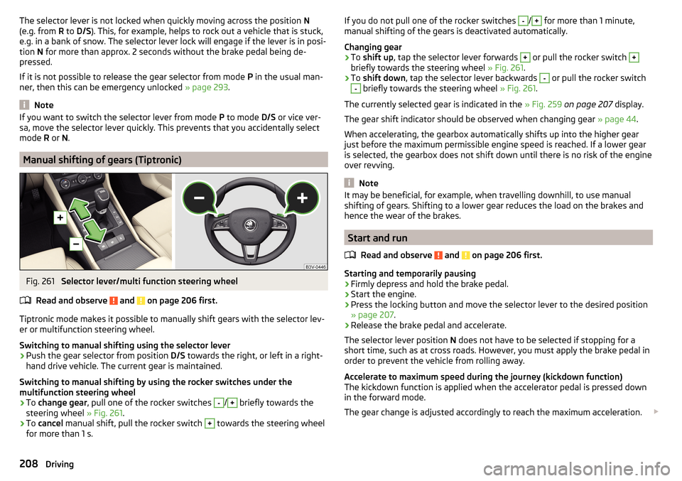
Fig. 261
Selector lever/multi function steering wheel
Read and observe
and on page 206 first.
Tiptronic mode makes it possible to manually shift gears with the selector lev-
er or multifunction steering wheel.
Switching to manual shifting using the selector lever
›
Push the gear selector from position D/S towards the right, or left in a right-
hand drive vehicle. The current gear is maintained.
Switching to manual shifting by using the rocker switches under the
multifunction steering wheel
›
To change gear , pull one of the rocker switches
-
/
+
briefly towards the
steering wheel » Fig. 261.
›
To cancel manual shift, pull the rocker switch
+
towards the steering wheel
for more than 1 s.
If you do not pull one of the rocker switches -/+ for more than 1 minute,
manual shifting of the gears is deactivated automatically.
Changing gear›
To shift up , tap the selector lever forwards
+
or pull the rocker switch
+
briefly towards the steering wheel » Fig. 261.
›
To shift down , tap the selector lever backwards
-
or pull the rocker switch
-
briefly towards the steering wheel » Fig. 261.
The currently selected gear is indicated in the » Fig. 259 on page 207 display.
The gear shift indicator should be observed when changing gear » page 44.
When accelerating, the gearbox automatically shifts up into the higher gear
just before the maximum permissible engine speed is reached. If a lower gear
is selected, the gearbox does not shift down until there is no risk of the engine
over revving.
Note
It may be beneficial, for example, when travelling downhill, to use manual
shifting of gears. Shifting to a lower gear reduces the load on the brakes and
hence the wear of the brakes.
Start and run
Read and observe
and on page 206 first.
Starting and temporarily pausing
›
Firmly depress and hold the brake pedal.
›
Start the engine.
›
Press the locking button and move the selector lever to the desired position
» page 207 .
›
Release the brake pedal and accelerate.
The selector lever position N does not have to be selected if stopping for a
short time, such as at cross roads. However, you must apply the brake pedal in
order to prevent the vehicle from rolling away.
Accelerate to maximum speed during the journey (kickdown function)
The kickdown function is applied when the accelerator pedal is pressed down
in the forward mode.
The gear change is adjusted accordingly to reach the maximum acceleration.
208Driving
Page 242 of 336
WARNINGIn the following situations, Front Assist should be switched off for safety
reasons.■
When the vehicle is being towed away.
■
When the vehicle is on a rolling test bench.
■
If an unfounded warning or a system action was taken.
■
When on a truck, or a car ferry service or similar.
Malfunctions
Read and observe
and on page 238 first.
If, for some unknown reason, the system is not available, an appropriate mes-
sage appears in the display of the instrument cluster.
Sensor covered / dirty
If the sensor cover or the sensor is dirty or covered, a message appears on the
instrument cluster display stating there is no sensor view. Clean the sensor
cover or remove the obstacles » Fig. 264 on page 212 .
If there is no sensor view in the winter, the snow on the sensor under the cov- er could be the reason. The system is functional again after the snow melts
away from the sensor.
System unavailable
If the system is currently unavailable, a message concerning the unavailability
appears. Stop the vehicle, switch off the engine and then start it again. If the
system still is not available, seek the assistance of a specialist garage.
Select the driving mode (Driving Mode Selection)
Introduction
This chapter contains information on the following subjects:
Adaptive Chassis Control (DCC)
240
mode
Eco240
Mode
Comfort241
Mode
Normal241
Mode
Sports241
Mode
individual241Mode selection and Infotainment display241Settings for individual
mode242
By selecting the driving mode, the driving behaviour can be adapted to the de-
sired mode of operation.
the following modes
Eco
.
Comfort
.
normal
.
Sports
and
individual
are available.
The mode
Comfort
is only available on vehicles with adaptive chassis control
(DCC).
WARNINGPlease take note of the general points relating to the use of assistance
systems » page 212, in section Introduction .
Adaptive Chassis Control (DCC)
Read and observe
on page 240 first.
The adaptive chassis control (following known as DCC) provides the ability to
adjust the shock characteristics for the sporty, normal or comfortable driving
when the corresponding control mode is selected.
The DCC evaluates steering response and road conditions while driving contin- uously and adjusts the suspension behaviour within the selected driving mode
accordingly.
mode
Eco
Read and observe on page 240 first.
This mode is suitable for a relaxed style of driving and helps to save fuel.
Selecting this mode primarily affects the function of the following systems.
Drive
Vehicle acceleration is more relaxed than in
Normal
mode.
The recommended gear is controlled such to achieve the lowest possible fuel
consumption » page 44.
If the START-STOP system is deactivated manually » page 202, this will be au-
tomatically activated.
The automatic gearbox is set automatically to mode E » page 207 .
240Driving
Page 255 of 336

TrailerThe permissible trailer load must not be exceeded under any circumstances.Permissible trailer load - SuperbEngineGearboxPermissible trailer weight, braked (kg)with gradients up to 12%.Permissible trailer weight, unbraked (kg)1.4 l/92 kW TSIMG1600680
1.4 l/110 kW TSI ACT
MG1600690MG 4x41800750DSG16007101.4 l/110 kW TSIMG1600690DSG16007001.8 ltr./132 kW TSIMG1800730DSG18007402.0 l/162 kW TSIDSG20007502.0 l/206 kW TSIDSG 4x42200750
1.6 l/88 kW TDI CR
MG1500730MG (Green Line)1500740DSG1500740
2.0 l/110 kW TDI CR
MG2000740MG 4x42200750DSG20007502.0 l/130 kW TDI CRDSG2000750
2.0 l/140 kW TDI CR
MG2000750DSG2000750DSG 4x42200750 253Towing device and trailer
Page 256 of 336

Permissible trailer load - Superb EstateEngineGearboxPermissible trailer weight, braked (kg)with gradients up to 12%.Permissible trailer weight, unbraked (kg) 1.4 l/92 kW TSIMG1600690
1.4 l/110 kW TSI ACT
MG1600700MG 4x41800750DSG16007201.4 l/110 kW TSIMG1600700DSG16007101.8 ltr./132 kW TSIMG1800740DSG18007502.0 l/162 kW TSIDSG20007502.0 l/206 kW TSIDSG 4x42200750
1.6 l/88 kW TDI CR
MG1500740MG (Green Line)1500750DSG1500750
2.0 l/110 kW TDI CR
MG2000750MG 4x42200750DSG20007502.0 l/130 kW TDI CRDSG2000750
2.0 l/140 kW TDI CR
MG2000750DSG2000750DSG 4x42200750WARNINGThe maximum vertical load and the maximum trailer load must not be ex-
ceeded - there is risk of accident!
Towing a trailer
Driving speed
For safety reasons, do not drive with the trailer any faster than 100 km/h
(when the towing vehicle is a passenger car of category M1) or 80 km/h (when
the towing vehicle is a truck of category N1).
Immediately reduce your speed as soon as even the slightest swaying of the
trailer is detected. Never attempt to stop the trailer from “swaying” by acceler-
ating.
Brakes
Apply the brakes in good time! If the trailer is fitted with a trailer brake, apply
the brakes gently at first, then brake firmly. This will avoid brake jolts resulting
from the trailer wheels locking.
On downhill sections shift down a gear in good time to also use the engine as
a brake. 254Driving
Page 290 of 336
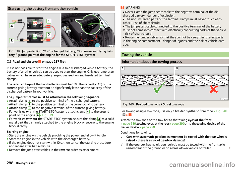
Start using the battery from another vehicleFig. 339
Jump-starting:
- Discharged battery,
- power-supplying bat-
tery / ground point of the engine for the START-STOP system
Read and observe
on page 287 first.
If it is not possible to start the engine due to a discharged vehicle battery, the
battery of another vehicle can be used to start the engine. Only use jump-start
cables which have an adequately large cross-section and insulated terminal
clamps.
The rated voltage of the two batteries must be 12V. The capacity (Ah) of the
current-giving battery must not be significantly less than the capacity of the
discharged battery in your vehicle.
The jump-start cables must be attached in the following sequence.
›
Attach clamp
1
to the positive terminal of the discharged battery.
›
Attach clamp
2
to the positive terminal of the current-giving battery.
›
Attach clamp
3
to the negative terminal of the current-giving battery.
›
For vehicles with the START-STOPsystem, attach clamp
4
to the ground
point of the engine
A
» Fig. 339 .
›
For vehicles without the START-STOP system, secure the clamp
4
to a solid
metal part that is firmly attached to the engine block or secure to the engine
block directly.
Starting engine
›
Start the engine on the vehicle providing the power and allow it to idle.
›
Start the engine in the vehicle with the discharged battery.
›
If the engine does not start within 10 s, then cancel the starting procedure
and repeat after half a minute.
›
Remove the jump start cables in the reverse order as attachment.
WARNING■
Never clamp the jump-start cable to the negative terminal of the dis-
charged battery - danger of explosion.■
The non-insulated parts of the terminal clamps must never touch each
other – risk of short circuit!
■
The jump-start cable connected to the positive terminal of the battery
must not come into contact with electrically conducting parts of the vehicle
– risk of short circuit!
■
Route the jumper cables so that they cannot be caught in rotating parts
in the engine compartment - danger of injuries and the risk of vehicle dam-
age.
Towing the vehicle
Information about the towing process
Fig. 340
Braided tow rope / Spiral tow rope
For towing using a tow rope, use only a braided synthetic fibre rope » Fig. 340
-
»
.
Attach the tow rope or the tow bar to the towing eyes at the front
» page 289 ,towing eyes at the rear » page 290or to thetowing device of the
trailer device » page 250 .
Conditions for towing. Cars with automatic gearboxes must not be towed with the rear wheels
raised - there is a risk of gearbox damage!
If the gearbox has no oil, your vehicle must be towed with the front axle
raised clear of the ground or on a breakdown vehicle or trailer.
288Do-it-yourself
Page 291 of 336
The maximum towing speed is 50 km/h.
The vehicle must be transported on a special breakdown vehicle or trailer
if it is not possible to tow in the vehicle in the way described or if the tow-
ing distance is greater than 50 km.
Driver of the tow vehicle›
On vehicles with manual transmission , engage gear slowly when starting.
›
On vehicles with automatic transmission , accelerate with particular care.
›
Only then approach correctly when the rope is taut.
Driver of the towed vehicle
›
If possible, the vehicle should be towed with the engine running. Operate the
brake booster and power steering only if the engine is running, otherwise
the brake pedal must be depressed more strongly and more power has to be
directed to the steering.
›
If it is not possible to start the engine, switch on the ignition so that the
steering wheel is not locked and so that the turn signal lights, windscreen
wipers and windscreen washer system can be used.
›
Take the vehicle out of gear or move the selector lever into position N if the
vehicle is fitted with an automatic gearbox.
›
Always keep the tow rope taut during the towing procedure.
WARNING■ Wound tow ropes must not be used for towing » Fig. 340- , the towing
eye may unscrew out of the vehicle - risk of accident.■
Ensure tow rope is not twisted - risk of accident.
CAUTION
■ Do not tow-start the engine – risk of damaging the engine! The battery from
another vehicle can be used as a jump-start aid » page 287, Jump-starting .■
In the case of off-road towing manoeuvres, for both vehicles there is the risk
that the fastening parts could be overloaded and damaged.
Note
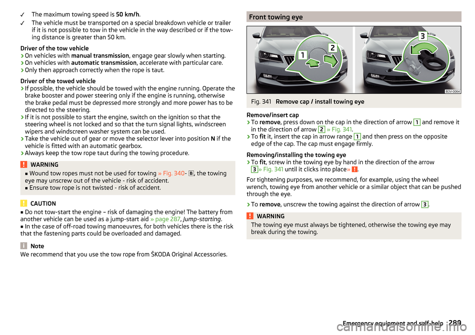
We recommend that you use the tow rope from ŠKODA Original Accessories.Front towing eyeFig. 341
Remove cap / install towing eye
Remove/insert cap
›
To remove , press down on the cap in the direction of arrow
1
and remove it
in the direction of arrow
2
» Fig. 341 .
›
To fit it, insert the cap in arrow range
1
and then press on the opposite
edge of the cap. The cap must engage firmly.
Removing/installing the towing eye
›
To fit, screw in the towing eye by hand in the direction of the arrow
3
» Fig. 341 until it clicks into place » .
For tightening purposes, we recommend, for example, using the wheel
wrench, towing eye from another vehicle or a similar object that can be pushed
through the eye.
›
To remove , unscrew the towing against the direction of arrow
3
.
WARNINGThe towing eye must always be tightened, otherwise the towing eye may
break during the towing.289Emergency equipment and self-help
Page 299 of 336
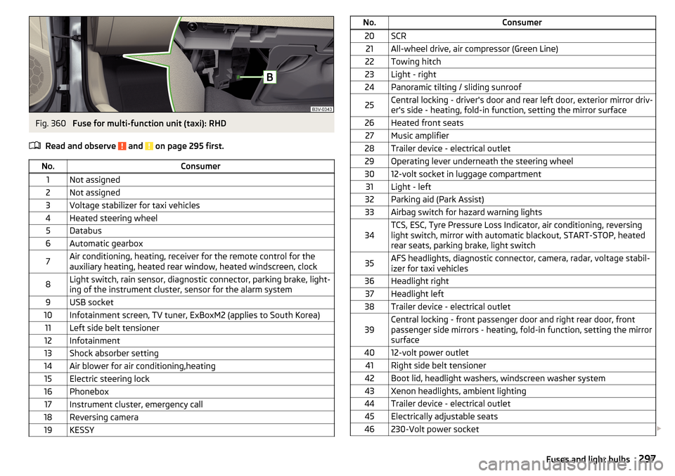
Fig. 360
Fuse for multi-function unit (taxi): RHD
Read and observe
and on page 295 first.
No.Consumer1Not assigned2Not assigned3Voltage stabilizer for taxi vehicles4Heated steering wheel5Databus6Automatic gearbox7Air conditioning, heating, receiver for the remote control for the
auxiliary heating, heated rear window, heated windscreen, clock8Light switch, rain sensor, diagnostic connector, parking brake, light-
ing of the instrument cluster, sensor for the alarm system9USB socket10Infotainment screen, TV tuner, ExBoxM2 (applies to South Korea)11Left side belt tensioner12Infotainment13Shock absorber setting14Air blower for air conditioning,heating15Electric steering lock16Phonebox17Instrument cluster, emergency call18Reversing camera19KESSYNo.Consumer20SCR21All-wheel drive, air compressor (Green Line)22Towing hitch23Light - right24Panoramic tilting / sliding sunroof25Central locking - driver's door and rear left door, exterior mirror driv-
er's side - heating, fold-in function, setting the mirror surface26Heated front seats27Music amplifier28Trailer device - electrical outlet29Operating lever underneath the steering wheel3012-volt socket in luggage compartment31Light - left32Parking aid (Park Assist)33Airbag switch for hazard warning lights34TCS, ESC, Tyre Pressure Loss Indicator, air conditioning, reversing
light switch, mirror with automatic blackout, START-STOP, heated
rear seats, parking brake, light switch35AFS headlights, diagnostic connector, camera, radar, voltage stabil-
izer for taxi vehicles36Headlight right37Headlight left38Trailer device - electrical outlet39Central locking - front passenger door and right rear door, front
passenger side mirrors - heating, fold-in function, setting the mirror
surface4012-volt power outlet41Right side belt tensioner42Boot lid, headlight washers, windscreen washer system43Xenon headlights, ambient lighting44Trailer device - electrical outlet45Electrically adjustable seats46230-Volt power socket 297Fuses and light bulbs
Page 300 of 336
No.Consumer47Rear window wiper48Blind spot detection49Engine starting, clutch pedal switch50Opening the boot lid51Heating of the rear seats52Heated front seats53Heated rear windowA
» Fig. 359Multifunctional unit for taxi vehicles - LHD
B
» Fig. 36 0Multifunctional unit for taxi vehicles - RHD
Fuses in the engine compartment
Fig. 361
Fuse panel cover: Removing / plastic clip for fuses
Read and observe
and on page 295 first.
Replacing fuses
›
Remove the ignition key, turn off the lights and all electrical consumers.
›
Press together the lock buttons of the cover simultaneously in the direction
of arrow
1
and remove the cover in the direction of arrow
2
» Fig. 361 .
›
Remove the plastic clip under the cover of the fuse box » Fig. 361.
›
Use the clip to pull the fuse out, then insert a new fuse.
›
Stow the clamp back in the original position.
›
Replace the cover, push the lock buttons of the cover together and lock.
CAUTIONThe cover of the fuse box in the engine compartment must always be used
correctly, otherwise water may penetrate into the fuse box – there is a danger
of damage to the vehicle!
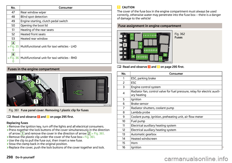
Fuse assignment in engine compartment
Fig. 362
Fuses
Read and observe and on page 295 first.
No.Consumer1ESC, parking brake2ESC3Engine control system4Radiator fan, control valve for fuel pressure, relay for electric auxili-
ary heating5Ignition6Brake sensor7Radiator shutters, coolant pump8Lambda probe9Coolant pump, ignition, preheating unit, air flow meter10Fuel pump11Electrical auxiliary heating system12Electrical auxiliary heating system13Automatic gearbox14Heated windscreen15Horn16Ignition 298Do-it-yourself
Page 305 of 336
Technical data
Technical data
Basic vehicle data
Introduction
This chapter contains information on the following subjects:
Vehicle data
303
Operating weight
304
Payload
305
Measurement of fuel consumption and CO 2 emissions according to ECE
Regulations and EU Directives
305
Dimensions - Superb
306
Dimensions - Superb estate
307
Overhang angle
308
The details given in the vehicle's technical documentation always take prece-
dence over the details in the Owner's Manual.
The listed performance values were determined without performance-reduc- ing equipment, e.g. air conditioning system.
The values given have been determined in accordance with the rules and con-
ditions specified in statutory or technical regulations for determining opera-
tional and technical data for motor vehicles.
The values listed are for the basic model without any optional equipment.
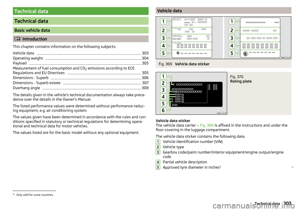
Vehicle dataFig. 369
Vehicle data sticker
Fig. 370
Rating plate
Vehicle data sticker
The vehicle data carrier » Fig. 369 is affixed in the instructions and under the
floor covering in the luggage compartment.
The vehicle data sticker contains the following data. Vehicle identification number (VIN)
Vehicle type
Gearbox code/paint number/interior equipment/engine output/engine
code
Partial vehicle description
Approved tyre diameter in inches 1)
123451)
Only valid for some countries.
303Technical data