key SKODA SUPERB 2016 3.G / (B8/3V) Workshop Manual
[x] Cancel search | Manufacturer: SKODA, Model Year: 2016, Model line: SUPERB, Model: SKODA SUPERB 2016 3.G / (B8/3V)Pages: 336, PDF Size: 53.89 MB
Page 270 of 336
We recommend when refilling using refill bottles that you use refill bottles
from ŠKODA Original Accessories.
When adding AdBlue ®
take note of the minimum and maximum AdBlue ®
tank
capacity shown in the display of the instrument cluster » page 40.
Refill AdBlue ®
under the following conditions.
The vehicle is on a horizontal surface.
The ignition is switched off.
Refilling›
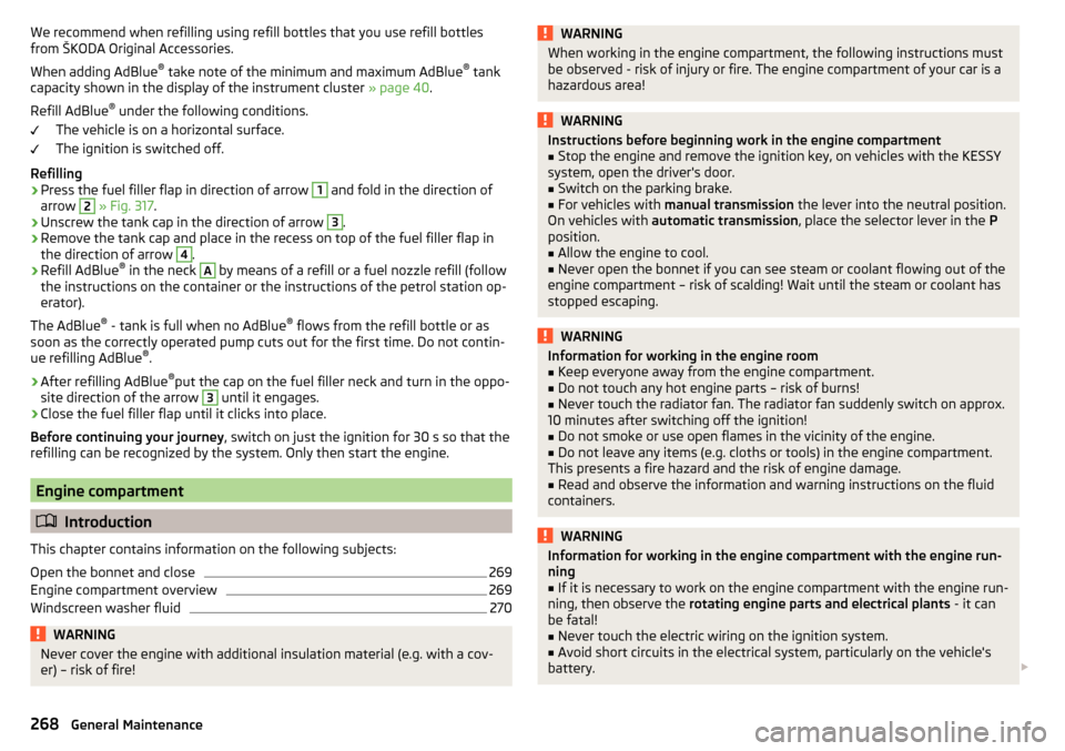
Press the fuel filler flap in direction of arrow
1
and fold in the direction of
arrow
2
» Fig. 317 .
›
Unscrew the tank cap in the direction of arrow
3
.
›
Remove the tank cap and place in the recess on top of the fuel filler flap in
the direction of arrow
4
.
›
Refill AdBlue ®
in the neck
A
by means of a refill or a fuel nozzle refill (follow
the instructions on the container or the instructions of the petrol station op-
erator).
The AdBlue ®
- tank is full when no AdBlue ®
flows from the refill bottle or as
soon as the correctly operated pump cuts out for the first time. Do not contin-
ue refilling AdBlue ®
.
›
After refilling AdBlue ®
put the cap on the fuel filler neck and turn in the oppo-
site direction of the arrow
3
until it engages.
›
Close the fuel filler flap until it clicks into place.
Before continuing your journey , switch on just the ignition for 30 s so that the
refilling can be recognized by the system. Only then start the engine.
Engine compartment
Introduction
This chapter contains information on the following subjects:
Open the bonnet and close
269
Engine compartment overview
269
Windscreen washer fluid
270WARNINGNever cover the engine with additional insulation material (e.g. with a cov-
er) – risk of fire!WARNINGWhen working in the engine compartment, the following instructions must
be observed - risk of injury or fire. The engine compartment of your car is a
hazardous area!WARNINGInstructions before beginning work in the engine compartment■Stop the engine and remove the ignition key, on vehicles with the KESSY
system, open the driver's door.■
Switch on the parking brake.
■
For vehicles with manual transmission the lever into the neutral position.
On vehicles with automatic transmission , place the selector lever in the P
position.
■
Allow the engine to cool.
■
Never open the bonnet if you can see steam or coolant flowing out of the
engine compartment – risk of scalding! Wait until the steam or coolant has
stopped escaping.
WARNINGInformation for working in the engine room■Keep everyone away from the engine compartment.■
Do not touch any hot engine parts – risk of burns!
■
Never touch the radiator fan. The radiator fan suddenly switch on approx.
10 minutes after switching off the ignition!
■
Do not smoke or use open flames in the vicinity of the engine.
■
Do not leave any items (e.g. cloths or tools) in the engine compartment.
This presents a fire hazard and the risk of engine damage.
■
Read and observe the information and warning instructions on the fluid
containers.
WARNINGInformation for working in the engine compartment with the engine run-
ning■
If it is necessary to work on the engine compartment with the engine run-
ning, then observe the rotating engine parts and electrical plants - it can
be fatal!
■
Never touch the electric wiring on the ignition system.
■
Avoid short circuits in the electrical system, particularly on the vehicle's
battery.
268General Maintenance
Page 292 of 336
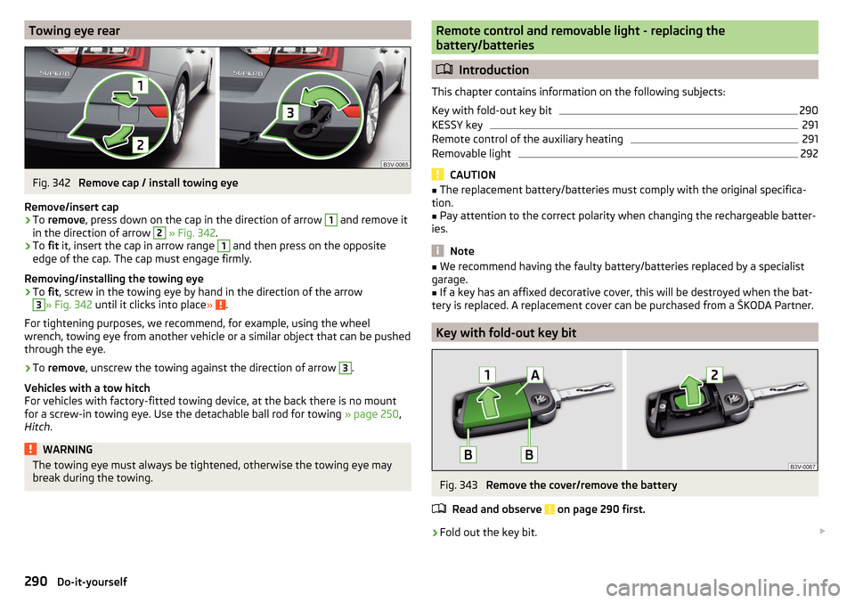
Towing eye rearFig. 342
Remove cap / install towing eye
Remove/insert cap
›
To remove , press down on the cap in the direction of arrow
1
and remove it
in the direction of arrow
2
» Fig. 342 .
›
To fit it, insert the cap in arrow range
1
and then press on the opposite
edge of the cap. The cap must engage firmly.
Removing/installing the towing eye
›
To fit, screw in the towing eye by hand in the direction of the arrow
3
» Fig. 342 until it clicks into place » .
For tightening purposes, we recommend, for example, using the wheel
wrench, towing eye from another vehicle or a similar object that can be pushed
through the eye.
›
To remove , unscrew the towing against the direction of arrow
3
.
Vehicles with a tow hitch
For vehicles with factory-fitted towing device, at the back there is no mount
for a screw-in towing eye. Use the detachable ball rod for towing » page 250,
Hitch .
WARNINGThe towing eye must always be tightened, otherwise the towing eye may
break during the towing.Remote control and removable light - replacing the
battery/batteries
Introduction
This chapter contains information on the following subjects:
Key with fold-out key bit
290
KESSY key
291
Remote control of the auxiliary heating
291
Removable light
292
CAUTION
■ The replacement battery/batteries must comply with the original specifica-
tion.■
Pay attention to the correct polarity when changing the rechargeable batter-
ies.
Note
■ We recommend having the faulty battery/batteries replaced by a specialist
garage.■
If a key has an affixed decorative cover, this will be destroyed when the bat-
tery is replaced. A replacement cover can be purchased from a ŠKODA Partner.
Key with fold-out key bit
Fig. 343
Remove the cover/remove the battery
Read and observe
on page 290 first.
›
Fold out the key bit.
290Do-it-yourself
Page 293 of 336
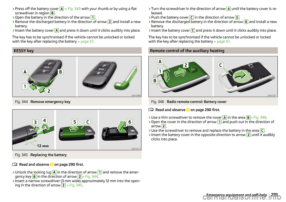
›Press off the battery cover A
» Fig. 343 with your thumb or by using a flat
screwdriver in region B.›
Open the battery in the direction of the arrow
1
.
›
Remove the discharged battery in the direction of arrow
2
and install a new
battery.
›
Insert the battery cover
A
and press it down until it clicks audibly into place.
The key has to be synchronised if the vehicle cannot be unlocked or locked
with the key after replacing the battery » page 57.
KESSY key
Fig. 344
Remove emergency key
Fig. 345
Replacing the battery
Read and observe
on page 290 first.
›
Unlock the locking lug
A
in the direction of arrow
1
and remove the emer-
gency key
B
in the direction of arrow
2
» Fig. 344 .
›
Insert a narrow screwdriver (3 mm wide) approximately 12 mm into the open-
ing in the direction of arrow
3
» Fig. 345 .
›Turn the screwdriver in the direction of arrow 4 until the battery cover is re-
leased.›
Push the battery cover
C
in the direction of arrow
5
.
›
Remove the discharged battery in the direction of arrow
6
and install a new
battery.
›
Insert the battery cover
C
and press it down until it clicks audibly into place.
The key has to be synchronised if the vehicle cannot be unlocked or locked
with the key after replacing the battery » page 57.
Remote control of the auxiliary heating
Fig. 346
Radio remote control: Battery cover
Read and observe
on page 290 first.
›
Use a thin screwdriver to remove the cover
A
in the area
B
» Fig. 346 .
›
Open the cover in the direction of arrow
1
and push out in the direction of
arrow
2
.
›
Use the screwdriver to remove and replace the battery in the area
C
.
›
Insert the battery cover in the opposite direction to arrow
2
until it audibly
clicks into place.
291Emergency equipment and self-help
Page 294 of 336
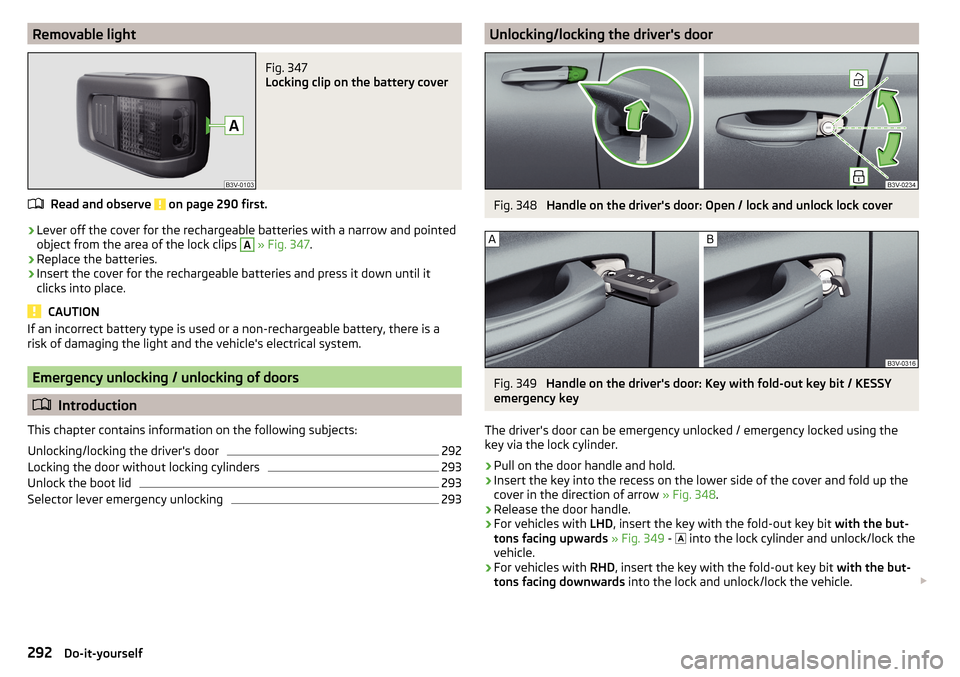
Removable lightFig. 347
Locking clip on the battery cover
Read and observe on page 290 first.
›
Lever off the cover for the rechargeable batteries with a narrow and pointed
object from the area of the lock clips
A
» Fig. 347 .
›
Replace the batteries.
›
Insert the cover for the rechargeable batteries and press it down until it
clicks into place.
CAUTION
If an incorrect battery type is used or a non-rechargeable battery, there is a
risk of damaging the light and the vehicle's electrical system.
Emergency unlocking / unlocking of doors
Introduction
This chapter contains information on the following subjects:
Unlocking/locking the driver's door
292
Locking the door without locking cylinders
293
Unlock the boot lid
293
Selector lever emergency unlocking
293Unlocking/locking the driver's doorFig. 348
Handle on the driver's door: Open / lock and unlock lock cover
Fig. 349
Handle on the driver's door: Key with fold-out key bit / KESSY
emergency key
The driver's door can be emergency unlocked / emergency locked using the
key via the lock cylinder.
›
Pull on the door handle and hold.
›
Insert the key into the recess on the lower side of the cover and fold up the
cover in the direction of arrow » Fig. 348.
›
Release the door handle.
›
For vehicles with LHD, insert the key with the fold-out key bit with the but-
tons facing upwards » Fig. 349 -
into the lock cylinder and unlock/lock the
vehicle.
›
For vehicles with RHD, insert the key with the fold-out key bit with the but-
tons facing downwards into the lock and unlock/lock the vehicle.
292Do-it-yourself
Page 295 of 336
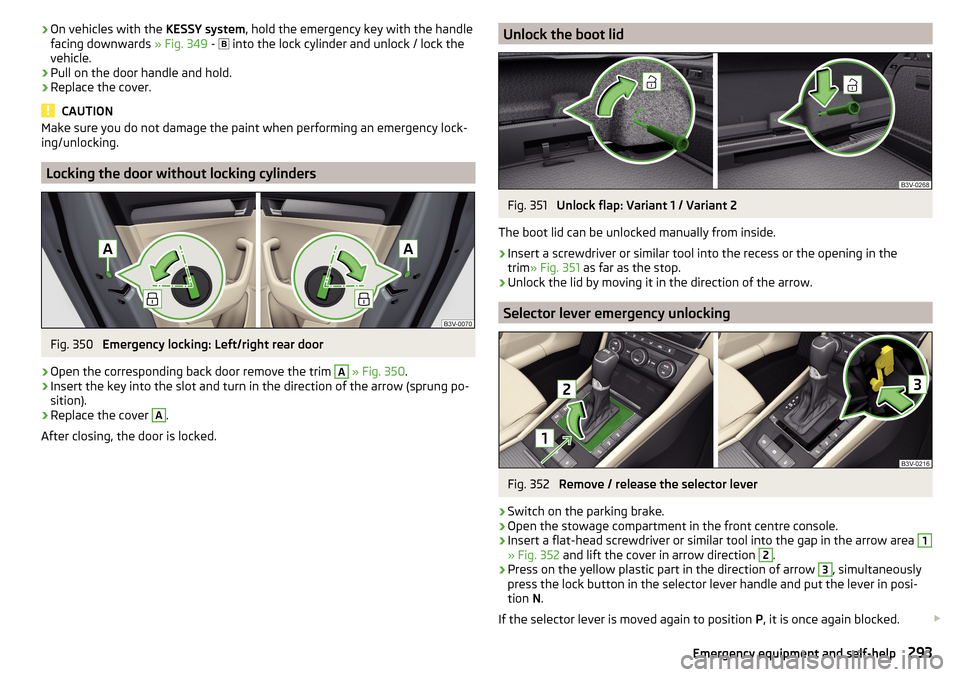
›On vehicles with the
KESSY system, hold the emergency key with the handle
facing downwards » Fig. 349 - into the lock cylinder and unlock / lock the
vehicle.›
Pull on the door handle and hold.
›
Replace the cover.
CAUTION
Make sure you do not damage the paint when performing an emergency lock-
ing/unlocking.
Locking the door without locking cylinders
Fig. 350
Emergency locking: Left/right rear door
›
Open the corresponding back door remove the trim
A
» Fig. 350 .
›
Insert the key into the slot and turn in the direction of the arrow (sprung po-
sition).
›
Replace the cover
A
.
After closing, the door is locked.
Unlock the boot lidFig. 351
Unlock flap: Variant 1 / Variant 2
The boot lid can be unlocked manually from inside.
›
Insert a screwdriver or similar tool into the recess or the opening in the
trim » Fig. 351 as far as the stop.
›
Unlock the lid by moving it in the direction of the arrow.
Selector lever emergency unlocking
Fig. 352
Remove / release the selector lever
›
Switch on the parking brake.
›
Open the stowage compartment in the front centre console.
›
Insert a flat-head screwdriver or similar tool into the gap in the arrow area
1
» Fig. 352 and lift the cover in arrow direction
2
.
›
Press on the yellow plastic part in the direction of arrow
3
, simultaneously
press the lock button in the selector lever handle and put the lever in posi-
tion N.
If the selector lever is moved again to position P, it is once again blocked.
293Emergency equipment and self-help
Page 298 of 336
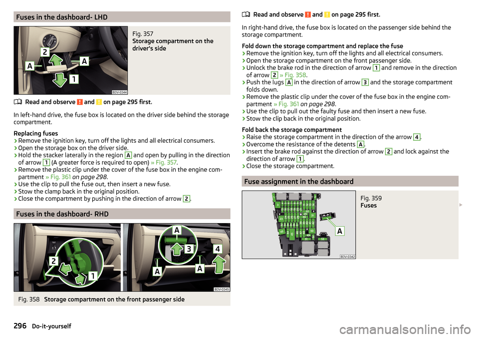
Fuses in the dashboard- LHDFig. 357
Storage compartment on the
driver's side
Read and observe and on page 295 first.
In left-hand drive, the fuse box is located on the driver side behind the storage compartment.
Replacing fuses
›
Remove the ignition key, turn off the lights and all electrical consumers.
›
Open the storage box on the driver side.
›
Hold the stacker laterally in the region
A
and open by pulling in the direction
of arrow
1
(A greater force is required to open) » Fig. 357.
›
Remove the plastic clip under the cover of the fuse box in the engine com-
partment » Fig. 361 on page 298 .
›
Use the clip to pull the fuse out, then insert a new fuse.
›
Stow the clamp back in the original position.
›
Close the compartment by pushing in the direction of arrow
2
.
Fuses in the dashboard- RHD
Fig. 358
Storage compartment on the front passenger side
Read and observe and on page 295 first.
In right-hand drive, the fuse box is located on the passenger side behind the
storage compartment.
Fold down the storage compartment and replace the fuse
›
Remove the ignition key, turn off the lights and all electrical consumers.
›
Open the storage compartment on the front passenger side.
›
Unlock the brake rod in the direction of arrow
1
and remove in the direction
of arrow
2
» Fig. 358 .
›
Push the lugs
A
in the direction of arrow
3
and the storage compartment
folds down.
›
Remove the plastic clip under the cover of the fuse box in the engine com-
partment » Fig. 361 on page 298 .
›
Use the clip to pull out the faulty fuse and then insert a new fuse.
›
Stow the clip back in the original position.
Fold back the storage compartment
›
Raise the storage compartment in the direction of the arrow
4
.
›
Overcome the resistance of the detents
A
.
›
Insert the brake rod against the direction of arrow
2
and lock against the
direction of arrow
1
.
›
Close the storage compartment.
Fuse assignment in the dashboard
Fig. 359
Fuses
296Do-it-yourself
Page 300 of 336
No.Consumer47Rear window wiper48Blind spot detection49Engine starting, clutch pedal switch50Opening the boot lid51Heating of the rear seats52Heated front seats53Heated rear windowA
» Fig. 359Multifunctional unit for taxi vehicles - LHD
B
» Fig. 36 0Multifunctional unit for taxi vehicles - RHD
Fuses in the engine compartment
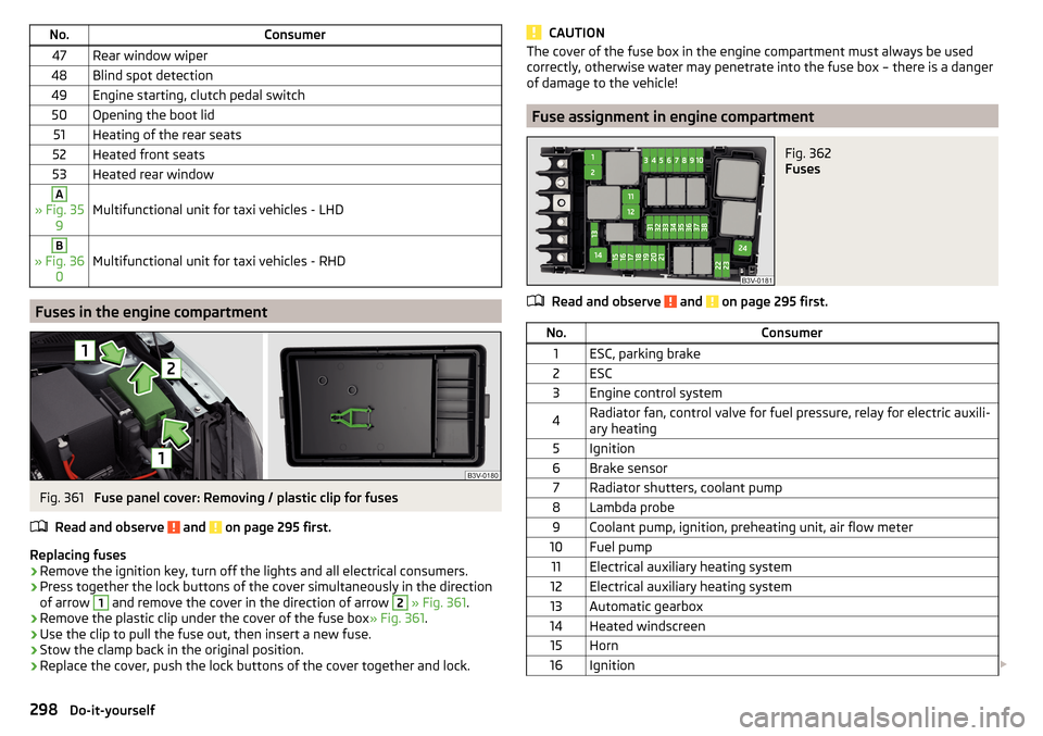
Fig. 361
Fuse panel cover: Removing / plastic clip for fuses
Read and observe
and on page 295 first.
Replacing fuses
›
Remove the ignition key, turn off the lights and all electrical consumers.
›
Press together the lock buttons of the cover simultaneously in the direction
of arrow
1
and remove the cover in the direction of arrow
2
» Fig. 361 .
›
Remove the plastic clip under the cover of the fuse box » Fig. 361.
›
Use the clip to pull the fuse out, then insert a new fuse.
›
Stow the clamp back in the original position.
›
Replace the cover, push the lock buttons of the cover together and lock.
CAUTIONThe cover of the fuse box in the engine compartment must always be used
correctly, otherwise water may penetrate into the fuse box – there is a danger
of damage to the vehicle!
Fuse assignment in engine compartment
Fig. 362
Fuses
Read and observe and on page 295 first.
No.Consumer1ESC, parking brake2ESC3Engine control system4Radiator fan, control valve for fuel pressure, relay for electric auxili-
ary heating5Ignition6Brake sensor7Radiator shutters, coolant pump8Lambda probe9Coolant pump, ignition, preheating unit, air flow meter10Fuel pump11Electrical auxiliary heating system12Electrical auxiliary heating system13Automatic gearbox14Heated windscreen15Horn16Ignition 298Do-it-yourself
Page 303 of 336
Changing light bulbs for fog lightsFig. 366
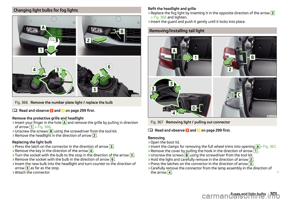
Remove the number plate light / replace the bulb
Read and observe
and on page 299 first.
Remove the protective grille and headlight
›
Insert your finger in the hole
A
and remove the grille by pulling in direction
of arrow
1
» Fig. 366 .
›
Unscrew the screws
B
using the screwdriver from the tool kit.
›
Remove the headlight in the direction of arrow
2
.
Replacing the light bulb
›
Press the latch on the connector in the direction of arrow
3
.
›
Remove the key in the direction of the arrow
4
.
›
Turn the socket with the bulb to the stop in the direction of the arrow
5
.
›
Remove the socket with the bulb in the direction of arrow
6
.
›
Insert the new bulb into the headlight and turn counter to the direction of
arrow
5
as far as the stop.
›
Attach the connector.
Refit the headlight and grille›Replace the fog light by inserting it in the opposite direction of the arrow 2
» Fig. 366 and tighten.
›
Insert the guard and push it gently until it locks into place.
Removing/installing tail light
Fig. 367
Removing light / pulling out connector
Read and observe
and on page 299 first.
Removing
›
Open the boot lid.
›
Insert the clamps for removing the full wheel trims into opening
A
» Fig. 367 .
›
Remove the cover by pulling the hook in the direction of arrow
1
.
›
Unscrew the screws
B
using the screwdriver from the tool kit.
›
Hold the light and carefully remove in the direction of arrow
2
.
›
Press the latches on the connector in the direction of arrow
3
.
›
Carefully remove the connector from the lamp assembly in the direction of
the arrow
4
.
301Fuses and light bulbs
Page 315 of 336
Index
A
A2DP/AVRCP
164
Abort route guidance192
ABS Operation
213
Warning light36
ACC233
Settings in Infotainment233
Acceptance and recycling of used vehicles258
Accessories256
Active steering assist (DSR)214
Adaptive Chassis Control Warning light
42
Adaptive Chassis Control (DCC)240
Adaptive cruise control Operation
234
Set/change the desired speed236
Start control235
Warning light35, 42
Adaptive cruise Control Settings in Infotainment
233
Adaptive Cruise Control233
automatic stopping and starting234
Malfunctions237
Operation overview235
Overtaking237
Radar sensor212
Set the clearance level236
Special driving situations236
Stop/resume control235
Trailer towing237
Adaptive headlight see xenon headlight
69
AdBlue267
Check level267
refill267
Warning light40
Additional keypad languages132, 140
Additional windows Audio
182
Compass182
Manoeuvre182
Map182
Menus182
Most frequent routes182
Satellite data182
Turn on/off182
Waypoint tour182
Adjusting Steering wheel
13
Adjusting seats manually80
Adjusting the seats12
Advice on tyre/wheel usage276
AHL See xenon headlight
69
Aim Enter destination using the address
183
Air-conditioning system Air outlet vents
117
Airbag18
Adjustments and impairments on the airbag system
257
Deactivation21
Deployment19
Warning light37
Airbag system18
Air conditioning113
Air distribution control117
Climatronic114
Manual air conditioning114
Air distribution control117
Air outlet vents117
Alarm58
Trailer255
All season tyres278
Alphanumeric with keyboard126
Alternative routes137
Ambient lighting73
Android Auto177
Connection establishment177
Disconnection177
Main menu177
Anti-lock braking system (ABS)213
Anti-theft alarm system58
Trailer255
Anti-theft wheel bolts284
APN133
Apple CarPlay178
Connection establishment178
Disconnection178
Main menu178
Armrest Front
82
rear94
Rear83
Ashtray98
Assistant for emergencies246
Assist systems212
AT THE142, 143
Audio source149
Auto Check Control44
Auto Hold204
Warning light39
Auto Hold function204
Warning light39
Automatic consumer shutdown273
Automatic drive Kickdown
208
Selector lever207
Automatic driving light control68
Automatic gearbox Launch control
209
Malfunction39
Manual shifting on the multifunction steering wheel
208
Release gear selector lever207
313Index
Page 316 of 336
Selector lever emergency unlocking293
Selector lever lock207
Start and run208
Tiptronic208
Warning light39
Automatic transmission206
AUX90, 150
Settings135
Auxiliary heating (auxiliary heating and ventila- tion)
118
Avoiding damage to your vehicle211
B
Battery Changing batteries for the removable light
292
Changing in key290, 291
Replace the battery in the remote control in the auxiliary heating
291
Belts15
Belt tensioners17
Bluetooth A2DP / AVRCP
133
Name133
on / off133
Paired external devices133
rSAP167
Set140
set to133, 136
Set to133
Switch on/off140
Update131, 134
Updates140
Visibility133, 140
Bluetooth Player151
Bluetooth profile164
Bluetooth® update164
Bonnet Close
269
Open269
Boot Class N1 vehicles109
Boot lid59
Automatic locking59
Contactless open/close61
Open/close59, 60
See boot lid59
Boot lid contactless open/close61
Brake Assist (HBA)214
Brake booster203
Brake fluid273
Check273
specification273
Brake linings Warning light
38
Brake pads new
203
Brake pedal (automatic gearbox) Warning light
38
Brakes Brake booster
203
Brake fluid273
Braking and stabilisation systems212
Information on braking203
Parking brake203
Running in209
Warning light35
Brake system212
Breakdown call168
Broadcasting143
See main menu142
Bulbs Replacing
299
Buttons on the driver door Electric windows
62
C
Call list Call list
170
CameraSee reversing camera221
CAR198
Car battery automatic consumer shutdown
273
Check condition274
Cover274
Disconnecting and reconnecting275
Replacing275
Winter operation274
CAR button198
Car care260
Exterior263
Interior263
Car computer see multifunction display
46
Care and maintenance256
Cargo element106
CAR menu198
Car park184
Carrier112
Car wash260
Exterior263
Panes263
CD149
Central locking53
Problems57
Central locking button55
Changing Batteries for the removable light
292
Battery290, 291
Wheels282
Windscreen wiper blades295
Changing a wheel282
Changing gear Selector lever
207
Tiptronic208
Charging a vehicle battery275
314Index