key SKODA YETI 2009 1.G / 5L Owner's Manual
[x] Cancel search | Manufacturer: SKODA, Model Year: 2009, Model line: YETI, Model: SKODA YETI 2009 1.G / 5LPages: 271, PDF Size: 16.24 MB
Page 4 of 271
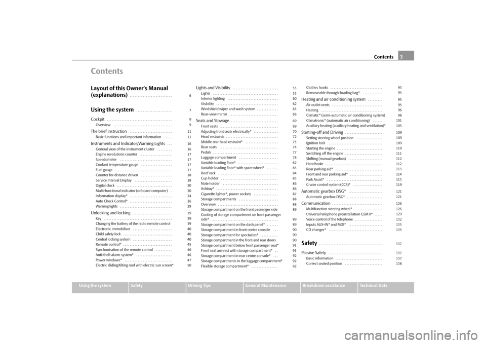
Contents3
Using the system
Safety
Driving Tips
General Maintenance
Breakdown assistance
Technical Data
ContentsLayout of this Owner's Manual
(explanations)
. . . . . . . . . . . . . . . . . . . . . . . . . .
Using the system
. . . . . . . . . . . . . . . . . . . . . .
Cockpit
. . . . . . . . . . . . . . . . . . . . . . . . . . . . . . . . . . . . . . . .
Overview . . . . . . . . . . . . . . . . . . . . . . . . . . . . . . . . . . . .
The brief instruction
. . . . . . . . . . . . . . . . . . . . . . . . . .
Basic functions and important information . . . . .
Instruments and Indicator/Warning Lights
. . .
General view of the instrument cluster . . . . . . . . .
Engine revolutions counter . . . . . . . . . . . . . . . . . . . .
Speedometer . . . . . . . . . . . . . . . . . . . . . . . . . . . . . . . .
Coolant temperature gauge . . . . . . . . . . . . . . . . . . .
Fuel gauge . . . . . . . . . . . . . . . . . . . . . . . . . . . . . . . . . . .
Counter for distance driven . . . . . . . . . . . . . . . . . . .
Service Interval Display . . . . . . . . . . . . . . . . . . . . . . .
Digital clock . . . . . . . . . . . . . . . . . . . . . . . . . . . . . . . . . .
Multi-functional indicator (onboard computer) .
Information display* . . . . . . . . . . . . . . . . . . . . . . . . . .
Auto Check Control* . . . . . . . . . . . . . . . . . . . . . . . . . .
Warning lights . . . . . . . . . . . . . . . . . . . . . . . . . . . . . . . .
Unlocking and locking
. . . . . . . . . . . . . . . . . . . . . . . .
Key . . . . . . . . . . . . . . . . . . . . . . . . . . . . . . . . . . . . . . . . . .
Changing the battery of the radio remote control
Electronic immobiliser . . . . . . . . . . . . . . . . . . . . . . . .
Child safety lock . . . . . . . . . . . . . . . . . . . . . . . . . . . . . .
Central locking system . . . . . . . . . . . . . . . . . . . . . . . .
Remote control* . . . . . . . . . . . . . . . . . . . . . . . . . . . . . .
Synchonisation of the remote control . . . . . . . . . .
Anti-theft alarm system* . . . . . . . . . . . . . . . . . . . . . .
Power windows* . . . . . . . . . . . . . . . . . . . . . . . . . . . . .
Electric sliding/tilting roof with electric sun screen*
Lights and Visibility
. . . . . . . . . . . . . . . . . . . . . . . . . . . .
Lights . . . . . . . . . . . . . . . . . . . . . . . . . . . . . . . . . . . . . . . .
Interior lighting . . . . . . . . . . . . . . . . . . . . . . . . . . . . . . .
Visibility . . . . . . . . . . . . . . . . . . . . . . . . . . . . . . . . . . . . . .
Windshield wiper and wash system . . . . . . . . . . . . .
Rear-view mirror . . . . . . . . . . . . . . . . . . . . . . . . . . . . . .
Seats and Stowage
. . . . . . . . . . . . . . . . . . . . . . . . . . . . .
Front seats . . . . . . . . . . . . . . . . . . . . . . . . . . . . . . . . . . . .
Adjusting front seats electrically* . . . . . . . . . . . . . . .
Head restraints . . . . . . . . . . . . . . . . . . . . . . . . . . . . . . . .
Middle rear head restraint* . . . . . . . . . . . . . . . . . . . .
Rear seats . . . . . . . . . . . . . . . . . . . . . . . . . . . . . . . . . . . .
Pedals . . . . . . . . . . . . . . . . . . . . . . . . . . . . . . . . . . . . . . . .
Luggage compartment . . . . . . . . . . . . . . . . . . . . . . . .
Variable loading floor* . . . . . . . . . . . . . . . . . . . . . . . . .
Variable loading floor* with spare wheel* . . . . . . .
Roof rack . . . . . . . . . . . . . . . . . . . . . . . . . . . . . . . . . . . . .
Cup holder . . . . . . . . . . . . . . . . . . . . . . . . . . . . . . . . . . .
Note holder . . . . . . . . . . . . . . . . . . . . . . . . . . . . . . . . . .
Ashtray* . . . . . . . . . . . . . . . . . . . . . . . . . . . . . . . . . . . . . .
Cigarette lighter*, power sockets . . . . . . . . . . . . . . .
Storage compartments . . . . . . . . . . . . . . . . . . . . . . . .
Overview . . . . . . . . . . . . . . . . . . . . . . . . . . . . . . . . . . . . .
Storage compartment on the front passenger side
Cooling of storage compartment on front passenger
side* . . . . . . . . . . . . . . . . . . . . . . . . . . . . . . . . . . . . . . . . .
Storage compartment on the dash panel* . . . . . . .
Storage compartment in front centre console . . .
Storage compartment for spectacles* . . . . . . . . . . .
Storage compartment in the front and rear doors
Storage compartment below front passenger seat*
Front seat armrest with storage compartment* . .
Storage compartment in rear centre console* . . .
Storage compartments in the luggage compartment*
Flexible storage compartment* . . . . . . . . . . . . . . . .Clothes hooks . . . . . . . . . . . . . . . . . . . . . . . . . . . . . . . .
Removeable through-loading bag* . . . . . . . . . . . .
Heating and air conditioning system
. . . . . . . . .
Air outlet vents . . . . . . . . . . . . . . . . . . . . . . . . . . . . . . .
Heating . . . . . . . . . . . . . . . . . . . . . . . . . . . . . . . . . . . . . .
Climatic* (semi-automatic air conditioning system)
Climatronic* (automatic air conditioning) . . . . . .
Auxiliary heating (auxiliary heating and ventilation)*
Starting-off and Driving
. . . . . . . . . . . . . . . . . . . . . . .
Setting steering wheel position . . . . . . . . . . . . . . . .
Ignition lock . . . . . . . . . . . . . . . . . . . . . . . . . . . . . . . . . .
Starting the engine . . . . . . . . . . . . . . . . . . . . . . . . . . . .
Switching off the engine . . . . . . . . . . . . . . . . . . . . . . .
Shifting (manual gearbox) . . . . . . . . . . . . . . . . . . . . .
Handbrake . . . . . . . . . . . . . . . . . . . . . . . . . . . . . . . . . . .
Rear parking aid* . . . . . . . . . . . . . . . . . . . . . . . . . . . . .
Front and rear parking aid* . . . . . . . . . . . . . . . . . . . .
Park Assist* . . . . . . . . . . . . . . . . . . . . . . . . . . . . . . . . . .
Cruise control system (CCS)* . . . . . . . . . . . . . . . . . .
Automatic gearbox DSG*
. . . . . . . . . . . . . . . . . . . . .
Automatic gearbox DSG* . . . . . . . . . . . . . . . . . . . . . .
Communication
. . . . . . . . . . . . . . . . . . . . . . . . . . . . . . .
Multifunction steering wheel* . . . . . . . . . . . . . . . . .
Universal telephone preinstallation GSM II* . . . . .
Voice control of the telephone . . . . . . . . . . . . . . . . .
Inputs AUX-IN* and MDI* . . . . . . . . . . . . . . . . . . . . .
CD changer* . . . . . . . . . . . . . . . . . . . . . . . . . . . . . . . . .
Safety
. . . . . . . . . . . . . . . . . . . . . . . . . . . . . . . . . . . . . . .
Passive Safety
. . . . . . . . . . . . . . . . . . . . . . . . . . . . . . . . .
Basic information . . . . . . . . . . . . . . . . . . . . . . . . . . . . .
Correct seated position . . . . . . . . . . . . . . . . . . . . . . . 6
7
9
9
11
11
16
16
17
17
17
17
18
18
20
20
24
26
29
39
39
39
40
40
40
45
46
46
47
5053
53
60
62
63
66
69
69
70
72
73
74
77
78
82
83
84
85
86
86
87
88
88
89
89
89
90
90
90
91
91
92
92
9293
93
95
95
96
98
101
105
109
109
109
110
111
112
112
113
114
115
119
121
121
126
126
129
132
135
135
137
137
137
138
sgg.6.book Page 3 Thursday, September 24, 2009 2:32 PM
Page 12 of 271

The brief instruction
11
Using the system
Safety
Driving Tips
General Maintenance
Breakdown assistance
Technical Data
The brief instructionBasic functions and im
portant information
Introduction The chapter of the brief instruction is
only used as a quick reference of
the most important operating elements of the vehicle. It is necessary to observe all the information which is contained in the following chapters of the Owner's Manual.Unlocking and locking the vehicle Unlocking the vehicle Unlocking the boot lid Locking the vehicle Folding out/folding up of the keyFurther information
⇒page 45, “Unlocking and locking car”.
Setting steering wheel positionFig. 3 Adjustable steering wheel: Lever on the
steering column / the correct distance of the
driver from the steering wheelYou can set the height and the forward/back position of the steering wheel to the desired position. – Pull the lever below the steering column
⇒fig. 3
down.
– Set the steering wheel to the desired position (concerning height and forward/back
position).
– Push the lever upwards as far as the stop. Further information
⇒page 109, “Setting steering wheel position”.
WARNING
•
Adjust the steering wheel
so that the distance be
tween the steering wheel
and your chest is at least 25 cm
⇒fig. 3
on the right. Not maintaining this
minimum distance will mean that the airbag system will not be able to properly protect you - hazard!•
You must not adjust the steering wh
eel when the vehicle is moving!
•
For safety reasons the lever must always be firmly pushed up to avoid the
steering wheel altering its position uni
ntentionally when driving - risk of
accident!
Fig. 2 Remote control key
A1A2A3A4
sgg.6.book Page 11 Thursday, September 24, 2009 2:32 PM
Page 15 of 271
The brief instruction
14
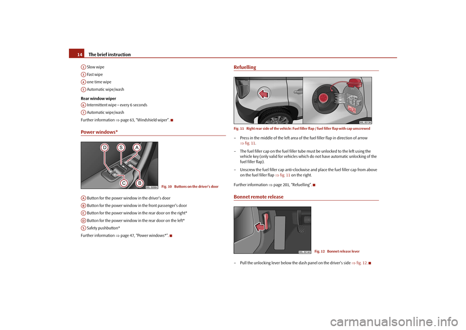
Slow wipe Fast wipe one time wipe Automatic wipe/wash Rear window wiper Intermittent wipe - every 6 seconds Automatic wipe/washFurther information
⇒page 63, “Windshield wiper”.
Power windows* Button for the power window in the driver's door Button for the power window in the front passenger's door Button for the power window in the rear door on the right* Button for the power window in the rear door on the left* Safety pushbutton*Further information
⇒page 47, “Power windows*”.
RefuellingFig. 11 Right rear side of the vehicle: Fuel
filler flap / fuel filler flap with cap unscrewed
– Press in the middle of the left area of the fuel filler flap in direction of arrow
⇒ fig. 11
.
– The fuel filler cap on the fuel filler tube
must be unlocked to the left using the
vehicle key (only valid for vehicles which
do not have automatic unlocking of the
fuel filler flap).
– Unscrew the fuel filler ca
p anti-clockwise and place the fuel filler cap from above
on the fuel filler flap
⇒fig. 11
on the right.
Further information
⇒page 201, “Refuelling”.
Bonnet remote release– Pull the unlocking lever below the dash panel on the driver's side
⇒fig. 12
.
A2A3A4A5A6A7
Fig. 10 Buttons on the driver's door
AAABACADAS
Fig. 12 Bonnet release lever
sgg.6.book Page 14 Thursday, September 24, 2009 2:32 PM
Page 19 of 271
Instruments and Indicator/Warning Lights
18
Caution
Never run the fuel tank completely empty!
The irregular supply of the fuel system can
lead to irregular running of
the engine. Unburnt fuel may get into the exhaust system
and damage the catalytic converter.
Note
After filling up, it can occur that during dy
namic driving (e.g. numerous curves, braking,
driving downhill and climbing a steep hill) the fuel gauge indicates approx. a fraction less. When stopping or during less dynamic
driving, the correct fuel supply quantity is
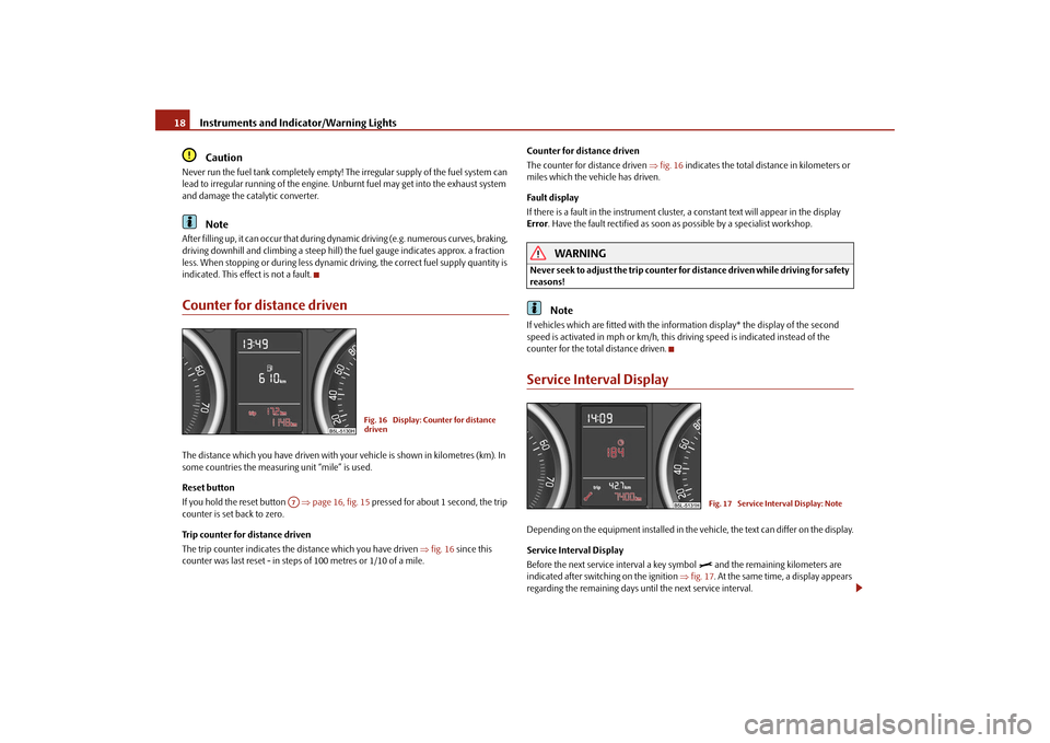
indicated. This effect is not a fault.Counter for distance drivenThe distance which you have driven with yo
ur vehicle is shown in kilometres (km). In
some countries the measuring unit “mile” is used. Reset button If you hold the reset button
⇒page 16, fig. 15
pressed for about 1 second, the trip
counter is set back to zero. Trip counter for distance driven The trip counter indicates the distance which you have driven
⇒fig. 16
since this
counter was last reset - in steps of 100 metres or 1/10 of a mile.
Counter for distance driven The counter for distance driven
⇒fig. 16
indicates the total distance in kilometers or
miles which the ve
hicle has driven.
Fa ult di spl ay If there is a fault in the inst
rument cluster, a co
nstant text will appear in the display
Error
. Have the fault rectified as soon as possible by a specialist workshop.WARNING
Never seek to adjust the trip counter for
distance driven while driving for safety
reasons!
Note
If vehicles which are fitted with the info
rmation display* the display of the second
speed is activated in mph or km/h, this driving speed is indicated instead of the counter for the total distance driven.Service Interval DisplayDepending on the equipment installed in the vehicle, the text can differ on the display. Service Interval Display Before the next service interval a key symbol
and the remaining kilometers are
indicated after switching on the ignition
⇒fig. 17
. At the same time, a display appears
regarding the remaining days until the next service interval.
Fig. 16 Display: Co
unter for distance
driven
A7
Fig. 17 Service Interval Display: Note
sgg.6.book Page 18 Thursday, September 24, 2009 2:32 PM
Page 20 of 271
Instruments and Indicator/Warning Lights
19
Using the system
Safety
Driving Tips
General Maintenance
Breakdown assistance
Technical Data
The following will be displayed in the information display*:
Service in ... km or... days
The kilometre indicator or the days indicator reduces in steps of 100 km. or days until the service due date is reached. A flashing key symbol
and the text
Service
appears in the display for 20 seconds
as soon as the due date for the service is reached. The following will be displayed in the information display*:
Service now!
Display regarding the distance and days until the following service interval You can use the button to display the remaining distance driven and the days until the next service interval
⇒page 16.
A key symbol
and a display regarding the remaining kilometers appear for 10
second in the display. At the same time, a display appears regarding the remaining days until the next service interval. On vehicles which are equipped with inform
ation display*, you ca
n call up this infor-
mation in the following menu on
⇒page 24:
�„
SETUP (Settings)
�„
Service Interval (Service)
�„
Info
The following will be displayed in the information display* for 10 seconds:
Service in ... km or... days
Resetting Service Interval Display It is only possible to reset the Service Interval Display, if a service message or at least a pre-warning is shown on the display of the instrument cluster. We recommend having this resetting performed by a specialist garage.The specialist garage:•
resets the memory of the display after the appropriate inspection;
•
makes an entry in the Service schedule;
•
affix the sticker with the entry of the following service interval to the side of the
dash panel on the driver's side. Reset the service interval displays by using the reset button
⇒page 16 on the trip
counter. On vehicles which are equipped
with information display*, you can call up this infor-
mation in the following menu on
⇒page 24:
�„
SETTINGS
�„
Service Interval (Service)
�„
ResetCaution
We recommend that you do not reset the Se
rvice Interval Display yourself otherwise
this can result in the service interval displa
y being incorrectly set, which may also result
in problems with operation of your vehicle.
Note
•
Never reset the display between service intervals otherwise this may result in
incorrect readouts.•
information is retained in the Service Inte
rval Display also after the battery of the
vehicle is disconnected.•
If the instrument cluster is exchanged after a repair, the correct values must be
entered in the counter for the Service Interval
Display. This work is carried out by a
specialist garage.•
The data displayed is the same after resetting the display with flexible service inter-
vals (QG1) using the reset button as that for a vehicle with fixed service intervals (QG2). We therefore recommend having the Service In
terval Display reset
only by an author-
ised Škoda Service Partner who is familiar with the procedure for resetting the display with a vehicle system tester.•
Please refer to the brochure Service schedule for extensive information about the
service intervals.
A3
A7
sgg.6.book Page 19 Thursday, September 24, 2009 2:32 PM
Page 21 of 271

Instruments and Indicator/Warning Lights
20Digital clockThe time is set with the buttons and
⇒page 16, fig. 15
.
Select the display which you wish to chan
ge with the button and carry out the
change with the button . On vehicles which are fitted out with the info
rmation display*, it is possible to set the
time in the menu
Time
⇒page 27.
WARNING
The clock should not be adjusted while dr
iving for safety reasons but only when
the vehicle is stationary!Multi-functional indicator (onboard computer)IntroductionThe multi-functional indicator appears in the display
⇒fig. 18
or in the information
display
⇒page 24 depending on the equipm
ent fitted to your vehicle.
The multi-functional indicator offers
you a range of us
eful information.
On vehicles which are fitted ou
t with information display*, it is possible to switch off
the display of some information.
Caution
Pull out the ignition key while having co
ntact with the display (for example when
cleaning) in order to prevent any damage.
Note
•
In certain national versions the displays appear in the Imperial system of measures.
•
If the display of the second speed is acti
vated in mph, the current speed* is not
indicated in km/h on the display.MemoryThe multi-functional indicator is equi
pped with two automatic memories. The
selected memory is displayed in
the middle of the display field
⇒fig. 18
.
The data of the single-trip memory (memory 1) is shown if a
1 appears in the display.
A 2 shown in the display means that data
relates to the total distance memory
(memory 2). Switching over the memory with the help of the button
⇒page 21, fig. 19
on the
windscreen wiper lever or with the help of the button on the multifunction steering wheel*
⇒page 21.
The outside temperature
⇒page 22
Driving time
⇒page 22
Current fuel consumption
⇒page 22
Average fuel consumption
⇒page 22
Range
⇒page 22
Distance driven
⇒page 23
Average speed
⇒page 23
Current speed*
⇒page 23
Oil temperature
⇒page 23
Warning against excessive speeds*
⇒page 23
A3
A7
A3
A7
Fig. 18 Multi-functional indicator
AB
AD
sgg.6.book Page 20 Thursday, September 24, 2009 2:32 PM
Page 25 of 271

Instruments and Indicator/Warning Lights
24Information display*IntroductionThe information display provides you with information in a convenient way concerning the
current operating state of your vehicle
. The information system also
provides you with data (depending on the equipment installed in the vehicle) relating to the radio, mobile phone, multi-function
al indicator, naviga
tion system, the unit
connected to the MDI input and the automatic gearbox. Certain functions and operating conditions
are always being checked on the vehicle
when the ignition is switched on and also while driving. Functional faults, if required
repair work and other information are indicated by red
symbols
⇒page 26 and yellow symbols
⇒page 27.
Lighting up of certain symbols is combined with an acoustic warning signal.Information and texts giving warnings
are also shown in the display
⇒page 29.
The display of text is possible in the following languages:
Czech, English, German, French, Italian,
Spanish, Portuguese, Russian and Chinese.
You can select the desired language in the setting menu.The following information can be shown in
the display (depending on the equipment
installed on the vehicle):
Caution
Pull out the ignition key while having co
ntact with the display (for example when
cleaning) in order to prevent any damage.Main menuFig. 23 Information display: Controls on the wi
ndshield wiper lever /
controls on the multi-
function steering wheelOperating with the buttons on the windshield wiper lever– You can activate the
MAIN MENU
by pressing the rocker switch
⇒fig. 23
for
more than 1 second.
– You can select indi
vidual menu points by means of the rocker switch . When the
pushbutton is briefly pressed, the info
rmation you have selected is displayed.
Operating with the buttons on the multifunction steering wheel*– You can call up the
MAIN MENU
by pressing the button
⇒fig. 23
.
Fig. 22 Instrument cluster: Information display
Main menu
⇒ page 24
Door, luggage compartment door and bonnet ajar warn- ing
⇒ page 25
Service Interval Display
⇒page 18
Selector lever positions for the automatic gearbox DSG
⇒page 122AAAA
AB
AC
sgg.6.book Page 24 Thursday, September 24, 2009 2:32 PM
Page 40 of 271
Unlocking and locking
39
Using the system
Safety
Driving Tips
General Maintenance
Breakdown assistance
Technical Data
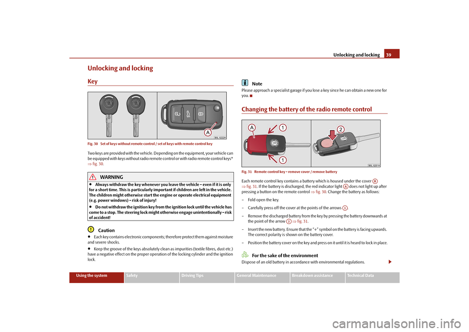
Unlocking and lockingKeyFig. 30 Set of keys without remote control / set of keys with remote control keyTwo keys are provided with the vehicle. Depending on the equipment, your vehicle can be equipped with keys without radio remote control or with radio remote control keys* ⇒ fig. 30
.WARNING
•
Always withdraw the key whenever you le
ave the vehicle - even if it is only
for a short time. This is particularly important if children are left in the vehicle. The children might otherwise start the en
gine or operate electrical equipment
(e.g. power windows) - risk of injury!•
Do not withdraw the ignition key from the ignition lock until the vehicle has
come to a stop. The steerin
g lock might otherwise enga
ge unintentionally - risk
of accident!
Caution
•
Each key contains electronic components; therefore protect them against moisture
and severe shocks.•
Keep the groove of the keys absolutely clean as impurities (textile fibres, dust etc.)
have a negative effect on the proper operation of the locking cylinder and the ignition lock.
Note
Please approach a specialist garage if you lose a key since he can obtain a new one for you.Changing the battery of the radio remote controlFig. 31 Remote control key - remove cover / remove batteryEach remote control key contains a batt
ery which is housed under the cover
⇒ fig. 31
. If the battery is discharged, the red in
dicator light does not light up after
pressing a button on the remote control
⇒fig. 30
. Change the battery as follows:
– Fold open the key. – Carefully press off the cover at the points of the arrows .– Remove the discharged battery from the key by pressing the battery downwards at
the point of the arrow
⇒fig. 31
.
– Insert the new battery. Ensure that the “+”
symbol on the battery is facing upwards.
The correct polarity is shown on the battery cover.
– Position the battery cover on the key and press on it until it is heard to lock in place.
For the sake of the environment
Dispose of an old battery in accord
ance with environmental regulations.
AB
AAA1
A2
sgg.6.book Page 39 Thursday, September 24, 2009 2:32 PM
Page 41 of 271
Unlocking and locking
40
Note
•
Pay attention to the correct pola
rity when changing the battery.
•
The replacement battery must have the same specification as the original battery.
•
If it is still not be possible to unlock or
lock the vehicle with the remote control even
after replacing the battery this means that the system has to be synchronised ⇒ page 46.Electronic immobiliserThe electronic immobiliser prevents
the vehicle being operated by an
unauthorised person.An electronic chip is integrated in the head of the key. The immobiliser is deactivated with the aid of this chip when the key is in
serted in the ignition lock. The electronic
immobiliser is automatically activated when
you withdraw the ignition key from the
lock.
Note
It is only possible to start the engine of
your car with a Genuine Škoda key with the
matching code.Child safety lockThe child safety lock prevents the re
ar door from being opened from the
inside.
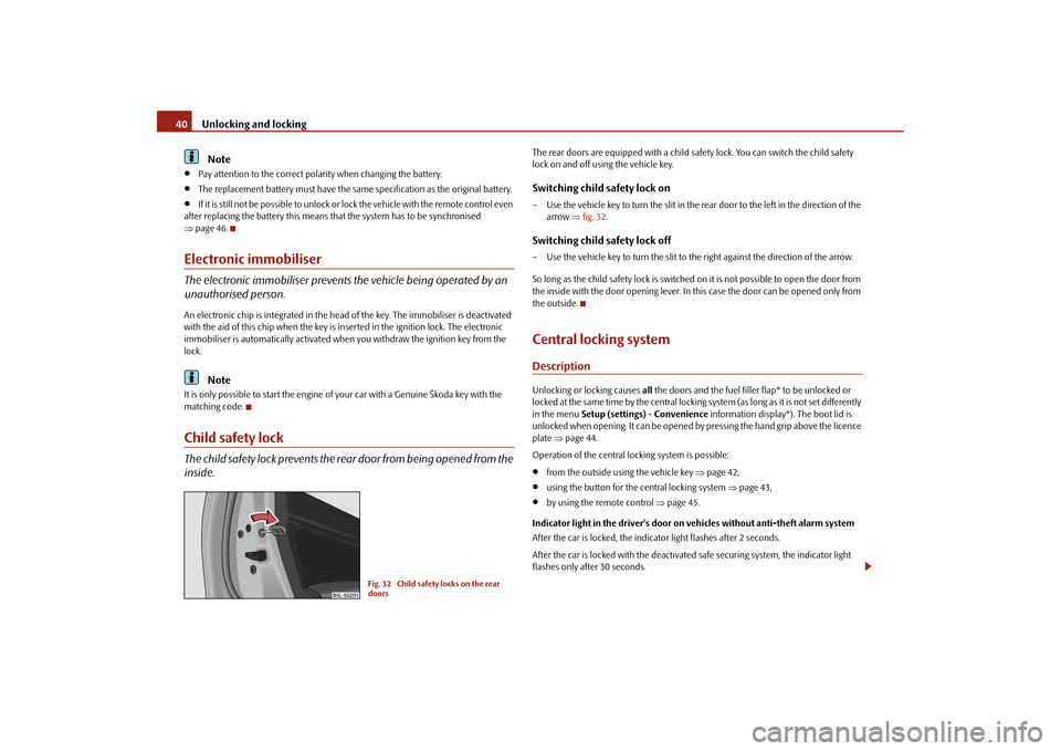
The rear doors are equipped with a child safe
ty lock. You can switch the child safety
lock on and off using the vehicle key.Switching child safety lock on– Use the vehicle key to turn the slit in the rear door to the left in the direction of the
arrow
⇒fig. 32
.
Switching child safety lock off– Use the vehicle key to turn the slit to the right against the direction of the arrow. So long as the child safety lock
is switched on it is not po
ssible to open the door from
the inside with the door opening lever. In this case the door can be opened only from the outside.Central locking systemDescriptionUnlocking or locking causes
all the doors and the fuel filler flap* to be unlocked or
locked at the same time by the central locking
system (as long as it is not set differently
in the menu
Setup (settings)
- Convenience
information display*). The boot lid is
unlocked when opening. It can be opened by pressing the hand grip above the licence plate
⇒page 44.
Operation of the central locking system is possible:•
from the outside using the vehicle key
⇒page 42,
•
using the button for the central locking system
⇒page 43,
•
by using the remote control
⇒page 45.
Indicator light in the driver's door on vehicles without anti-theft alarm system After the car is locked, the indica
tor light flashes after 2 seconds.
After the car is locked with the deactivate
d safe securing system, the indicator light
flashes only after 30 seconds.
Fig. 32 Child safety locks on the rear doors
sgg.6.book Page 40 Thursday, September 24, 2009 2:32 PM
Page 42 of 271
Unlocking and locking
41
Using the system
Safety
Driving Tips
General Maintenance
Breakdown assistance
Technical Data
Indicator light in the driv
er's door on vehicles with anti-theft alarm system
After locking the vehicle the indicator light fl
ashes for 2 seconds fast, then more slowly.
If the vehicle is locked and the safe securing system
⇒page 41 is not operating, the
indicator light in the driver door flashes for
about 2 seconds fast, goes out and starts to
flash slowly after about 30 seconds. If the indicator light first of all flashes fast for about 2 seconds, afterwards lights up for about 30 seconds and then flashes slowly, there is a fault in the system of the central locking or the interior monitor*
⇒page 47. Visit a specialist garage to obtain assist-
ance. Convenience operation of windows One can open and close the electrically powered windows when unlocking and locking the vehicle
⇒page 49.
Opening a single door* This function makes it possible to only unlock the driver's door. The other doors and the fuel filler flap* remain locked and ar
e only unlocked after repetitive unlocking.
If you wish, you can have a sp
ecialist garage activate the function of the single door
opening mode or you can activate it yourself
in the menu of the information display*
⇒ page 24. Automatic locking* All the doors and the boot lid are locked au
tomatically once the car reaches a speed of
about 15 km/h. If the ignition key is withdrawn, the car is
then automatically unlocked again. In addi-
tion, it is possible for the driver to unlock
the car by pressing the central locking button
⇒page 40 or by pulling the door opening lever.
If you wish, you can have a sp
ecialist garage activate the function of the single door
opening mode or you can activate it yourself
in the menu of the information display*
⇒ page 24.
WARNING
Locking the doors prevents
involuntary opening in an exceptional situation (an
accident). Locked doors prevent unwanted
entry into the vehicle from outside,
for example at road crossings. Locked do
ors do, however, make it more difficult
for rescuers to get into the vehicle
in an emergency - danger to life!
Note
•
In the event of an accident in which the airbags are deployed, the locked doors are
automatically unlocked in order to enable
rescuers to gain access to the vehicle.
•
Only the front doors can be unlocked and locked using the key if the central locking
system fails. You can lock or unlock ma
nually the other doors and the boot lid.
− Emergency locking of the door
⇒page 43.
− Emergency unlocking of the boot lid
⇒page 44.
Safe securingThe central locking system is equipped with a
safe securing
6) system. Locking the
vehicle from the outside causes
the door locks to be automatically blocked. It is not
possible to open the doors with the door ha
ndle either from the inside or from the
outside. This acts as
an effective deterrent for attemp
ts to break into your vehicle.
You can deactivate the safe securing sy
stem by locking twice within 2°seconds.
If the safe securing system is not operating, the warning light in the driver door flashes for about 2 seconds fast, goes out and starts to flash slowly again after about 30°seconds. The safe securing system is again activate
d the next time the vehicle is unlocked and
locked again. If the vehicle is locked and the safe securi
ng system is deactiva
ted, you can open the
vehicle from the inside by pulling on the door opening lever. The door is unlocked and opened at the same time.6)Only valid for some countries.WARNING (continued)
sgg.6.book Page 41 Thursday, September 24, 2009 2:32 PM