warning lights SKODA YETI 2012 1.G / 5L Owner's Manual
[x] Cancel search | Manufacturer: SKODA, Model Year: 2012, Model line: YETI, Model: SKODA YETI 2012 1.G / 5LPages: 225, PDF Size: 5.47 MB
Page 9 of 225
Using the system
Cockpit
Overview
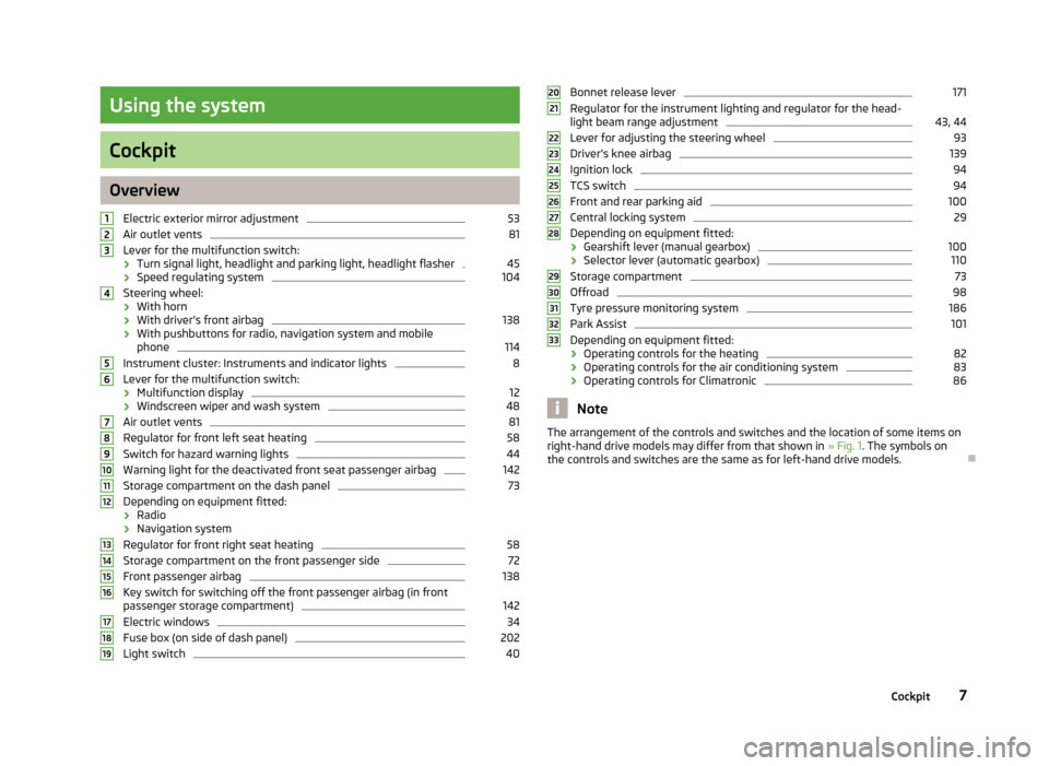
Electric exterior mirror adjustment 53
Air outlet vents 81
Lever for the multifunction switch:
› Turn signal light, headlight and parking light, headlight flasher 45
› Speed regulating system 104
Steering wheel:
› With horn
› With driver’s front airbag 138
› With pushbuttons for radio, navigation system and mobile
phone 114
Instrument cluster: Instruments and indicator lights 8
Lever for the multifunction switch:
› Multifunction display 12
› Windscreen wiper and wash system 48
Air outlet vents 81
Regulator for front left seat heating 58
Switch for hazard warning lights 44
Warning light for the deactivated front seat passenger airbag 142
Storage compartment on the dash panel 73
Depending on equipment fitted:
› Radio
› Navigation system
Regulator for front right seat heating 58
Storage compartment on the front passenger side 72
Front passenger airbag 138
Key switch for switching off the front passenger airbag (in front
passenger storage compartment) 142
Electric windows 34
Fuse box (on side of dash panel) 202
Light switch 401
2
3
4
5
6
7
8
9
10
11
12
13
14
15
16
17
18
19 Bonnet release lever 171
Regulator for the instrument lighting and regulator for the head-
light beam range adjustment 43, 44
Lever for adjusting the steering wheel 93
Driver’s knee airbag 139
Ignition lock 94
TCS switch 94
Front and rear parking aid 100
Central locking system 29
Depending on equipment fitted:
› Gearshift lever (manual gearbox) 100
› Selector lever (automatic gearbox) 110
Storage compartment 73
Offroad 98
Tyre pressure monitoring system 186
Park Assist 101
Depending on equipment fitted:
› Operating controls for the heating 82
› Operating controls for the air conditioning system 83
› Operating controls for Climatronic 86
Note
The arrangement of the controls and switches and the location of some items on
right-hand drive models may differ from that shown in »
Fig. 1. The symbols on
the controls and switches are the same as for left-hand drive models. Ð 20
21
22
23
24
25
26
27
28
29
30
31
32
33
7
Cockpit
Page 10 of 225
Instruments and Indicator Lights
Instrument Cluster
ä
Introduction
This chapter contains information on the following subjects:
Overview 8
Engine revolutions counter 9
Speedometer 9
Coolant temperature gauge 9
Fuel gauge 9
Counter for distance driven 10
Service Interval Display 10
Digital clock 11
Recommended gear 11
WARNING
■ Concentrate fully at all times on your driving! As the driver you are fully re-
sponsible for the operation of your vehicle.
■ Never operate the controls in the instrument cluster while driving, only
when the vehicle is stationary! Ð Overview
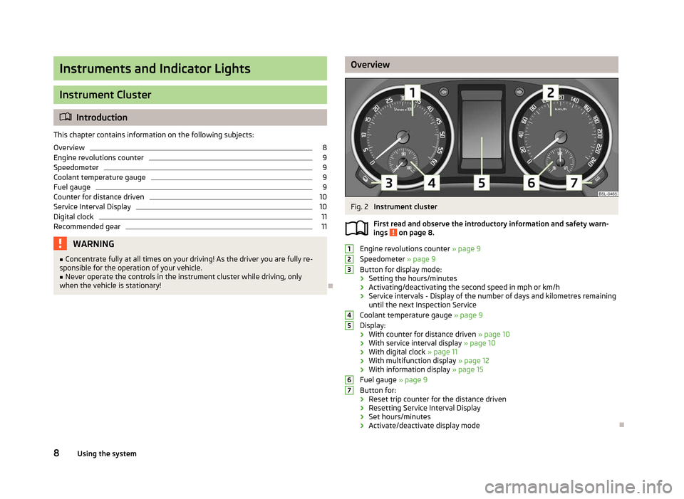
Fig. 2
Instrument cluster
First read and observe the introductory information and safety warn-
ings on page 8.
Engine revolutions counter
» page 9
Speedometer » page 9
Button for display mode:
› Setting the hours/minutes
› Activating/deactivating the second speed in mph or km/h
› Service intervals - Display of the number of days and kilometres remaining
until the next Inspection Service
Coolant temperature gauge » page 9
Display:
› With counter for distance driven
» page 10
› With service interval display
» page 10
› With digital clock
» page 11
› With multifunction display
» page 12
› With information display » page 15
Fuel gauge » page 9
Button for:
› Reset trip counter for the distance driven
› Resetting Service Interval Display
› Set hours/minutes
› Activate/deactivate display mode Ð
ä 1
2
3
4
5
6
7
8
Using the system
Page 11 of 225
Engine revolutions counter
First read and observe the introductory information and safety warn-
ings on page 8.
The red scale of the rev counter 1
» Fig. 2 on page 8 indicates the range in which
the engine control unit begins to limit the engine speed. The engine control unit
restricts the engine speed to a steady limit.
You should shift into the next higher gear before the red scale of the revolution
counter is reached, or move the selector lever into position D if your car is fitted
with an automatic gearbox.
To maintain the optimum motor speed, observe the gearshift indica-
tor » page 11. For the sake of the environment
Shifting to a higher gear in good time helps to lower fuel consumption, minimises
operating noise levels, protects the environment and contributes to a longer life
and reliability of the engine. ÐSpeedometer
First read and observe the introductory information and safety warn-
ings on page 8.
Warning against excessive speeds
An audible warning signal will sound when the vehicle speed exceeds 120 km/h.
The audible warning signal is switched off when the vehicle speed falls below
this speed limit.
Note
This function is only valid for some countries. Ð
ä
ä Coolant temperature gauge
First read and observe the introductory information and safety warn-
ings on page 8.
The coolant temperature gauge 4
» Fig. 2 on page 8 operates only when the ig-
nition is switched on.
The following guidelines regarding the temperature ranges must be observed to
avoid any damage to the engine.
Cold range
If the pointer is still in the left area of the scale it means that the engine has not
yet reached its operating temperature. Avoid high speeds, full throttle and high
engine loads.
The operating range
The engine has reached its operating temperature as soon as the pointer moves
into the mid-range of the scale, for a normal style of driving. The pointer may also
move further to the right at high engine loads and high outside temperatures. CAUTION
Additional headlights and other attached components in front of the fresh air in-
let impair the cooling efficiency of the coolant. There is then a risk of the engine
overheating at high outside temperatures and high engine loads »
page 20,
Coolant temperature/coolant level . Ð Fuel gauge
First read and observe the introductory information and safety warn-
ings on page 8.
The fuel gauge 6
» Fig. 2 on page 8 only operates when the ignition is switched
on.
The fuel tank has a capacity of about 55 litres or 60 litres 1)
. The indicator light in
the instrument cluster lights up when the pointer reaches the reserve marking .£
ä
ä
1)
Valid for Yeti 4x4.
9
Instruments and Indicator Lights
Page 13 of 225
The following will be displayed in the information display for 10
seconds:
Service in ... km or ... days.
Resetting Service Interval Display
It is only possible to reset the Service Interval Display, if a service message or at
least a pre-warning is shown in the instrument cluster display.
We recommend that this reset is completed by a
ŠKODA specialist garage.
The ŠKODA specialist garage: › Resets the memory of the display after the appropriate inspection
› Adds an entry to the Service Schedule
› Affixes the sticker with the entry of the following service interval to the side of
the dashboard on the driver's side
Reset the service interval display by using the reset button 7
»
Fig. 2 on page 8.
On vehicles which are equipped with the information display, you can reset the
Service Interval Display in the menu Settings » page 16.CAUTION
We recommend that you do not reset the Service Interval Display yourself as this
can result in the incorrect setting of the Service Interval Display, which can also
cause possible problems with the operation of your vehicle. Note
■ Never reset the display between service intervals, as this will result in the incor-
rect display. ■ Information is retained in the Service Interval Display even after the vehicle bat-
tery is disconnected.
■ If the instrument cluster is exchanged after a repair, the correct values must be
entered in the counter for the Service Interval Display. This work is carried out by
a ŠKODA specialist garage. ■ After resetting the display with flexible service intervals, the displayed data is
the same as that for a vehicle with fixed service intervals. We therefore recom-
mend that the Service Interval Display is only reset by a
ŠKODA Service Partner,
who will reset the display with a vehicle system tester. ■ For more information on the service intervals » Service Plan. Ð Digital clock
First read and observe the introductory information and safety warn-
ings on page 8.
The clock is set with the buttons 3
and 7
» Fig. 2 on page 8.
Select the display that you wish to change with the button 3
and carry out the
change with the button 7
.
On vehicles that are fitted with the information display, it is also possible to set
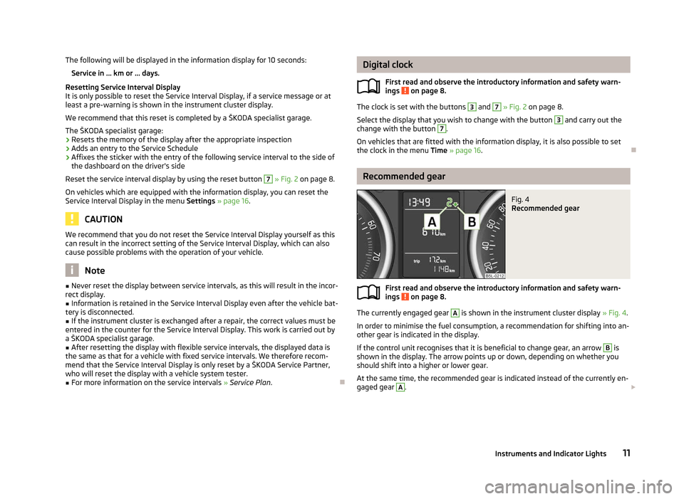
the clock in the menu Time » page 16. Ð Recommended gear
Fig. 4
Recommended gear
First read and observe the introductory information and safety warn-
ings on page 8.
The currently engaged gear A
is shown in the instrument cluster display
» Fig. 4.
In order to minimise the fuel consumption, a recommendation for shifting into an-
other gear is indicated in the display.
If the control unit recognises that it is beneficial to change gear, an arrow B
is
shown in the display. The arrow points up or down, depending on whether you
should shift into a higher or lower gear.
At the same time, the recommended gear is indicated instead of the currently en-
gaged gear A
.
£
ä
ä
11
Instruments and Indicator Lights
Page 15 of 225
Total-trip memory (memory 2)
The total-trip memory gathers data from any number of individual journeys up to
a total of 19
hours and 59 minutes driving or 1 999 kilometres driven, and on vehi-
cles which are fitted with an information display up to a total of 99 hours and
59 minutes driving or 9 999 kilometres driven. The memory is deleted when ei-
ther of these limits is reached and the calculation starts all over again.
Unlike the single-trip memory, the total-trip memory is not deleted after a period
of interruption of driving of 2 hours. Note
All information in the memory 1 and 2 is erased if the battery of the vehicle is dis-
connected. ÐOperation
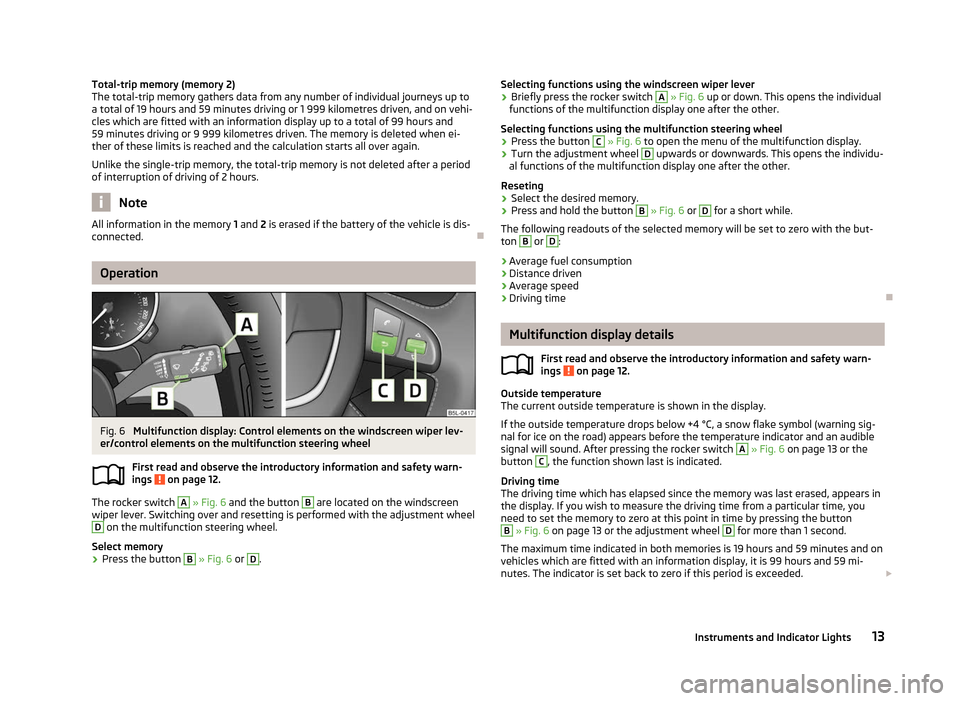
Fig. 6
Multifunction display: Control elements on the windscreen wiper lev-
er/control elements on the multifunction steering wheel
First read and observe the introductory information and safety warn-
ings on page 12.
The rocker switch A
» Fig. 6
and the button B
are located on the windscreen
wiper lever. Switching over and resetting is performed with the adjustment wheel D
on the multifunction steering wheel.
Select memory
› Press the button B
» Fig. 6 or D
.
ä Selecting functions using the windscreen wiper lever
› Briefly press the rocker switch A
» Fig. 6
up or down. This opens the individual
functions of the multifunction display one after the other.
Selecting functions using the multifunction steering wheel
› Press the button C
» Fig. 6 to open the menu of the multifunction display.
› Turn the adjustment wheel D
upwards or downwards. This opens the individu-
al functions of the multifunction display one after the other.
Reseting
› Select the desired memory.
› Press and hold the button B
» Fig. 6 or D
for a short while.
The following readouts of the selected memory will be set to zero with the but-
ton B
or D
:
› Average fuel consumption
› Distance driven
› Average speed
› Driving time Ð Multifunction display details
First read and observe the introductory information and safety warn-
ings on page 12.
Outside temperature
The current outside temperature is shown in the display.
If the outside temperature drops below +4
°C, a snow flake symbol (warning sig-
nal for ice on the road) appears before the temperature indicator and an audible
signal will sound. After pressing the rocker switch A
» Fig. 6 on page 13 or the
button C
, the function shown last is indicated.
Driving time
The driving time which has elapsed since the memory was last erased, appears in
the display. If you wish to measure the driving time from a particular time, you
need to set the memory to zero at this point in time by pressing the button B
» Fig. 6 on page 13 or the adjustment wheel D
for more than 1 second.
The maximum time indicated in both memories is 19 hours and 59
minutes and on
vehicles which are fitted with an information display, it is 99 hours and 59 mi-
nutes. The indicator is set back to zero if this period is exceeded. £
ä
13
Instruments and Indicator Lights
Page 17 of 225
Adjusting the speed limit while the vehicle is moving
›
With the button A
» Fig. 6
on page 13 or the adjustment wheel D
, select the
menu item Warning against excessive speeds .
› Drive at the desired speed, e.g. 50 km/h.
› Press the button B
or the adjustment wheel D
to accept the current speed as
the speed limit (the value flashes).
If you wish to change the set speed limit, it is changed in 5
km/h intervals (e.g. the
accepted speed of 47 km/h increases to 50 km/h or decreases to 45 km/h).
› Press again the button B
or the adjustment wheel D
to confirm the speed
limit, or wait approx. 5 seconds and the setting is saved automatically (the value
stops flashing).
Change or delete speed limit
› With the button A
» Fig. 6
on page
13 or the adjustment wheel D
, select the
menu item Warning against excessive speeds .
› Pressing the button B
or the adjustment wheel D
deletes the speed limit.
› Pressing the button B
or the adjustment wheel D
again activates change
mode for the speed limit.
If the set speed limit is exceeded, an audible signal will sound as a warning. At
the same time the message Warning against excessive speeds appears on the
display with the set limit value.
The set speed limit value remains stored even after switching off the ignition. ÐMAXI DOT (information display)
ä
Introduction
This chapter contains information on the following subjects:
Main menu 15
Settings 16
Door, boot lid and bonnet warning 17
Auto Check Control 17
The information display provides you with information on the current operating
state of your vehicle . The information system also provides you with data (de-
pending on the equipment installed in the vehicle) relating to the radio, mobile
phone, multi-functional indicator, navigation system, the unit connected to the
MDI input and the automatic gearbox » page 109. WARNING
Concentrate fully at all times on your driving! As the driver you are fully re-
sponsible for the operation of your vehicle. CAUTION
Pull out the ignition key if coming in contact with the display (e.g. when cleaning)
to prevent any possible damage. Ð Main menu
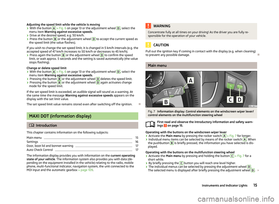
Fig. 7
Information display: Control elements on the windscreen wiper lever/
control elements on the multifunction steering wheel
First read and observe the introductory information and safety warn-
ings on page 15.
Operating with the buttons on the windscreen wiper lever
›
Activate the Main menu
by pressing the rocker switch A
» Fig. 7 for longer.
› Individual menu items can be selected by means of the rocker switch A
. When
the pushbutton B
is briefly pressed, the information you have selected is dis-
played.
Operating with the buttons on the multifunction steering wheel
› Activate the Main menu
by pressing and holding the button C
» Fig. 7
for a
short while.
› By briefly pressing the C
button you will reach one level higher.
› The individual menus can be selected by pressing the adjustment wheel D
.
The selected menu is displayed after briefly pressing the adjustment wheel D
.
£
ä
15
Instruments and Indicator Lights
Page 18 of 225
The following information can be selected (depending on the equipment installed
on the vehicle):
■ MFD » page 12
■ Audio » Operating instructions for the radio
■ Navigation » Operating instructions for the navigation system
■ Phone »
page 114
■ Aux. Heating » page 88
■ Assistants » page 41 » page 107
■ Vehicle status » page 17
■ Settings » page 16
The menu items Audio and Navigation are only displayed when the factory-fitted
radio or navigation system is switched on.
The menu item Aux. heating is only displayed if a factory-fitted auxiliary heating
is installed.
The menu item Assistants is only displayed if the vehicle is fitted with cornering
lights or with fatigue detection. Note
■ If warning messages are shown in the information display, these messages
must be confirmed with the button B
on the windscreen wiper lever or with the
adjustment wheel D
on the multifunction steering wheel to call up the main
menu.
■ If the information display is not activated at that moment, the menu always
shifts to one of the higher levels after approx. 10
seconds.
■ The operation of the factory-fitted radio or navigation system is described in
separate operating instructions to be found in the on-board literature. ÐSettings
First read and observe the introductory information and safety warn-
ings on page 15.
You can change certain settings by means of the information display. The current
setting is shown on the information display in the respective menu at the top be-
low the line.
ä The following information can be selected (depending on the equipment installed
on the vehicle):
■ Language
■ MFD Data
■ Convenience
■ Lights & Vision
■ Time
■ Winter tyres
■ Units
■ Assistants
■ Alternative speed displayed
■ Service
■ Factory setting
■ Back
Select the menu item Back to return to one level higher in the menu.
Language
You can set the language for the warning and information texts here.
MFD displays
Activate or deactivate certain displays of the multifunction display here.
Comfort
This is where the following functions can be activated, deactivated or adjusted:
Rain closing Switch on/off the function for automatically closing the
window and panoramic tilt/slide sunroof in a locked ve-
hicle when it starts raining
a)
. If the function is set and it
is not raining, the windows including the panoramic tilt/
slide sunroof will close automatically after approx.
12 hours.
Central locking Switch on/off the central locking and automatic locking
function.
ATA confirm Switch on/off the audible signal indicating activation of
the anti-theft alarm system.
Window op. Only convenience mode for the driver window or for all
of the windows can be adjusted here.
Mirror down Switch on/off the function for mirror lowering on the
front passenger side when engaging the reverse gear b)
. £ 16
Using the system
Page 19 of 225
Mirror adjust.
Switch on/off the function for left and right exterior
mirror setting simultaneously.
Factory setting Restore the Convenience factory setting.a)
This function is only available on vehicles with a rain sensor.
b) This function is only available on vehicles with an electrically adjustable driver seat.
Lights and visibility
This is where the following functions can be activated, deactivated or adjusted:
Coming Home Switch on/off and adjust the light duration of the Com-
ing Home function.
Leaving Home Switch on/off and adjust the light duration of the Com-
ing Home function.
Dayl. dri. light Switch on/off the “DAY LIGHT” function.
Rear wiper Switch on/off the function for automatic rear window
wiping.
Lane ch. flash Switch on/off the convenience flashing function.
Travel mode Switch on/off the travel model function.
Factory setting Restore the factory setting for the lighting.Time
The time, time format (12 or 24 hour indicator) and the changeover between sum-
mer/winter time can be set here.
Winter tyres
Here, you can set the speed at which an audible signal should sound. This func-
tion is, for example, used for winter tyres where the maximum permissible speed
is lower than the maximum speed of the vehicle.
When exceeding the speed, the following is shown on the information display:
Winter tyres:
max. speed ... km/h
Units of measurement
The units for the temperature, consumption and distance driven can be set here.
Assistants
The tones of the audible signals for the parking aid can be adjusted here. Second speed
The display of the second speed in mph or in km/h can be switched on here.
Service
Here you can have the remaining kilometres and days until the next service inter-
val displayed, and reset the Service Interval Display.
Factory setting
After selecting the menu Factory setting
the factory setting of the information
display is restored. Ð Door, boot lid and bonnet warning
First read and observe the introductory information and safety warn-
ings on page 15.
If at least one door is open, or the boot or bonnet is open, the information display
indicates the relevant
open door or boot/bonnet.
An audible signal also sounds if the vehicle is travelling at more than 6
km/h.Ð Auto Check Control
First read and observe the introductory information and safety warn-
ings on page 15.
Vehicle condition
Certain functions and conditions of individual vehicle systems are checked contin-
uously when the ignition is switched on and also while driving.
Some error messages and other information are displayed in the information dis-
play. The messages are displayed at the same time as the symbols in the informa-
tion display or the indicator lights in the instrument cluster » page 18.
If there is at least one error message, the menu item Vehicle status is displayed
in the menu. After selecting this menu the first of the error messages is dis-
played. Several error messages are shown on the display under the message e.g.
1/3. This indicates that the first of a total of three error messages is being dis-
played. £
ä
ä
17
Instruments and Indicator Lights
Page 20 of 225
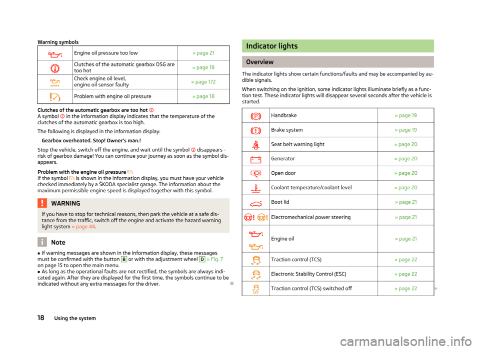
Warning symbols
Engine oil pressure too low
» page 21
Clutches of the automatic gearbox DSG are
too hot » page 18
Check engine oil level,
engine oil sensor faulty
» page 172
Problem with engine oil pressure
» page 18Clutches of the automatic gearbox are too hot
A symbol in the information display indicates that the temperature of the
clutches of the automatic gearbox is too high.
The following is displayed in the information display: Gearbox overheated. Stop! Owner's man.!
Stop the vehicle, switch off the engine, and wait until the symbol disappears -
risk of gearbox damage! You can continue your journey as soon as the symbol dis-
appears.
Problem with the engine oil pressure
If the symbol is shown in the information display, you must have your vehicle
checked immediately by a
ŠKODA specialist garage. The information about the
maximum permissible engine speed is displayed together with this symbol. WARNING
If you have to stop for technical reasons, then park the vehicle at a safe dis-
tance from the traffic, switch off the engine and activate the hazard warning
light system » page 44. Note
■ If warning messages are shown in the information display, these messages
must be confirmed with the button B
or with the adjustment wheel D
» Fig. 7
on page 15 to open the main menu. ■ As long as the operational faults are not rectified, the symbols are always indi-
cated again. After they are displayed for the first time, the symbols continue to be
indicated without any extra messages for the driver. Ð Indicator lights
Overview
The indicator lights show certain functions/faults and may be accompanied by au-
dible signals.
When switching on the ignition, some indicator lights illuminate briefly as a func-
tion test. These indicator lights will disappear several seconds after the vehicle is
started.
Handbrake
» page 19
Brake system
» page 19
Seat belt warning light
» page 20
Generator
» page 20
Open door
» page 20
Coolant temperature/coolant level
» page 20
Boot lid
» page 21
Electromechanical power steering
» page 21
Engine oil
» page 21
Traction control (TCS)
» page 22
Electronic Stability Control (ESC)
» page 22
Traction control (TCS) switched off
» page 22£18
Using the system
Page 21 of 225
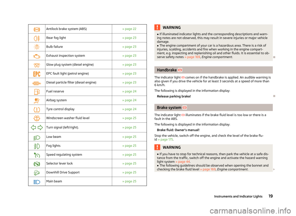
Antilock brake system (ABS)
» page 22
Rear fog light
» page 23
Bulb failure
» page 23
Exhaust inspection system
» page 23
Glow plug system (diesel engine)
» page 23
EPC fault light (petrol engine)
» page 23
Diesel particle filter (diesel engine)
» page 23
Fuel reserve
» page 24
Airbag system
» page 24
Tyre control display
» page 24
Windscreen washer fluid level
» page 25
Turn signal (left/right).
» page 25
Low beam
» page 25
Fog lights
» page 25
Speed regulating system
» page 25
Selector lever lock
» page 25
Downhill Drive Support
» page 25
Main beam
» page 25 WARNING
■ If illuminated indicator lights and the corresponding descriptions and warn-
ing notes are not observed, this may result in severe injuries or major vehicle
damage.
■ The engine compartment of your car is a hazardous area. There is a risk of
injuries, scalding, accidents and fire when working in the engine compart-
ment, e.g. inspecting and replenishing oil and other fluids. It is essential to ob-
serve safety notes »
page 169, Engine compartment . Ð Handbrake
The indicator light
comes on if the handbrake is applied. An audible warning is
also given if you drive the vehicle for at least 3 seconds at a speed of more than
6 km/h.
The following is displayed in the information display:
Release parking brake! Ð Brake system
The indicator light illuminates if the brake fluid level is too low or there is a
fault in the ABS.
The following is displayed in the information display:
Brake fluid: Owner's manual!
Stop the vehicle, switch off the engine, and check the level of the brake flu-
id » page 175. WARNING
■ If you have to stop for technical reasons, then park the vehicle at a safe dis-
tance from the traffic, switch off the engine and activate the hazard warning
light system » page 44.
■ The following guidelines should be observed when opening the bonnet and
checking the brake fluid level » page 169, Engine compartment .£
19
Instruments and Indicator Lights