trailer SKODA YETI 2013 1.G / 5L User Guide
[x] Cancel search | Manufacturer: SKODA, Model Year: 2013, Model line: YETI, Model: SKODA YETI 2013 1.G / 5LPages: 266, PDF Size: 26.71 MB
Page 152 of 266
Briefly push the rocker button B into the RES/+ position in order to resume the
stored speed after the clutch or brake pedal is released.
START-STOP
Introduction
This chapter contains information on the following subjects:
Starting/shutting down the engine
149
Operating conditions of the system
150
Manually activating/deactivating the system
150
Information messages
151
The START-STOP system helps you to save fuel while at the same time reducing
harmful exhaust emissions and CO 2 emissions.
The function is automatically activated each time the ignition is switched on. In the start-stop mode, the engine automatically switches to the vehicle's idle phase, e.g. when stopped at traffic lights. The engine restarts automatically
where necessary.
The system can work only if the following basic conditions are met. The driver's door is closed.
The driver has fastened the seat belt.
The bonnet is closed.The driving speed was higher than 4 km.h after the last stop.
No trailer is coupled.
WARNING■ The brake servo unit and power steering only operate if the engine is run-
ning.■
Never let the vehicle roll with the engine switched off.
CAUTION
Always deactivate the START-STOP system before driving through wa-
ter » page 134 .Note■
If the driver's seat belt is removed for more than approx. 30 seconds or the driv-
er's door is opened during stop mode on vehicles with manual transmission or au- tomatic transmission (when the selector lever in position P), the engine must be
started manually » page 120.■
After manually starting the engine on vehicles with manual transmission, auto-
matic engine shut down is not possible until the vehicle has travelled the re-
quired minimum distance for START-STOPP mode.
■
If, on vehicles with automatic transmission, the selector lever positions D, S or N
are selected after driving in reverse, the vehicle will first need to achieve a speed
of over 10 km/h before automatic engine shut down can take place again.
■
Changes to the outdoor temperature can have an effect on the internal temper-
ature of the vehicle battery even after several hours. If the vehicle remains out- doors for a long time in minus temperatures or in direct sunlight, it can take sev-
eral hours until the internal temperature of the vehicle battery reaches a suitable
temperature for proper operation of the START STOP system.
■
If the Climatronic is running in automatic mode, it is possible that under certain
conditions the engine may not switch off automatically.
Starting/shutting down the engine
First read and observe the introductory information and safety warn-ings
on page 149.
Vehicles with manual transmission
›
Stop the vehicle (where necessary, apply the handbrake).
›
Put the gear stick into Neutral.
›
Release the clutch pedal.
Automatic engine shut down (STOP phase) takes place. The warning symbol
appears in the instrument cluster display.
›
Depress the clutch pedal.
The automatic start procedure takes place again (START phase). The warning
symbol
goes out.
Vehicles with automatic transmission
›
Bring the vehicle to a stop and depress the brake pedal.
Automatic engine shut down takes place. The warning symbol
appears in the
instrument cluster display.
›
Release the brake pedal.
149Assist systems
Page 155 of 266
Towing a trailer
Towing device
Introduction
This chapter contains information on the following subjects:
Description
152
Setting the ready position
153
Installing the ball rod
154
Check proper fitting
155
Removing the ball rod
155
Use and care
156
If your vehicle has already been factory-fitted with a towing device or is fitted
with a towing device from ŠKODA Original Accessories, then it meets all of the
technical requirements and national legal regulations for towing a trailer.
Your vehicle is fitted with a 13-pin power socket for the electrical connection be-
tween the vehicle and trailer. If the trailer that is to be towed has a 7-pin connec-
tor , you can use a suitable adapter from ŠKODA Original Accessories.
The maximum trailer nose weight is 80 kg and 85 kg 1)
.
WARNING■ Check that the tow bar is seated correctly and is secured in the mounting
recess before the start of every journey.■
Do not use the tow bar if it is not correctly inserted and secured in the
mounting recess.
■
Do not use the towing device if it is damaged or if there are parts missing.
■
Do not modify or adapt the towing device in any way.
■
Never release the tow bar while the trailer is still coupled.
CAUTIONTake care when handling the tow bar so as to avoid damaging the paintwork on
the bumper.
Description
Fig. 126
Carrier for the towing device/tow bar
First read and observe the introductory information and safety warn-
ings
on page 152.
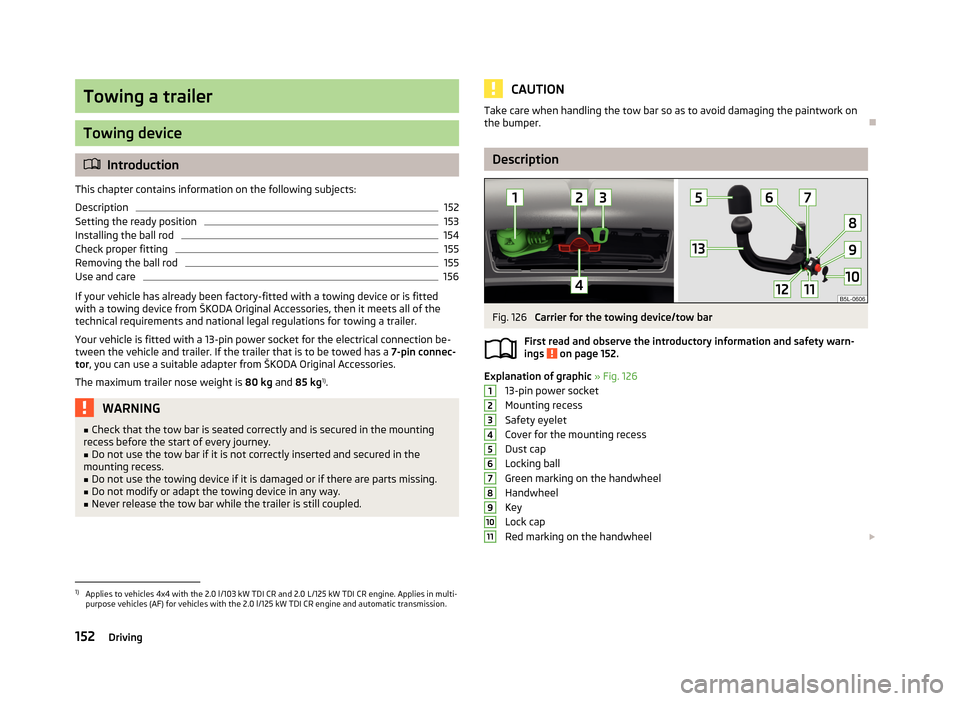
Explanation of graphic » Fig. 126
13-pin power socket
Mounting recess
Safety eyelet
Cover for the mounting recess
Dust cap
Locking ball
Green marking on the handwheel
Handwheel
Key
Lock cap
Red marking on the handwheel
12345678910111)
Applies to vehicles 4x4 with the 2.0 l/103 kW TDI CR and 2.0 L/125 kW TDI CR engine. Applies in multi-
purpose vehicles (AF) for vehicles with the 2.0 l/125 kW TDI CR engine and automatic transmission.
152Driving
Page 156 of 266
Green box on the tow bar
Tow ball
The tow bar can be removed and is kept in the spare wheel compartment or in a
compartment for the spare wheel in the boot » page 220, Vehicle tool kit .
Note
On the bottom of the key is a code number. If you lose a key, please contact a
specialist garage, who will be able to use this code number to provide you with a new one.
Setting the ready position
Fig. 127
Setting the ready position
Fig. 128
Ready position
1213First read and observe the introductory information and safety warn-
ings on page 152.
Always set the ready position before fitting the tow bar.
›
Turn the key
A
in direction of the arrow
1
to the stop » Fig. 127.
›
Hold the tow bar with your left hand.
›
Using your right hand, pull the handwheel
B
in the direction of the arrow
2
and drag in the direction of the arrow
3
to the stop.
The handwheel remains locked in this position.
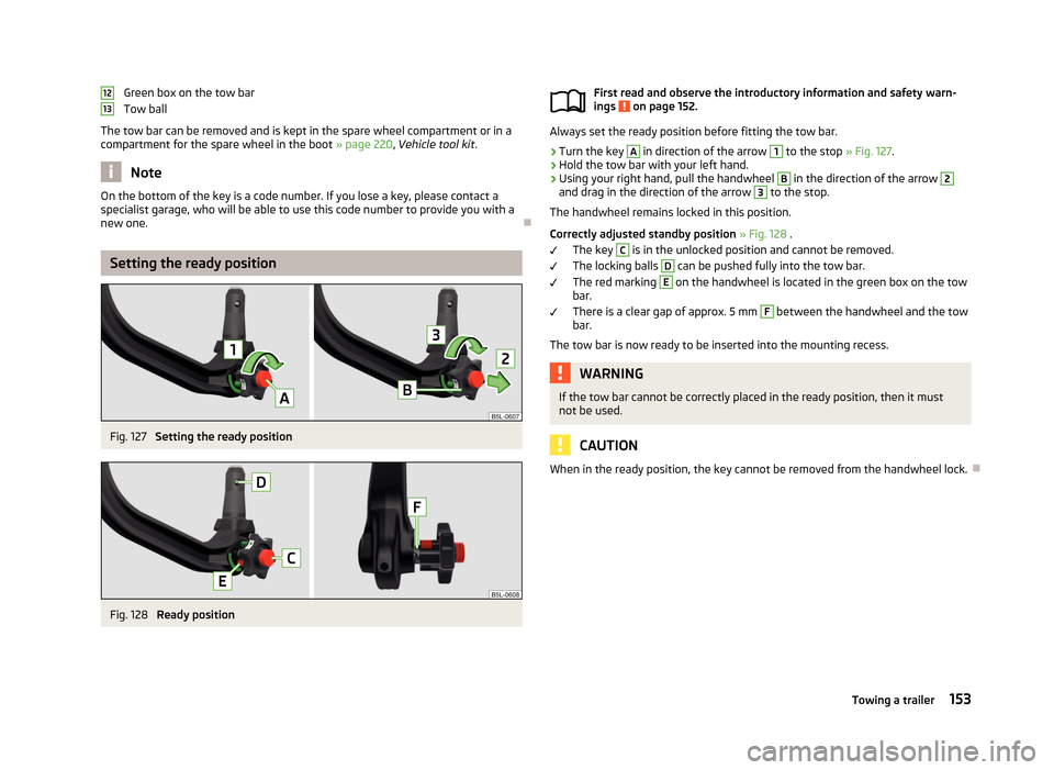
Correctly adjusted standby position » Fig. 128 .
The key
C
is in the unlocked position and cannot be removed.
The locking balls
D
can be pushed fully into the tow bar.
The red marking
E
on the handwheel is located in the green box on the tow
bar.
There is a clear gap of approx. 5 mm
F
between the handwheel and the tow
bar.
The tow bar is now ready to be inserted into the mounting recess.
WARNINGIf the tow bar cannot be correctly placed in the ready position, then it must
not be used.
CAUTION
When in the ready position, the key cannot be removed from the handwheel lock.
153Towing a trailer
Page 158 of 266
Check proper fittingFig. 131
Check that the tow bar is attach-
ed properly
First read and observe the introductory information and safety warn-
ings on page 152.
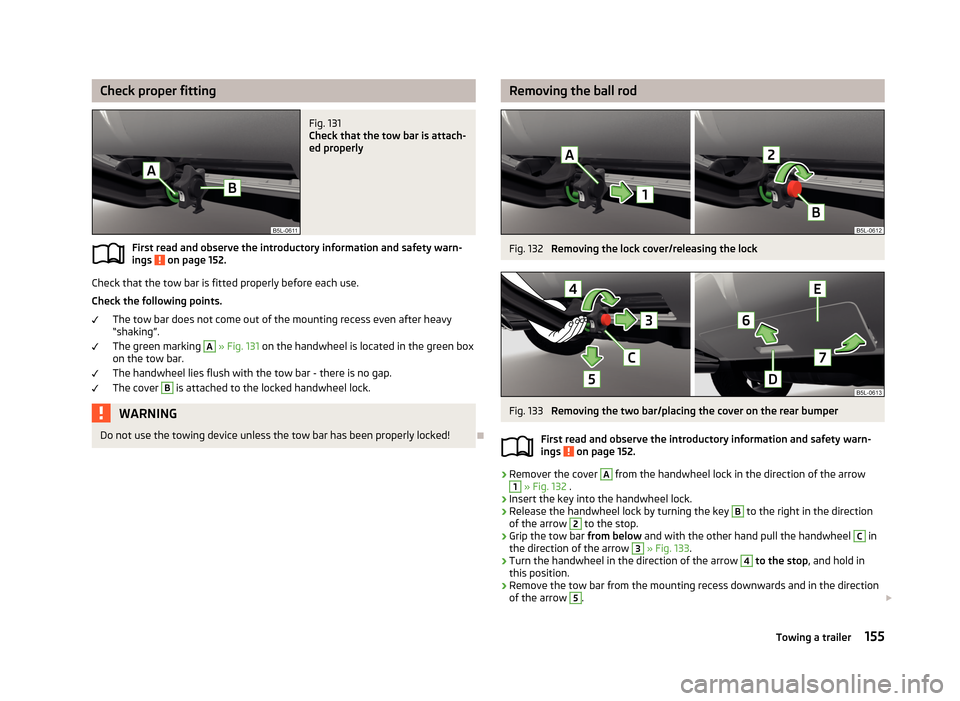
Check that the tow bar is fitted properly before each use.
Check the following points. The tow bar does not come out of the mounting recess even after heavy
“shaking”.
The green marking
A
» Fig. 131 on the handwheel is located in the green box
on the tow bar.
The handwheel lies flush with the tow bar - there is no gap. The cover
B
is attached to the locked handwheel lock.
WARNINGDo not use the towing device unless the tow bar has been properly locked!
Removing the ball rodFig. 132
Removing the lock cover/releasing the lock
Fig. 133
Removing the two bar/placing the cover on the rear bumper
First read and observe the introductory information and safety warn-
ings
on page 152.
›
Remover the cover
A
from the handwheel lock in the direction of the arrow
1
» Fig. 132 .
›
Insert the key into the handwheel lock.
›
Release the handwheel lock by turning the key
B
to the right in the direction
of the arrow
2
to the stop.
›
Grip the tow bar from below and with the other hand pull the handwheel
C
in
the direction of the arrow
3
» Fig. 133 .
›
Turn the handwheel in the direction of the arrow
4
to the stop , and hold in
this position.
›
Remove the tow bar from the mounting recess downwards and in the direction
of the arrow
5
.
155Towing a trailer
Page 159 of 266
At the same time, the tow bar latches into the ready position and is therefore
ready to be re-inserted into the mounting recess » .›
Attach the cover for the mounting recess
4
» Fig. 126 on page 152 » .
›
Grip the cover on the rear bumper
E
» Fig. 133 at the handle
D
and position in
the direction of the arrow
6
on the checkmark underneath the upper edge of
the bumper.
›
Push this cover onto the lower edge and onto the two sides in the direction of the arrow
7
.
WARNING■ Never allow the tow bar to remain unsecured in the boot. This could cause
damage on sudden braking, and could put the safety of the occupants at risk.■
Never remove the tow bar while the trailer is still coupled.
CAUTION
■ If the handwheel is not turned all the way to the stop, then it will return to its
initial position when the tow bar is removed, and will rest on the tow bar and not
engage into the ready position. The tow bar will then need to be brought into this position before the next time it is fitted.■
The mounting recess must be closed with the cover following removal. This pre-
vents foreign bodies from getting into the mounting recess.
■
Clean any dirt from the tow bar before stowing it away in the box with the vehi-
cle tool kit.
Note
We recommend putting the protective cover onto the ball head before removing
the tow bar.
Use and care
First read and observe the introductory information and safety warn-
ings
on page 152.
Close the mounting recess with the cover to prevent any dirt from getting in.
Always check the tow bar before hitching a trailer. Apply suitable grease where
necessary.
Use the protective cover when stowing away the tow bar, in order to stop the boot from getting dirty.
In the event of dirt, clean the surfaces of the mounting recess and treat with a
suitable preservative.
CAUTION
Apply grease to the upper part of the mounting recess. Make sure you do not re-
move any grease.
Trailer
Introduction
This chapter contains information on the following subjects:
Loading a trailer
156
Driving with a trailer
157
Trailer stabilisation (TSA)
158
Anti-theft alarm system
159WARNINGAlways drive particularly carefully with the trailer.
Loading a trailer
First read and observe the introductory information and safety warn-
ings
on page 156.
The vehicle/trailer combination must be balanced, whereby the maximum permis-
sible drawbar load must be utilised. If the drawbar load is too low, it jeopardises
the performance of the vehicle/trailer combination.
Distribution of the load
Distribute the load in the trailer in such a way that heavy items are located as close to the axle as possible. Secure the items from slipping.
156Driving
Page 160 of 266
The distribution of the weight is very poor if your vehicle is unladen and the trail-
er is laden. Maintain a particularly low speed if you cannot avoid driving with this
combination.
Tyre pressure
Correct the tyre inflation pressure on your vehicle for a “full load” » page 213,
Service life of tyres .
Towing capacity and trailer weight
The permissible trailer load must not be exceeded under any circumstan- ces » page 244 , Technical data .
The trailer loads specified apply only to altitudes up to 1,000 metres above mean sea level.
The engine output falls as altitude increases, as does the vehicle's climbing pow- er. Therefore, for every additional 1000 m in height (or part), the maximum per-
missible towed weight must be reduced by 10%.
The towed weight is made up of the actual weights of the loaded towing vehicle
and the loaded trailer.
The trailer and drawbar load information on the type plate of the towing device is merely a test value for the towing device. The vehicle-specific values are detailed in the vehicle documents.WARNING■ Do not exceed the maximum permissible axle and drawbar load and the
maximum permissible total or towed weight of the vehicle and the trailer –
risk of accident and serious injury.■
Slipping loads can significantly impair the stability and safety of the vehicle/
trailer combination – risk of accident and serious injury.
Driving with a trailerFig. 134
Swivel out the 13-pin power
socket
First read and observe the introductory information and safety warn-
ings on page 156.
Before the journey
›
Swing the 13-pin socket in the direction of arrow
A
» Fig. 134 .
›
Lift off protective cap
5
» Fig. 126 on page 152.
After the journey
›
Swivel the 13-pin power socket
A
» Fig. 134 back in in the opposite direction to
the arrow.
›
Place the protective cover
5
» Fig. 126 on page 152 onto the tow bar.
Safety eyelet
The purpose of the safety eyelet
B
» Fig. 134 is to attach the breakaway cable of
the trailer.
When attaching the breakaway cable to the safety eye, it must sag freely in all
trailer positions in relation to the vehicle (sharp bends, in reverse, etc.)
Exterior mirrors
You have to have additional exterior mirrors fitted if you are not able to see the
traffic behind the trailer with the standard rear-view mirrors. The national legal
requirements must be observed.
Headlights
The front of the vehicle may lift up when a trailer is being towed and the head-
lights may dazzle other road users.
157Towing a trailer
Page 161 of 266
Adjust the headlights using the headlight beam control » page 48, Headlight
beam control 1)
.
Driving speed
For safety reasons, do not drive faster than 80 km/h when towing a trailer.
Immediately reduce your speed as soon as even the slightest swaying of the trail-
er is detected. Never attempt to stop the trailer from “swaying” by accelerating.
Brakes
Apply the brakes in good time! If the trailer is fitted with a trailer brake, apply the
brakes gently at first, then brake firmly. This will avoid brake jolts resulting from
the trailer wheels locking.
On downhill sections shift down a gear in good time to also use the engine as a
brake.
Engine overheating
If the needle for the coolant temperature gauge moves into the right-hand area
or the red area of the scale, the speed must be reduced immediately.
Stop and switch off the engine if the indicator light
in the instrument cluster
starts to flash. Wait a few minutes and check the level of coolant » page 205,
Checking the coolant level .
The following guidelines must be observed » page 16,
Coolant .
The coolant temperature can be reduced by switching on the heating.WARNING■ Never use the safety eyelet for towing!■Adapt your speed to the conditions of the road surface and to the traffic sit-
uation.■
Improper or incorrectly connected electric cables can energise the trailer and
cause functional faults to the vehicle's entire electrical system as well as acci-
dents and severe injuries.
■
Work on the electrical system must only be carried out by specialist garages.
■
Never directly connect the trailer's electrical system with the electrical con-
nections for the tail lights or other current sources.
Note■ After coupling the trailer and connecting the power socket, check that the rear
lights on the trailer are working correctly.■
If there is an error in the trailer lighting, check the fuses in the fuse box in the
dash panel » page 236.
■
Contact between the breakaway cable and the safety eyelet can result in me-
chanical wear on the surface protection of the eyelet. Such wear does not impair
the functioning of the safety eyelet and does not constitute a fault. It is excluded from the warranty coverage.
■
If you tow a trailer frequently, you should also have your vehicle inspected be-
tween service intervals.
■
The handbrake on the towing vehicle must be applied when coupling and un-
coupling the trailer.
Trailer stabilisation (TSA)
First read and observe the introductory information and safety warn-
ings
on page 156.
The trailer stabilisation is an extension of the stabilisation control that works in
conjunction with the counter-steering assistance to reduce the amount the trail-
er "sways".
After turning on the ignition, the ESC indicator light
in the instrument cluster
lights up for about 2 seconds longer than the ABS indicator light.
Function requirements for trailer stabilisation. The trailer was shipped from the factory or purchased from the ŠKODA genu-
ine accessories range.
The ESC system is active (in the instrument cluster, the warning lights illumi-
nates
or
) » page 18 does not .
The trailer is electrically connected to the towing vehicle via the trailer sock-
et.
The speed is higher than approx. 60 km/h.
The trailer has a rigid drawbar.
1)
Applies to vehicles with bi-xenon headlights.
158Driving
Page 162 of 266
WARNINGThe increased safety offered by the trailer stabilisation must not tempt you to
take greater risks than otherwise.
CAUTION
■ The trailer stabilisation need not be able to correctly detect all of driving situa-
tions.■
Trailers that sway slightly may not always be detected by the trailer stabilisa-
tion and are thus not stabilised accordingly.
■
Release the pressure on the accelerator pedal if the system is being regulated.
■
Avoid abrupt and sudden driving/braking manoeuvres.
Note
The trailer stabilisation works for both braked and unbraked trailers.
Anti-theft alarm system
First read and observe the introductory information and safety warn-
ings
on page 156.
If the vehicle is locked, the alarm is activated when the electrical connection to
the trailer is interrupted.
Always switch off the anti-theft alarm system before a trailer is coupled or uncou- pled » page 39 .
Conditions for including a trailer in the anti-theft alarm system. The vehicle is factory-fitted with an anti-theft alarm system and towing de-
vice.
The trailer is electrically connected to the towing vehicle via the trailer sock-
et.
The electrical system of the vehicle and trailer is functional.
The vehicle is locked with the vehicle key and the anti-theft alarm system is
activated.
Note
For technical reasons, trailers with rear LED lights cannot be connected to the an-
ti-theft alarm system.
159Towing a trailer
Page 185 of 266
General Maintenance
Vehicle care
Service intervals
Introduction
This chapter contains information on the following subjects:
Overview of service intervals
182
Fixed service intervals QI1 - QI4
183
Variable service interval QI6
183
Information about the ŠKODA service
183
The service interval display in the instrument cluster will remind you to carry out
every service stipulated by the manufacturer at the right time in order to prevent you from forgetting any.
Timely and proper performance of servicing works is one of the requirements for the settlement of potential warranty claims.
The completion of services can be verified by the validated service certificate andthe corresponding receipts.
The specified service intervals are tailored to normal operating conditions.
In the case of difficult operating conditions, it is necessary to have some service
work performed before the date of the next service or between the specified
service intervals. This applies mainly to the cleaning or the replacement of the air
filter insert in regions with heavy dust pollution as well as checking and replacing
the toothed belt, but also to vehicles with diesel particle filters, which can put
greater strain on the engine oil.
Difficult operating conditions
› Sulphur-containing diesel fuel.
› Frequent short trips.
› Longer periods of engine idling (e.g. taxis).
› Operation in areas with heavy dust pollution.
› Frequent trailer operation.
›
Predominantly stop-and-go traffic as is often the case in city driving, for exam-
ple.
› Operation predominantly during winter.
A service consultant at the specialist garage will tell you whether the operating conditions of your vehicle may make it necessary for service work to be carried
out between the normal service intervals.
Different service charges may apply from the particular scope of work required,
depending on the vehicle type and equipment and the status of your vehicle.
Note
■ The customer is responsible for covering the cost of all services including
changing or replenishing the oil, even during the warranty period, unless stated otherwise in the ŠKODA AUTO a.s. warranty terms or other agreements.■
You will be informed about the current service scopes for the particular service
work by the specialist garage.
Overview of service intervals
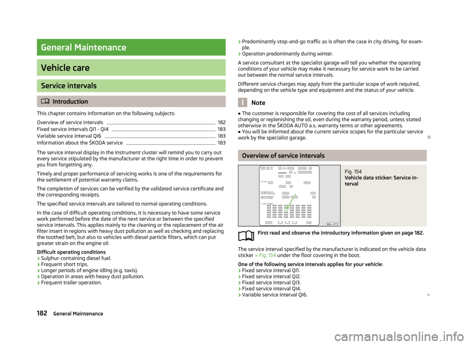
Fig. 154
Vehicle data sticker: Service in-
terval
First read and observe the introductory information given on page 182.
The service interval specified by the manufacturer is indicated on the vehicle data
sticker » Fig. 154 under the floor covering in the boot.
One of the following service intervals applies for your vehicle:
› Fixed service interval QI1.
› Fixed service interval QI2.
› Fixed service interval QI3.
› Fixed service interval QI4.
› Variable service interval QI6.
182General Maintenance
Page 207 of 266
Oil level within range CThe engine must be topped up with oil so that the oil level at least reaches the
range B
.
The engine consumes a little oil. The oil consumption may be as much as 0.5 l/
1 000 km depending on your style of driving and the conditions under which you operate your vehicle. Consumption may be slightly higher than this during thefirst 5 000 kilometres.
The oil level must be checked at regular intervals. We recommend after each time
you refuel or prior to making a long journey.
We recommend maintaining the oil level within the range
A
, but not above , if
the engine has been operating at high loads, for example, during a lengthy motor-
way trip during the summer months, towing a trailer or negotiating a high moun- tain pass.
The indicator light in the instrument cluster will indicate whether the oil level is
too low » page 17 ,
Engine oil . Check the oil level using the dipstick as soon
as possible. Add oil accordingly.
CAUTION
The oil level must not exceed the range A » Fig. 160 – there is a risk of damaging
the exhaust system.
Replenishing
First read and observe the introductory information and safety warn-
ings
on page 202.
›
Check the oil level » page 203.
›
Unscrew the cap of the engine oil filler opening » Fig. 158
on page 201.
›
Replenish the oil in portions of 0.5 litres in accordance with the correct specifi-
cations » page 203 .
›
Check the oil level » page 203.
›
Carefully screw on the oil filler opening cap and push the dipstick in fully.
Changing
First read and observe the introductory information and safety warn-ings
on page 202.
The engine oil must be changed according to prescribed service inter-vals » page 182 or according to the service interval display » page 30.
Coolant
Introduction
This chapter contains information on the following subjects:
Capacity
205
Checking the coolant level
205
Replenishing
206
The coolant consists of water with coolant additive. This mixture guarantees anti- freeze protection, protects the cooling/heater system against corrosion and pre-
vents lime formation.
Vehicles exported to countries with a mild climate are already factory-filled with
a coolant which offers antifreeze protection down to about -25 ℃. In these coun-
tries, the concentration of coolant additive should be at least 40%.
Vehicles exported to countries with a cold climate are already factory-filled with a
coolant which offers antifreeze protection down to about -35 °C. In these coun-
tries, the concentration of coolant additive should be at least 50%.
If a higher concentration of antifreeze is required for climatic reasons, the con-centration of coolant additive can be increased up to a maximum of 60% (anti-
freeze protection down to approx. -40 °C).
When refilling, only use the same antifreeze written on the antifreeze expansion tank » Fig. 161 on page 205.
204General Maintenance