trailer SKODA YETI 2013 1.G / 5L Owner's Guide
[x] Cancel search | Manufacturer: SKODA, Model Year: 2013, Model line: YETI, Model: SKODA YETI 2013 1.G / 5LPages: 266, PDF Size: 26.71 MB
Page 218 of 266
650 kg
670 kg
690 kg
730 kg
775 kg
Speed symbol
This indicates the maximum permissible vehicle speed with fitted tyres in each
category.
160 km/h
170 km/h
180 km/h
190 km/h
200 km/h
210 km/h
240 km/h
270 km/h
CAUTION
The information about the load index and the speed symbol is listed in your vehi-
cle documents.
Unidirectional tyres
First read and observe the introductory information and safety warn-
ings
on page 212.
The direction of rotation of the tyres is marked by arrows on the wall of the tyre.
The indicated direction of rotation must be adhered to in order to ensure the op- timal characteristics of these tyres.
These characteristics mainly relate to the following: › Increased driving stability.
› Reduced risk of aquaplaning.
› Reduced tyre noise and tyre wear.
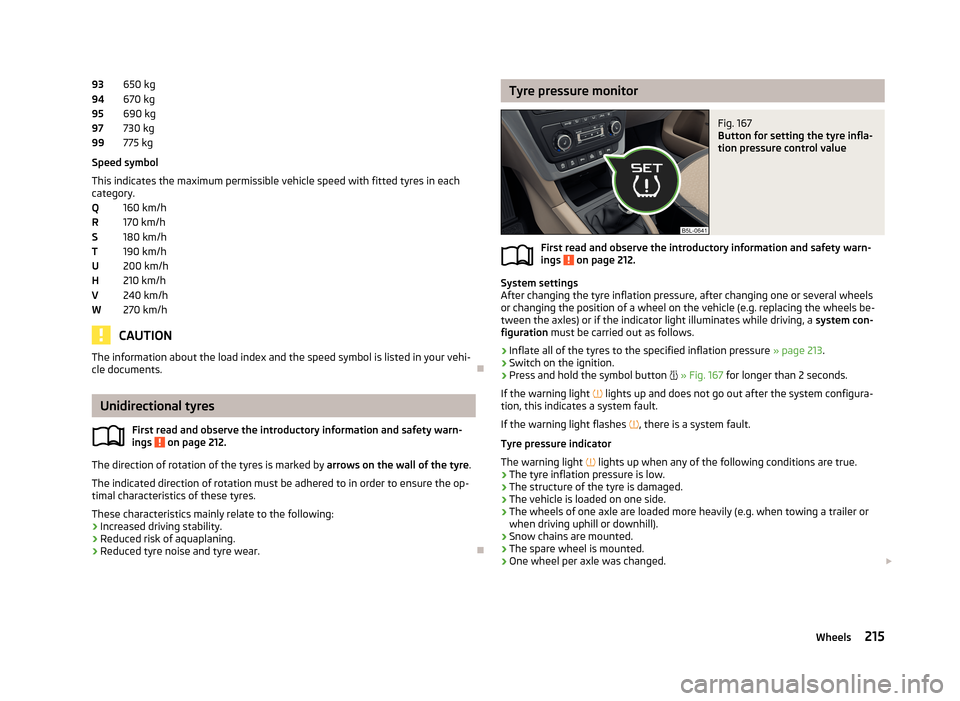
9394959799QRSTUHVWTyre pressure monitorFig. 167
Button for setting the tyre infla-
tion pressure control value
First read and observe the introductory information and safety warn-
ings on page 212.
System settings
After changing the tyre inflation pressure, after changing one or several wheels
or changing the position of a wheel on the vehicle (e.g. replacing the wheels be-
tween the axles) or if the indicator light illuminates while driving, a system con-
figuration must be carried out as follows.
›
Inflate all of the tyres to the specified inflation pressure » page 213.
›
Switch on the ignition.
›
Press and hold the symbol button
» Fig. 167 for longer than 2 seconds.
If the warning light
lights up and does not go out after the system configura-
tion, this indicates a system fault.
If the warning light flashes
, there is a system fault.
Tyre pressure indicator
The warning light
lights up when any of the following conditions are true.
› The tyre inflation pressure is low.
› The structure of the tyre is damaged.
› The vehicle is loaded on one side.
› The wheels of one axle are loaded more heavily (e.g. when towing a trailer or
when driving uphill or downhill).
› Snow chains are mounted.
› The spare wheel is mounted.
› One wheel per axle was changed.
215Wheels
Page 223 of 266
CAUTIONDo not put anything else except the reflective vest into the holder – risk of dam-
age to the holder.
Fire extinguisher
Fig. 172
Fire extinguisher
First read and observe the introductory information given on page 219.
The fire extinguisher is attached by two straps in a holder underneath the driver's
seat.
Removing/attaching
›
Loosen the two straps by pulling the buckles in the direction of the ar- row » Fig. 172 .
›
Remove the fire extinguisher.
Follow these steps in the reverse order for attachment.
Please read carefully the instructions which are attached to the fire extinguish-
er.
The fire extinguisher must be checked by an authorised person once a year. The
national legal requirements must be observed.
WARNINGThe fire extinguisher must always be secured safely so that they do not come loose when making an emergency braking or in a vehicle collision which could
cause injuries to occupants.Note■ The fire extinguisher must comply with national legal requirements.■Pay attention to the expiration date of the fire extinguisher. If the fire extin-
guisher is used after the expiration date, its proper function is not assured.■
The fire extinguisher is part of the scope of delivery in certain countries only.
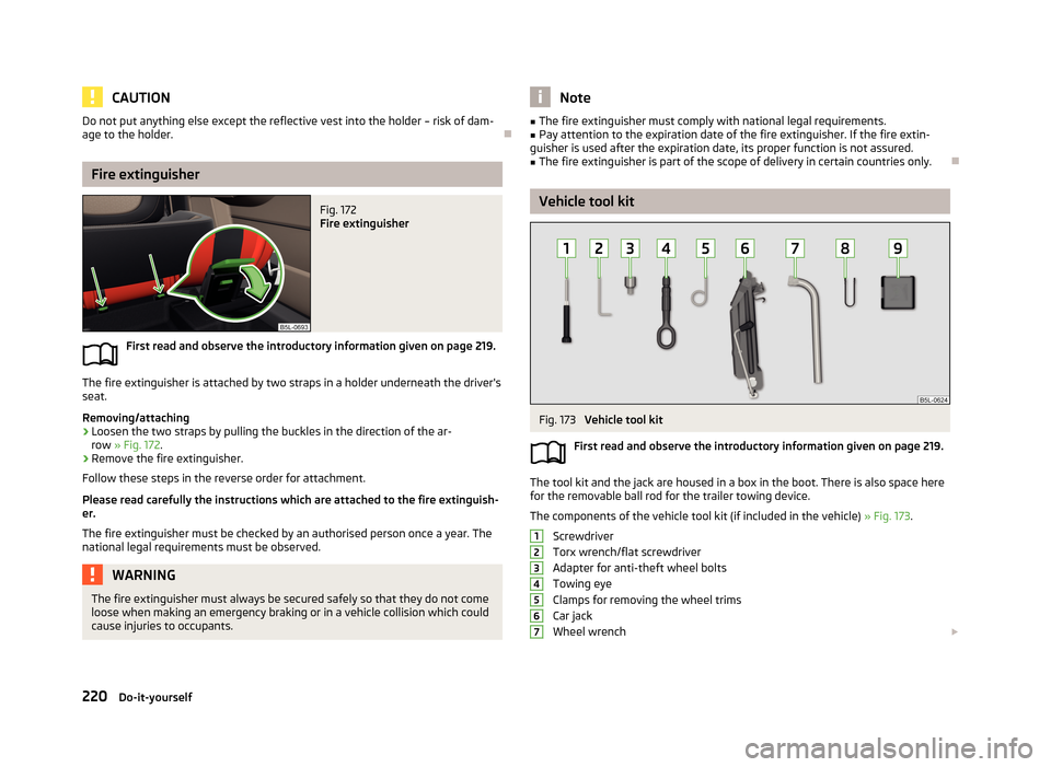
Vehicle tool kit
Fig. 173
Vehicle tool kit
First read and observe the introductory information given on page 219.
The tool kit and the jack are housed in a box in the boot. There is also space here
for the removable ball rod for the trailer towing device.
The components of the vehicle tool kit (if included in the vehicle) » Fig. 173.
Screwdriver
Torx wrench/flat screwdriver
Adapter for anti-theft wheel bolts
Towing eye
Clamps for removing the wheel trims
Car jack
Wheel wrench
1234567220Do-it-yourself
Page 225 of 266
PreparationFirst read and observe the introductory information and safety warn-
ings
on page 221.
Always change a wheel on a level surface as far as possible.
The following steps must be carried out before actually changing the wheel:
›
Have all of the occupants get out of the vehicle. While changing a tyre, the oc-
cupants of the vehicle should not stand on the road (they should instead remain
behind a crash barrier).
›
Switch off the engine.
›
Move the gearshift lever into Neutral or move the selector lever for the auto-
matic gearbox into position P.
›
Firmly apply the handbrake.
›
Uncouple any trailers.
›
Remove the vehicle tool kit » page 220 and the spare wheel » page 216 from
the boot.
Changing a wheel
First read and observe the introductory information and safety warn-
ings
on page 221.
›
Remove the full wheel trim » page 217 or caps » page 217 .
›
First of all slacken the anti-theft wheel bolt and then the other wheel
bolts » page 224 .
›
Jack up the vehicle until the wheel that needs changing is clear of the
ground » page 223 .
›
Unscrew the wheel bolts and place them on a clean surface (cloth, paper, etc.).
›
Remove the wheel carefully.
›
Attach the spare wheel and slightly screw on the wheel bolts.
›
Lower the vehicle.
›
Tighten the wheel bolts opposite each other using the wheel wrench (alternat-
ing crosswise). Tighten the anti-theft wheel bolt last » page 224.
›
Replace the wheel trim or the caps.
Note■
All bolts must be clean and must turn easily.■Under no circumstances grease or oil the wheel bolts!■
When fitting unidirectional tyres, ensure that the direction of rotation is cor-
rect » page 212 .
Follow-up tasks
First read and observe the introductory information and safety warn-
ings
on page 221.
The following steps must also be performed after changing the wheel.
›
Stow and attach the replaced wheel in the spare wheel well using a special bolt » page 216 .
›
Stow the tool kit in the space provided and secure using the band.
›
Check the tyre pressure on the installed spare wheel as soon as possible.
›
Have the tightening torque of the wheel bolts checked with a torque wrench
as soon as possible.
›
Replace the damaged wheel or consult a specialist garage about repair options.
Note
■ If it is determined that the wheel bolts are corroded and difficult to turn when
changing the wheel, the bolts must be replaced before checking the tightening
torque.■
Drive cautiously and only at a moderate speed until the tightening torque has
been checked.
222Do-it-yourself
Page 228 of 266
Note■Observe the manufacturer's usage instructions for the breakdown kit.■A new bottle of sealant can be purchased from ŠKODA Original Parts.■
Immediately replace the tyre that was repaired using the breakdown kit, or con-
sult a specialist garage about repair options.
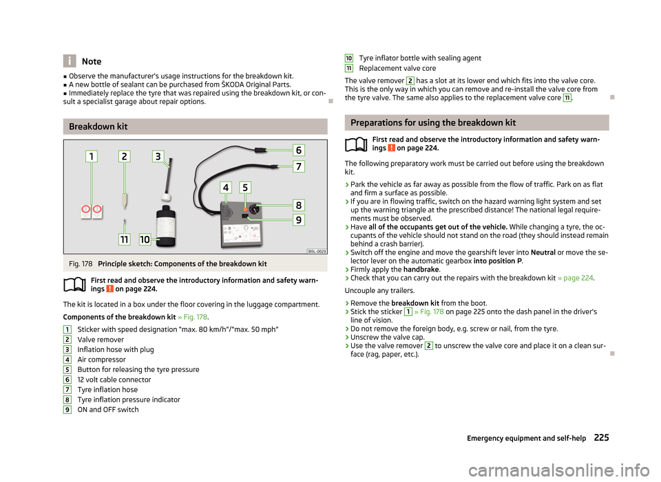
Breakdown kit
Fig. 178
Principle sketch: Components of the breakdown kit
First read and observe the introductory information and safety warn-
ings
on page 224.
The kit is located in a box under the floor covering in the luggage compartment.
Components of the breakdown kit » Fig. 178 .
Sticker with speed designation “max. 80 km/h”/“max. 50 mph” Valve remover
Inflation hose with plug
Air compressor
Button for releasing the tyre pressure
12 volt cable connector
Tyre inflation hose
Tyre inflation pressure indicator
ON and OFF switch
123456789Tyre inflator bottle with sealing agent
Replacement valve core
The valve remover 2
has a slot at its lower end which fits into the valve core.
This is the only way in which you can remove and re-install the valve core from
the tyre valve. The same also applies to the replacement valve core
11
.
Preparations for using the breakdown kit
First read and observe the introductory information and safety warn-
ings
on page 224.
The following preparatory work must be carried out before using the breakdown
kit.
›
Park the vehicle as far away as possible from the flow of traffic. Park on as flat and firm a surface as possible.
›
If you are in flowing traffic, switch on the hazard warning light system and setup the warning triangle at the prescribed distance! The national legal require-
ments must be observed.
›
Have all of the occupants get out of the vehicle. While changing a tyre, the oc-
cupants of the vehicle should not stand on the road (they should instead remain
behind a crash barrier).
›
Switch off the engine and move the gearshift lever into Neutral or move the se-
lector lever on the automatic gearbox into position P.
›
Firmly apply the handbrake.
›
Check that you can carry out the repairs with the breakdown kit » page 224.
Uncouple any trailers.
›
Remove the breakdown kit from the boot.
›
Stick the sticker
1
» Fig. 178 on page 225 onto the dash panel in the driver's
line of vision.
›
Do not remove the foreign body, e.g. screw or nail, from the tyre.
›
Unscrew the valve cap.
›
Use the valve remover
2
to unscrew the valve core and place it on a clean sur-
face (rag, paper, etc.).
1011
225Emergency equipment and self-help
Page 231 of 266
Negative cable - colour coding in the majority of cases is black.
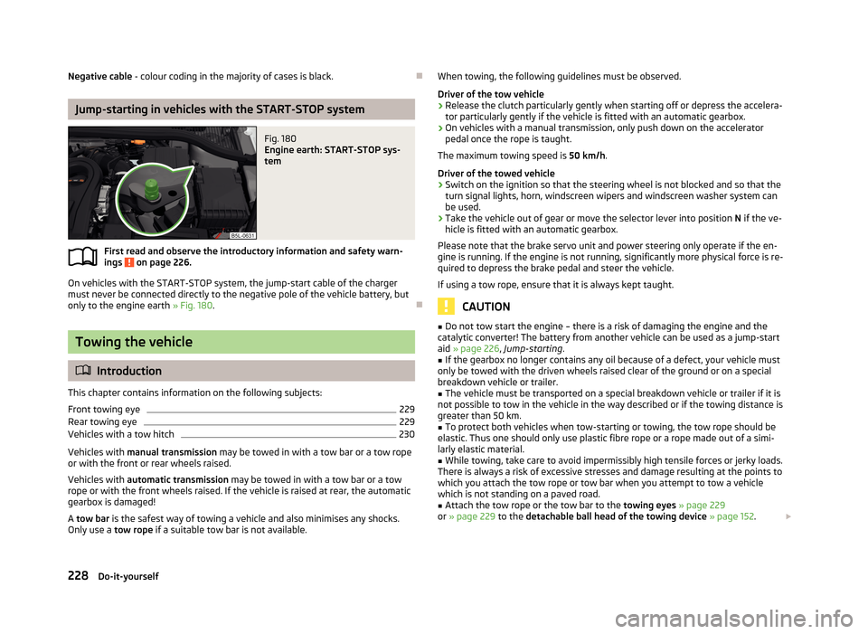
Jump-starting in vehicles with the START-STOP system
Fig. 180
Engine earth: START-STOP sys-
tem
First read and observe the introductory information and safety warn- ings on page 226.
On vehicles with the START-STOP system, the jump-start cable of the charger
must never be connected directly to the negative pole of the vehicle battery, but
only to the engine earth » Fig. 180.
Towing the vehicle
Introduction
This chapter contains information on the following subjects:
Front towing eye
229
Rear towing eye
229
Vehicles with a tow hitch
230
Vehicles with manual transmission may be towed in with a tow bar or a tow rope
or with the front or rear wheels raised.
Vehicles with automatic transmission may be towed in with a tow bar or a tow
rope or with the front wheels raised. If the vehicle is raised at rear, the automatic
gearbox is damaged!
A tow bar is the safest way of towing a vehicle and also minimises any shocks.
Only use a tow rope if a suitable tow bar is not available.
When towing, the following guidelines must be observed.
Driver of the tow vehicle›
Release the clutch particularly gently when starting off or depress the accelera-
tor particularly gently if the vehicle is fitted with an automatic gearbox.
›
On vehicles with a manual transmission, only push down on the accelerator pedal once the rope is taught.
The maximum towing speed is 50 km/h.
Driver of the towed vehicle
›
Switch on the ignition so that the steering wheel is not blocked and so that the
turn signal lights, horn, windscreen wipers and windscreen washer system can be used.
›
Take the vehicle out of gear or move the selector lever into position N if the ve-
hicle is fitted with an automatic gearbox.
Please note that the brake servo unit and power steering only operate if the en-
gine is running. If the engine is not running, significantly more physical force is re- quired to depress the brake pedal and steer the vehicle.
If using a tow rope, ensure that it is always kept taught.
CAUTION
■ Do not tow start the engine – there is a risk of damaging the engine and the
catalytic converter! The battery from another vehicle can be used as a jump-start aid » page 226 , Jump-starting .■
If the gearbox no longer contains any oil because of a defect, your vehicle must
only be towed with the driven wheels raised clear of the ground or on a special
breakdown vehicle or trailer.
■
The vehicle must be transported on a special breakdown vehicle or trailer if it is
not possible to tow in the vehicle in the way described or if the towing distance is
greater than 50 km.
■
To protect both vehicles when tow-starting or towing, the tow rope should be
elastic. Thus one should only use plastic fibre rope or a rope made out of a simi-
larly elastic material.
■
While towing, take care to avoid impermissibly high tensile forces or jerky loads.
There is always a risk of excessive stresses and damage resulting at the points to which you attach the tow rope or tow bar when you attempt to tow a vehicle
which is not standing on a paved road.
■
Attach the tow rope or the tow bar to the towing eyes » page 229
or » page 229 to the detachable ball head of the towing device » page 152 .
228Do-it-yourself
Page 247 of 266
Technical data
Technical data
Vehicle data
Introduction
This chapter contains information on the following subjects:
Vehicle identification data
244
Dimensions
245
angle and gradeability
246
Vehicle-specific details per engine type
247
The details given in the vehicle's technical documentation always take prece-
dence over the details in the Owner's Manual.
The listed performance values were determined without performance-reducing
equipment, e.g. air conditioning system.
Vehicle identification data
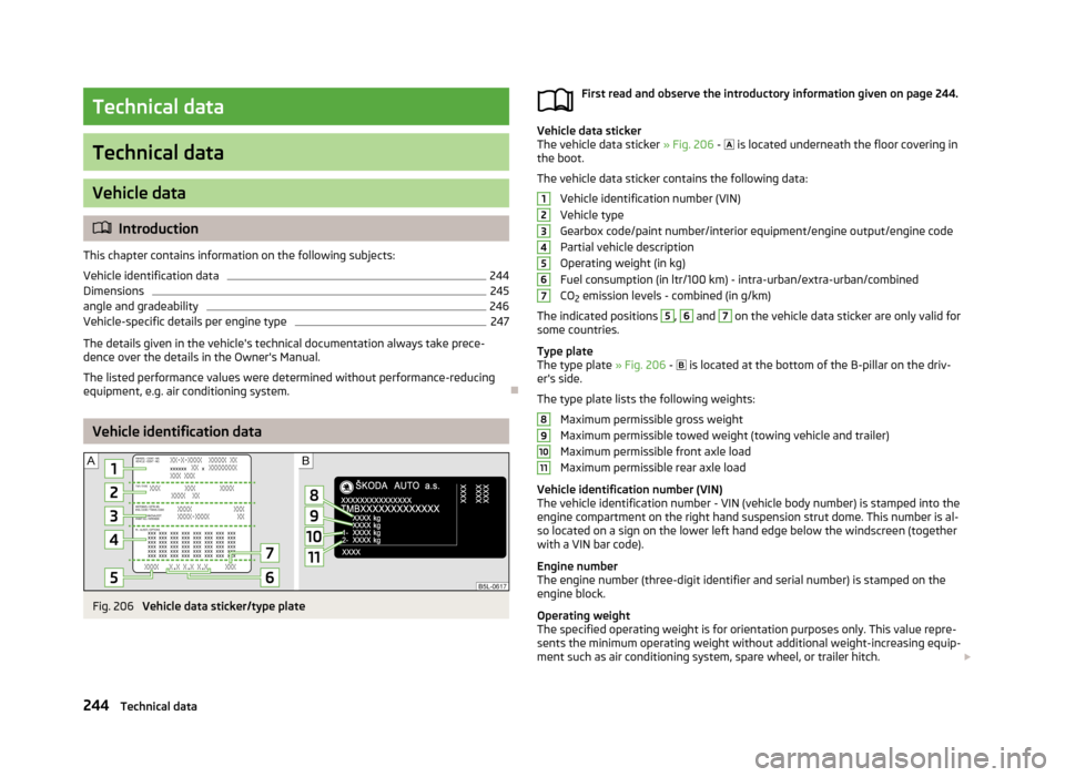
Fig. 206
Vehicle data sticker/type plate
First read and observe the introductory information given on page 244.
Vehicle data sticker
The vehicle data sticker » Fig. 206 - is located underneath the floor covering in
the boot.
The vehicle data sticker contains the following data: Vehicle identification number (VIN)
Vehicle type
Gearbox code/paint number/interior equipment/engine output/engine code Partial vehicle description
Operating weight (in kg) Fuel consumption (in ltr/100 km) - intra-urban/extra-urban/combined
CO 2 emission levels - combined (in g/km)
The indicated positions
5
,
6
and
7
on the vehicle data sticker are only valid for
some countries.
Type plate
The type plate » Fig. 206 -
is located at the bottom of the B-pillar on the driv-
er's side.
The type plate lists the following weights: Maximum permissible gross weight
Maximum permissible towed weight (towing vehicle and trailer)
Maximum permissible front axle load
Maximum permissible rear axle load
Vehicle identification number (VIN)
The vehicle identification number - VIN (vehicle body number) is stamped into the
engine compartment on the right hand suspension strut dome. This number is al-so located on a sign on the lower left hand edge below the windscreen (together
with a VIN bar code).
Engine number
The engine number (three-digit identifier and serial number) is stamped on the
engine block.
Operating weight
The specified operating weight is for orientation purposes only. This value repre- sents the minimum operating weight without additional weight-increasing equip-
ment such as air conditioning system, spare wheel, or trailer hitch.
1234567891011244Technical data
Page 248 of 266
The operating weight also contains the weight of the driver (75 kg), the weight of
the operating fluids, the tool kit, and a fuel tank filled to 90 % capacity.
It is possible to calculate the approximate loading capacity from the difference
between the permissible total weight and the operating weight »
.
The payload consists of the following components. › The weight of the rider.
› The weight of all luggage and other loads.
› The weight of the roof, including the roof rack system.
› The weight of the equipment that are excluded from the operating weight.
› The trailer nose weight with trailer (max. 80 kg and 85 kg 1)
).
Fuel consumption and CO 2 emissions according to ECE regulations and EU
directives
The measurement of the intra-urban cycle begins with a cold start of the engine.
Afterwards urban driving is simulated.
In the extra-urban driving cycle, the vehicle is accelerated and decelerated in all
gears, corresponding to daily routine driving conditions. The driving speed varies
between 0 and 120 km/h.
The calculation of the combined fuel consumption considers a weighting of about 37 % for the intra-urban cycle and 63 % for the extra-urban cycle.
WARNINGDo not exceed the specified maximum permissible weights – risk of accident
and damage!
Note
■ If required, you can find out the precise weight of your vehicle at a specialist ga-
rage.■
The fuel consumption and emission values have been determined in accordance
with rules and under conditions set out by legal or technical requirements for de-
termining operational and technical data for motor vehicles.
■
Depending on the range of equipment, style of driving, traffic situation, weather
influences and vehicle condition, consumption values may deviate from the indi-
cated values.
Dimensions
First read and observe the introductory information given on page 244.
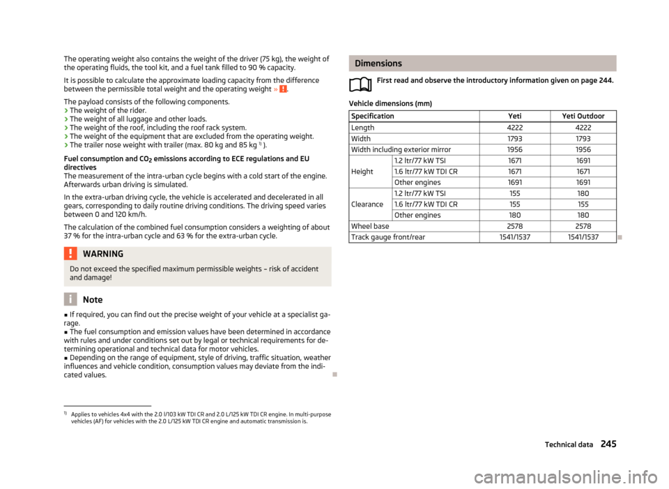
Vehicle dimensions (mm)
SpecificationYetiYeti OutdoorLength42224222Width17931793Width including exterior mirror19561956
Height
1.2 ltr/77 kW TSI167116911.6 ltr/77 kW TDI CR16711671Other engines16911691
Clearance
1.2 ltr/77 kW TSI1551801.6 ltr/77 kW TDI CR155155Other engines180180Wheel base25782578Track gauge front/rear1541/15371541/1537
1)
Applies to vehicles 4x4 with the 2.0 l/103 kW TDI CR and 2.0 L/125 kW TDI CR engine. In multi-purpose
vehicles (AF) for vehicles with the 2.0 L/125 kW TDI CR engine and automatic transmission is.
245Technical data
Page 250 of 266
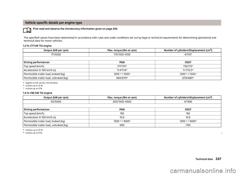
Vehicle-specific details per engine typeFirst read and observe the introductory information given on page 244.The specified values have been determined in accordance with rules and under conditions set out by legal or technical requirements for determining operational and
technical data for motor vehicles.
1.2 ltr./77 kW TSI engine
Output (kW per rpm)Max. torque (Nm at rpm)Number of cylinders/Displacement (cm 3
)77/5000175/1550-41004/1197 Driving performancesMG6DSG7Top speed (km/h)177/175 a)176/173 a)Acceleration 0-100 km/h (s)11.4/11.8 a)11.7/12.0 a)Permissible trailer load, braked (kg)1200 b)
/ 1500 c)1200 b)
/ 1500 c)Permissible trailer load, unbraked (kg)660/670 a)670/680 a)a)
Applies to the version Yeti Outdoor.
b)
Inclines up to 12 %.
c)
Inclines up to 8 %.
1.4 ltr./90 kW TSI engine
Output (kW per rpm)Max. torque (Nm at rpm)Number of cylinders/displacement (cm 3
)90/5000200/1500-40004/1390 Driving performancesMG6DSG7Top speed (km/h)185182Acceleration 0-100 km/h (s)10.610.6Permissible trailer load, braked (kg)1300 a)
/ 1600 b)1300 a)
/ 1600 b)Permissible trailer load, unbraked (kg)690700a)
Inclines up to 12 %.
b)
Inclines up to 8 %.
247Technical data
Page 251 of 266
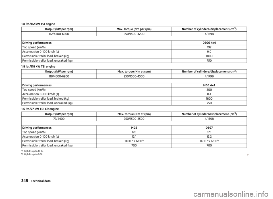
1.8 ltr./112 kW TSI engineOutput (kW per rpm)Max. torque (Nm per rpm)Number of cylinders/displacement (cm3
)112/4300-6200250/1500-42004/1798 Driving performancesDSG6 4x4Top speed (km/h)192Acceleration 0-100 km/h (s)9.0Permissible trailer load, braked (kg)1800Permissible trailer load, unbraked (kg)750
1.8 ltr./118 kW TSI engine
Output (kW per rpm)Max. torque (Nm at rpm)Number of cylinders/displacement (cm 3
)118/4500-6200250/1500-45004/1798 Driving performancesMG6 4x4Top speed (km/h)200Acceleration 0-100 km/h (s)8.4Permissible trailer load, braked (kg)1800Permissible trailer load, unbraked (kg)750
1.6 ltr./77 kW TDI CR engine
Output (kW per rpm)Max. torque (Nm at rpm)Number of cylinders/Displacement (cm 3
)77/4400250/1500-25004/1598 Driving performancesMG5DSG7Top speed (km/h)176175Acceleration 0-100 km/h (s)12.112.2Permissible trailer load, braked (kg)1400 a)
/ 1700 b)1400 a)
/ 1700 b)Permissible trailer load, unbraked (kg)700700a)
Uphills up to 12 %.
b)
Uphills up to 8 %.
248Technical data
Page 252 of 266
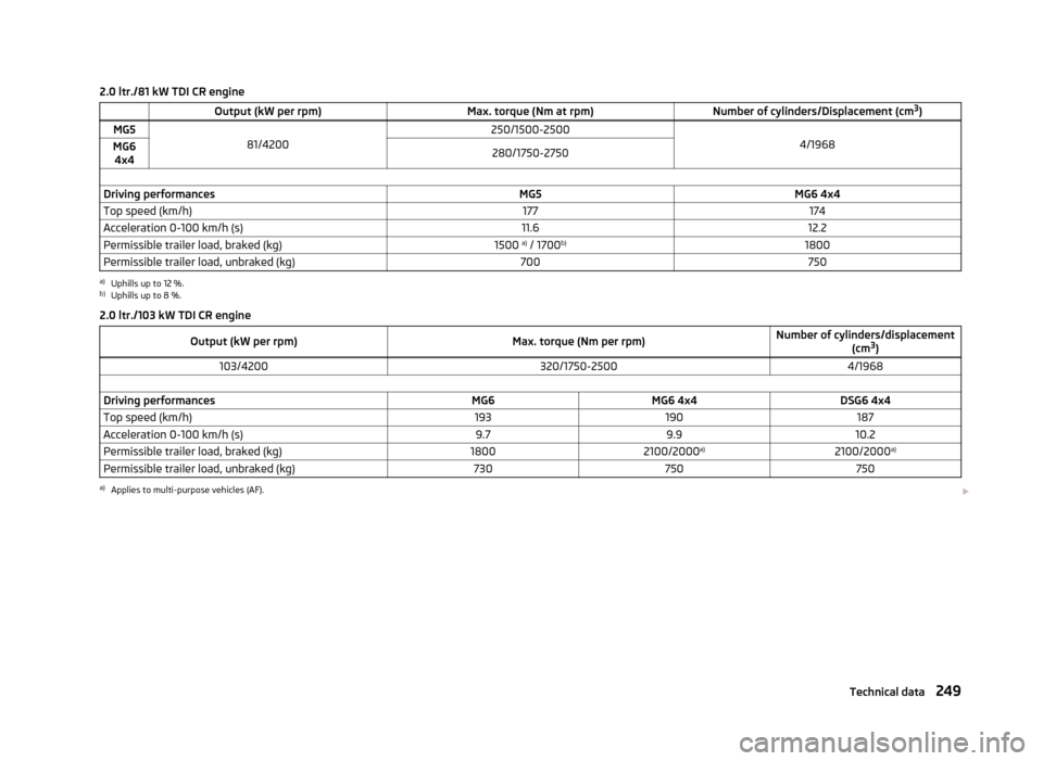
2.0 ltr./81 kW TDI CR engine Output (kW per rpm)Max. torque (Nm at rpm)Number of cylinders/Displacement (cm3
)MG581/4200250/1500-25004/1968MG6
4x4280/1750-2750 Driving performancesMG5MG6 4x4Top speed (km/h)177174Acceleration 0-100 km/h (s)11.612.2Permissible trailer load, braked (kg)1500 a)
/ 1700 b)1800Permissible trailer load, unbraked (kg)700750a)
Uphills up to 12 %.
b)
Uphills up to 8 %.
2.0 ltr./103 kW TDI CR engine
Output (kW per rpm)Max. torque (Nm per rpm)Number of cylinders/displacement (cm3
)103/4200320/1750-25004/1968 Driving performancesMG6MG6 4x4DSG6 4x4Top speed (km/h)193190187Acceleration 0-100 km/h (s)9.79.910.2Permissible trailer load, braked (kg)18002100/2000 a)2100/2000 a)Permissible trailer load, unbraked (kg)730750750a)
Applies to multi-purpose vehicles (AF).
249Technical data