heater SKODA YETI 2013 1.G / 5L Owner's Manual
[x] Cancel search | Manufacturer: SKODA, Model Year: 2013, Model line: YETI, Model: SKODA YETI 2013 1.G / 5LPages: 266, PDF Size: 26.71 MB
Page 58 of 266
Visibility
Introduction
This chapter contains information on the following subjects:
Windscreen and rear window heater
55
Sun visors
55
Windscreen and rear window heater
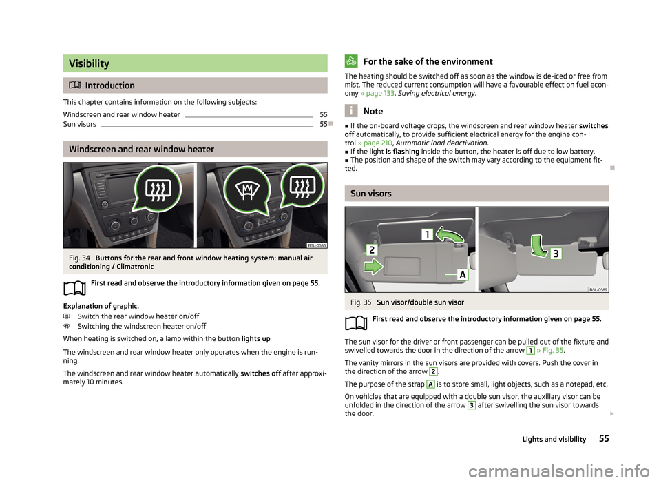
Fig. 34
Buttons for the rear and front window heating system: manual air
conditioning / Climatronic
First read and observe the introductory information given on page 55.
Explanation of graphic.Switch the rear window heater on/off
Switching the windscreen heater on/off
When heating is switched on, a lamp within the button lights up
The windscreen and rear window heater only operates when the engine is run-
ning.
The windscreen and rear window heater automatically switches off after approxi-
mately 10 minutes.
For the sake of the environmentThe heating should be switched off as soon as the window is de-iced or free from
mist. The reduced current consumption will have a favourable effect on fuel econ-
omy » page 133 , Saving electrical energy .
Note
■
If the on-board voltage drops, the windscreen and rear window heater switches
off automatically, to provide sufficient electrical energy for the engine con-
trol » page 210 , Automatic load deactivation .■
If the light is flashing inside the button, the heater is off due to low battery.
■
The position and shape of the switch may vary according to the equipment fit-
ted.
Sun visors
Fig. 35
Sun visor/double sun visor
First read and observe the introductory information given on page 55.
The sun visor for the driver or front passenger can be pulled out of the fixture and
swivelled towards the door in the direction of the arrow
1
» Fig. 35 .
The vanity mirrors in the sun visors are provided with covers. Push the cover in
the direction of the arrow
2
.
The purpose of the strap
A
is to store small, light objects, such as a notepad, etc.
On vehicles that are equipped with a double sun visor, the auxiliary visor can be
unfolded in the direction of the arrow
3
after swivelling the sun visor towards
the door.
55Lights and visibility
Page 62 of 266
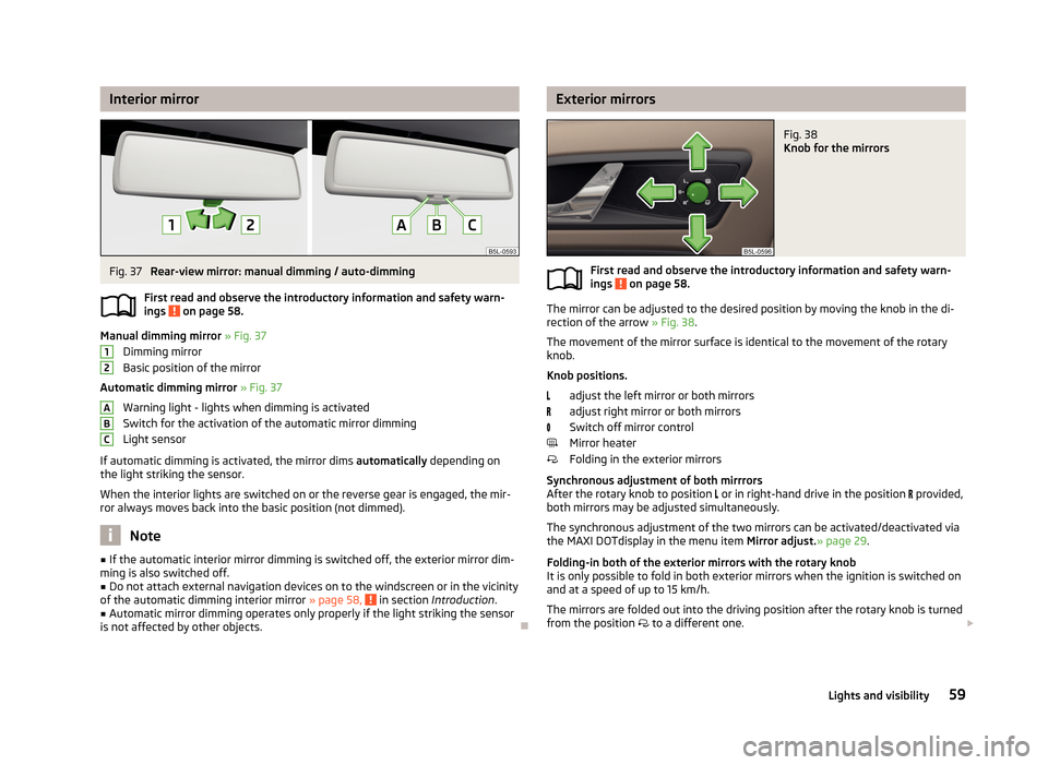
Interior mirrorFig. 37
Rear-view mirror: manual dimming / auto-dimming
First read and observe the introductory information and safety warn- ings
on page 58.
Manual dimming mirror » Fig. 37
Dimming mirror
Basic position of the mirror
Automatic dimming mirror » Fig. 37
Warning light - lights when dimming is activated Switch for the activation of the automatic mirror dimmingLight sensor
If automatic dimming is activated, the mirror dims automatically depending on
the light striking the sensor.
When the interior lights are switched on or the reverse gear is engaged, the mir- ror always moves back into the basic position (not dimmed).
Note
■ If the automatic interior mirror dimming is switched off, the exterior mirror dim-
ming is also switched off.■
Do not attach external navigation devices on to the windscreen or in the vicinity
of the automatic dimming interior mirror » page 58, in section Introduction .
■
Automatic mirror dimming operates only properly if the light striking the sensor
is not affected by other objects.
12ABCExterior mirrorsFig. 38
Knob for the mirrors
First read and observe the introductory information and safety warn-
ings on page 58.
The mirror can be adjusted to the desired position by moving the knob in the di-
rection of the arrow » Fig. 38.
The movement of the mirror surface is identical to the movement of the rotary
knob.
Knob positions. adjust the left mirror or both mirrors
adjust right mirror or both mirrors
Switch off mirror control
Mirror heater
Folding in the exterior mirrors
Synchronous adjustment of both mirrrors
After the rotary knob to position
or in right-hand drive in the position
provided,
both mirrors may be adjusted simultaneously.
The synchronous adjustment of the two mirrors can be activated/deactivated via
the MAXI DOTdisplay in the menu item Mirror adjust.» page 29.
Folding-in both of the exterior mirrors with the rotary knob
It is only possible to fold in both exterior mirrors when the ignition is switched on and at a speed of up to 15 km/h.
The mirrors are folded out into the driving position after the rotary knob is turned from the position
to a different one.
59Lights and visibility
Page 63 of 266
Folding-in both of the exterior mirrors using the remote control keyThe entire mirror can be folded by pressing the symbol button on the remote
control key for 2 seconds. All windows must be closed.
The exterior mirror is folded back into the driving position when the ignition isswitched on.
Automatic dimming mirror
The exterior mirrors are dimmed together with the automatic dimming interior
mirror » page 59 .
Fold in passenger's mirror
On vehicles fitted with the memory function for the driver's seat » page 63, the
mirror tilts down slightly when the reverse gear is engaged and the rotary knob is
in the position
or in position
on vehicles with right-hand drive » Fig. 38 . This
provides an aid in seeing the kerb of the pavement when parking the car.
The mirror returns into its initial position after the rotary knob is moved out of po-
sition
(or position
on vehicles with right-hand drive) and put into another posi-
tion or if the speed is more than 15 km/h.
This mode can be enabled or disabled via the Maxi DOT display in the Travel
mode » page 29 menu option.
Memory function for mirrors
On vehicles fitted with a memory function for the driver seat, the relevant setting for the exterior mirrors can also be stored automatically when the seat position is
stored » page 63 .WARNINGDo not touch the exterior mirror surfaces, if the exterior mirror heating is
switched on - hazard of burning.
CAUTION
Never mechanically fold in or fold back the exterior mirrors with the fold-in func-
tion by hand as this will damage the electric drive.
Note
■
The mirror heater only operates when the engine is running and up to an out-
side temperature of +35 ℃.■
If the power setting function fails at any time, the exterior mirrors can be set by
hand by pressing on the edge of the mirror surface.
60Using the system
Page 67 of 266
When automatic storage is activated, the current positions of the driver's seat
and the external mirrors are saved in the memory of the remote control key each
time the vehicle is locked. When the vehicle is next unlocked using the same key,
the driver's seat and the external mirrors assume the positions stored in the
memory of this key 1)
.
Saving front passenger mirror settings when reversing›
Unlock the vehicle with the remote control key.
›
Switch on the ignition.
›
Adjust the rotary knob for the mirrors to the position
or in right-hand drive to
the position » page 59 .
›
Engage reverse gear.
›
Adjust the front passenger's mirror to the desired position » page 59.
›
Disengage reverse gear.
The adjusted position of the exterior mirror is stored in the remote control key
memory.
Enable automatic storage
›
Unlock the vehicle with the remote control key.
›
Press and hold any memory button
B
» Fig. 42 on page 63. After the seat has
assumed the position stored under this button, at the same time press the but-
ton
on the remote control key within 10 seconds.
The successful activation of the automatic storage function for each key is con-
firmed by an acoustic signal.
The seat and external mirror positions which are already saved in the memory
button are not saved in the memory of the key.
The seat can be adjusted to the required position if necessary » page 62.
After locking the vehicle, the current positions of the driver's seat and the exter-
nal mirrors are saved in the memory of the remote control key.
Disable the function of automatic storage
›
Unlock the vehicle with the remote control key.
›
Press and hold the SET button
A
» Fig. 42 on page 63. At the same time, press
the button on the remote control key within 10 seconds.
The successful deactivation of the automatic storage function for each key is con-
firmed by an acoustic signal.
Stopping the ongoing adjustment›Press any button on the driver's seat.
or›
Press the button on the remote control key.
Front seat functions
Introduction
This chapter contains information on the following subjects:
Front seat heating
64
Front armrest
65
Folding front passenger seat
66
Front seat heating
Fig. 43
Heated front seats
First read and observe the introductory information given on page 64.
Explanation of graphic » Fig. 43
Control the seat heater on the front left seat
Control the seat heater on the front right seat
The seat backrests and seats can be heated electrically.
1)
The vehicle must be locked and unlocked with the same key to save the seat and exterior mirror po-
sition to the key.
64Using the system
Page 68 of 266
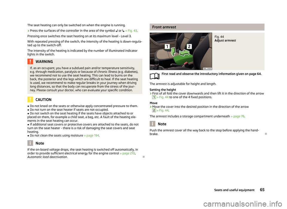
The seat heating can only be switched on when the engine is running.›
Press the surfaces of the controller in the area of the symbol or » Fig. 43 .
Pressing once switches the seat heating on at its maximum level - Level 3.
With repeated pressing of the switch, the intensity of the heating is down-regula-
ted up to the switch-off.
The intensity of the heating is indicated by the number of illuminated indicator
lights in the switch.WARNINGIf, as an occupant, you have a subdued pain and/or temperature sensitivity,
e.g. through medication, paralysis or because of chronic illness (e.g. diabetes),
we recommend not to use the seat heating. This can lead to burns on the
back, the posterior and the legs which are difficult to heal. If the seat heating
is used, we recommend to make regular breaks in your journey when driving
long distances, so that the body can recuperate from the stress of the jour-
ney. Please consult your doctor, who can evaluate your specific condition.
CAUTION
■ Do not kneel on the seats or otherwise apply concentrated pressure to them.■Do not turn on the seat heater if seats are not occupied.■
Do not switch on the seat heating if the seats have objects attached to or
placed on them, for example a child seat, a bag, etc. A fault of the heating ele-
ments in the seat heating can occur.
■
If additional seat covers or protective covers are attached to the seats, do not
turn on the seat heater - there is a risk of damaging the seat covers and seat
heating.
■
Do not clean the seats using moisture » page 194.
Note
If the on-board voltage drops, the seat heating is switched off automatically, in
order to provide sufficient electrical energy for the engine control » page 210,
Automatic load deactivation .
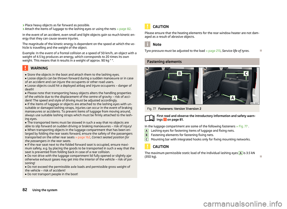
Front armrestFig. 44
Adjust armrest
First read and observe the introductory information given on page 64.
The armrest is adjustable for height and length.
Setting the height
›
First of all fold the cover downwards and then lift it in the direction of the arrow
1
» Fig. 44 to one of the 4 fixed positions.
Move
›
Move the cover into the desired position in the direction of the arrow
2
» Fig. 44 .
The armrest includes a storage compartment underneath » page 76.
Note
Push the armrest cover all the way back to the stop before applying the hand-
brake.
65Seats and useful equipment
Page 85 of 266
›Place heavy objects as far forward as possible.›Attach the items of luggage to the lashing eyes or using the nets
» page 82.
In the event of an accident, even small and light objects gain so much kinetic en-
ergy that they can cause severe injuries.
The magnitude of the kinetic energy is dependent on the speed at which the ve-
hicle is travelling and the weight of the object.
Example: In the event of a frontal collision at a speed of 50 km/h, an object with a
weight of 4.5 kg produces an energy, which corresponds to 20 times its own
weight. This means that it results in a weight of approx. 90 kg “ ”.WARNING■ Store the objects in the boot and attach them to the lashing eyes.■Loose objects can be thrown forward during a sudden manoeuvre or in case
of an accident and can injure the occupants or other road users.■
Loose objects could hit a deployed airbag and injure occupants – danger of
death!
■
Please note that transporting heavy objects alters the handling properties
of the vehicle due to the displacement of the centre of gravity – risk of acci-
dent! The speed and style of driving must be adjusted accordingly.
■
If the items of luggage or objects are attached to the lashing eyes with un-
suitable or damaged lashing straps, injuries can occur in the event of braking manoeuvres or accidents. To prevent items of luggage from moving around,
always use suitable lashing straps which must be firmly attached to the lash-
ing eyes.
■
The transported items must be stowed in such a way that no objects are
able to slip forward on sudden driving or braking manoeuvres – risk of injury!
■
When transporting objects in the luggage compartment that has been en-
larged by folding the rear seats forward, ensure the safety of the passengers transported on the other rear seats » page 162, Correct seated position for
the passengers in the rear seats .
■
If the rear seat next to the folded forward seat is occupied, ensure maxi-
mum safety, e.g. by placing the goods to be transported in such a way that the
seat is prevented from folding back in case of a rear collision.
■
Do not drive with the luggage compartment lid fully opened or slightly ajar
otherwise exhaust gases may get into the interior of the vehicle – risk of poi-
soning!
■
Do not exceed the permissible axle loads and permissible gross weight of
the vehicle – risk of accident!
■
Do not transport people in the boot!
CAUTIONPlease ensure that the heating elements for the rear window heater are not dam-
aged as a result of abrasive objects.
Note
Tyre pressure must be adjusted to the load » page 213, Service life of tyres .
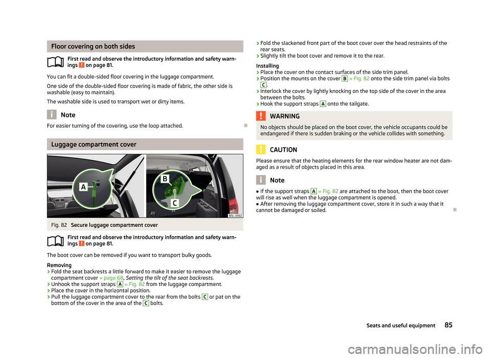
Fastening elements
Fig. 77
Fasteners: Version 1/version 2
First read and observe the introductory information and safety warn- ings
on page 81.
In the luggage compartment are some of the following fasteners » Fig. 77 .
Lashing eyes for fastening items of luggage and fixing nets.
Fastening elements for fastening fixing nets.
Mounting bar with integrated hooks only for fixing mounting networks.
CAUTION
The maximum permissible static load of the individual lashing eyes A is 3.5 kN
(350 kg).
ABC82Using the system
Page 88 of 266
Floor covering on both sidesFirst read and observe the introductory information and safety warn-
ings
on page 81.
You can fit a double-sided floor covering in the luggage compartment.
One side of the double-sided floor covering is made of fabric, the other side is
washable (easy to maintain).
The washable side is used to transport wet or dirty items.
Note
For easier turning of the covering, use the loop attached.
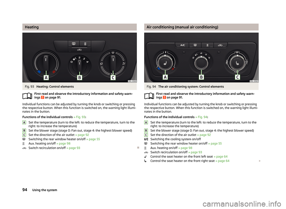
Luggage compartment cover
Fig. 82
Secure luggage compartment cover
First read and observe the introductory information and safety warn- ings
on page 81.
The boot cover can be removed if you want to transport bulky goods.
Removing
›
Fold the seat backrests a little forward to make it easier to remove the luggage
compartment cover » page 68, Setting the tilt of the seat backrests .
›
Unhook the support straps
A
» Fig. 82 from the luggage compartment.
›
Place the cover in the horizontal position.
›
Pull the luggage compartment cover to the rear from the bolts
C
or pat on the
bottom of the cover in the area of the
C
bolts.
› Fold the slackened front part of the boot cover over the head restraints of the
rear seats.›
Slightly tilt the boot cover and remove it to the rear.
Installing
›
Place the cover on the contact surfaces of the side trim panel.
›
Position the mounts on the cover
B
» Fig. 82 onto the side trim panel via bolts
C
.
›
Interlock the cover by lightly knocking on the top side of the cover in the area
between the bolts.
›
Hook the support straps
A
onto the tailgate.
WARNINGNo objects should be placed on the boot cover, the vehicle occupants could be
endangered if there is sudden braking or the vehicle collides with something.
CAUTION
Please ensure that the heating elements for the rear window heater are not dam-
aged as a result of objects placed in this area.
Note
■ If the support straps A » Fig. 82 are attached to the boot, then the boot cover
will rise as well when the luggage compartment is opened.■
After removing the luggage compartment cover, store it in such a way that it
cannot be damaged or soiled.
85Seats and useful equipment
Page 97 of 266
HeatingFig. 93
Heating: Control elements
First read and observe the introductory information and safety warn- ings
on page 91.
Individual functions can be adjusted by turning the knob or switching or pressingthe respective button. When this function is switched on, the warning light illumi-
nates in the button.
Functions of the individual controls » Fig. 93 :
Set the temperature (turn to the left: to reduce the temperature, turn to the
right: to increase the temperature)
Set the blower stage (stage 0: Fan out, stage 4: the highest blower speed) Set the direction of the air outlet » page 92
Switching the rear window heater on/off » page 55
Aux. heating on/off » page 98
Switch recirculation on/off » page 93
ABCAir conditioning (manual air conditioning)Fig. 94
The air conditioning system: Control elements
First read and observe the introductory information and safety warn- ings
on page 91.
Individual functions can be adjusted by turning the knob or switching or pressing the respective button. When this function is switched on, the warning light illumi-
nates in the button.
Functions of the individual controls » Fig. 94 :
Set the temperature (turn to the left: to reduce the temperature, turn to the
right: to increase the temperature)
Set the blower stage (stage 0: Fan out, stage 4: the highest blower speed) Set the direction of the air outlet » page 92
Switching the cooling system on/off Switching the rear window heater on/off » page 55
Aux. heating on/off » page 98
Switch recirculation on/off » page 93
Control the seat heater on the front left seat » page 64
Control the seat heater on the front right seat » page 64
ABC94Using the system
Page 98 of 266
NoteThe warning light in the button lights after activation, even if not all of the
conditions for the function of the cooling system have been met. By lighting up of the indicator light in the button, the operational readiness of the cooling system
is signalled.
Climatronic (automatic air conditioning)
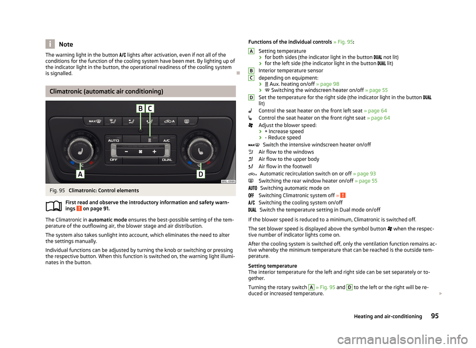
Fig. 95
Climatronic: Control elements
First read and observe the introductory information and safety warn- ings
on page 91.
The Climatronic in automatic mode ensures the best-possible setting of the tem-
perature of the outflowing air, the blower stage and air distribution.
The system also takes sunlight into account, which eliminates the need to alterthe settings manually.
Individual functions can be adjusted by turning the knob or switching or pressing the respective button. When this function is switched on, the warning light illumi-
nates in the button.
Functions of the individual controls » Fig. 95 :
Setting temperature
› for both sides (the indicator light in the button
not lit)
› for the left side (the indicator light in the button
lit)
Interior temperature sensor
depending on equipment:
›
Aux. heating on/off » page 98
›
Switching the windscreen heater on/off » page 55
Set the temperature for the right side (the indicator light in the button
lit)
Control the seat heater on the front left seat » page 64
Control the seat heater on the front right seat » page 64
Adjust the blower speed:
› + Increase speed
› - Reduce speed
Switch the intensive windscreen heater on/off
Air flow to the windows
Air flow to the upper body
Air flow in the footwell
Automatic recirculation switch on or off » page 93
Switching the rear window heater on/off » page 55
Switching automatic mode on
Switching Climatronic system off »
Switching the cooling system on/off
Switch the temperature setting in Dual mode on/off
If the blower speed is reduced to a minimum, Climatronic is switched off. The set blower speed is displayed above the symbol button
when the respec-
tive number of indicator lights come on.
After the cooling system is switched off, only the ventilation function remains ac-tive whereby the minimum temperature that can be reached is the outside tem-
perature.
Setting temperature
The interior temperature for the left and right side can be set separately or to-
gether.
Turning the rotary switch
A
» Fig. 95 and
D
to the left or the right will be re-
duced or increased temperature.
ABCD95Heating and air-conditioning
Page 100 of 266
Operational problemsFirst read and observe the introductory information and safety warn-
ings
on page 91.
If the cooling system does not operate at outside temperatures higher than +5 °C,
there is a problem in the system. The reasons for this may be.
› One of the fuses has blown. Check the fuse and replace if necessa-
ry » page 236 .
› The cooling system has switched off automatically for a short time because the
coolant temperature of the engine is too hot » page 11.
If you are not able to resolve the operational problem yourself, or if the cooler output has reduced, switch off the cooling system and seek assistance from a
specialist garage.
Auxiliary heating (auxiliary heating and ventilation)
Introduction
This chapter contains information on the following subjects:
Switching on and off directly
98
System settings
98
Radio remote control
99
Conditions for the functioning of auxiliary heating (Aux. heating and ventilation),
hereinafter referred to only as auxiliary heating (Aux. heating).
The charge state of the vehicle battery is sufficient.
The fuel supply is adequate (the warning icon
is not lit in the display of the
instrument cluster).
Auxiliary ventilation
The auxiliary ventilation enables fresh air to flow into the vehicle interior by
switching off the engine, whereby the interior temperature is effectively de-
creased (e.g. with the vehicle parked in the sun).
Auxiliary heating (auxiliary heating)
The auxiliary heating (auxiliary heating) can be used when stationary, when the engine is switched off to preheat the vehicle and also while driving (e.g. during
the heating phase of the engine).
The auxiliary heater (parking heater) functions in connection with the air-condi-
tioning system or Climatronic.
The auxiliary heating (auxiliary heating) also warms up the engine.
The auxiliary heating (parking heating) warms up the coolant by combusting fuel
from the vehicle tank.
The coolant warms up the air, which (if the blower speed is not set to zero) flows into the passenger compartment.WARNING■ The auxiliary heater (independent vehicle heater) must never be operated in
closed rooms (e.g. garages) – risk of poisoning!■
The auxiliary heating (parking heating) must not be allowed to run during re-
fuelling – risk of fire.
■
The exhaust pipe of the auxiliary heating is located underneath the vehicle.
Therefore, if you wish to operate the auxiliary heating (auxiliary heating), do
not park the vehicle in such a way that the exhaust gases can come into con-
tact with highly flammable materials (e.g. dry grass) or easily inflammable sub-
stances (e.g. spilt fuel) – risk of fire.
CAUTION
■ The running auxiliary heating (auxiliary heating) consumes fuel from the vehicle
tank and automatically controls the filling level. If only a low quantity of fuel is
present in the fuel tank, the auxiliary heater switches itself off.■
The exhaust pipe of the auxiliary heating, which is located on the underside of
the vehicle, must not be clogged and the exhaust flow must not be blocked.
■
If the auxiliary heating is running, the vehicle battery discharges. If the auxiliary
heating and ventilation has been operated several times over a longer period, the
vehicle must be driven a few kilometres in order to recharge the vehicle battery.
Note
■ The auxiliary heating only switches the blower on, if it has achieved a coolant
temperature of approx. 50 °C.■
At low outside temperatures, this can result in a formation of water vapour in
the area of the engine compartment. This is quite normal and is not an operating problem.
97Heating and air-conditioning