check engine light SKODA YETI 2014 1.G / 5L User Guide
[x] Cancel search | Manufacturer: SKODA, Model Year: 2014, Model line: YETI, Model: SKODA YETI 2014 1.G / 5LPages: 248, PDF Size: 29.49 MB
Page 49 of 248

Current fuel consumption
The current fuel consumption level is displayed in litres/100 km 1)
. You can use
this information to adapt your driving style to the desired fuel consumption.
The display appears in litres/hour if the vehicle is stationary or driving at a low
speed 2)
.
Average fuel consumption
The average fuel consumption since the memory was last erased is displayed
in litres/100 km 1 )
.
If you wish to determine the average fuel consumption over a certain period of
time, you must set the memory at the start of the new measurement to
zero » page 45 , Memory . After erasing the memory, no value is displayed until
you have driven approx. 300 m.
The display is updated regularly while you are driving.
Range
The range indicates the distance you can still drive with your vehicle based on
the level of fuel in the tank and the same style of driving as before.
The display is shown in steps of 10 km. After lighting up of the indicator light
the display is shown in steps of 5 km.
The fuel consumption over the last 50 km is used to calculate the information.
The range will increase if you drive in a more economical manner.
If the memory is set to zero (after disconnecting the battery), a fuel consump-
tion of 10 l./100 km is calculated for the range; afterwards the value is updated
according to the style of driving.
Distance travelled
The distance travelled since the memory was last erased is displayed.
If you want to measure the distance travelled from a particular moment in time
on, at this moment, reset the memory by setting the button to zero » page 45,
Memory .
The maximum distance indicated in both memories is 1 999 km ( ) and
9 999 km ( ). The indicator is set back to zero if this period is exceeded.Average speed
The average speed since the memory was last erased is displayed in km/hour .
To determine the average speed over a certain period of time, set the memory
to zero at the start of the measurement » page 45, Memory .
After erasing the memory, no data will appear for the first 300 m driven.
The display is updated regularly while you are driving.
Current driving speed
The current speed displayed is identical to the display on the speedometer2
» Fig. 23 on page 30 .
Oil temperature 3)
If the engine oil temperature is in the range 80-110 °C, the engine operating
temperature is reached.
If the oil temperature is lower than 80 °C or above 110 °C, avoid high engine
revs, full throttle and high engine loads.
If the oil temperature is lower than 50 °C or if a there is fault in the system for
checking the oil temperature,
.
symbols are displayed instead of the oil
temperature.
Warning against excessive speeds
Set the speed limit, for example, for the maximum permissible speed in
town » page 46 , Warning at excessive speeds .
Warning at excessive speeds
Read and observe
on page 44 first.
Adjust the speed limit while the vehicle is stationary
›
Select the menu item Speed warning at (
) or
(
).
›
Activate the speed limit option by confirming this menu item 4)
.
›
Set the desired speed limit, e.g. 50 km/h.
›
Store the speed limit by confirming the set value, or wait several seconds;
your settings will be saved automatically.
1)
On some models in certain countries, the display appears in kilometres/litre.
2)
On some models in certain countries, – -.- km/ltr. is displayed when the vehicle is stationary.
3)
Applies to vehicles using the MAXI DOT display.
4)
If no value is set the output value 30 km/h is automatically displayed.
46Using the system
Page 54 of 248
Unlocking and opening
Unlocking and locking
Introduction
This chapter contains information on the following subjects:
Unlock / lock using key and lock
52
Unlocking / locking with the remote control key
52
Opening/closing a door
52
Unlocking / locking - KESSY
53
Safe securing system
54
Individual settings
54
Locking / unlocking the vehicle with the central locking button
54
Child safety lock
55
Malfunctions
55
Your car is equipped with a central locking system.
The central locking system allows you to lock and unlock all doors, the fuel fill-
er flap and boot lid at the same time.
Depending on the equipment configuration, the following is true after
unlocking
› The turn signal lights flash twice as confirmation that the vehicle has been
unlocked.
› The doors, the boot lid and the fuel filler flap are unlocked.
› The interior light operated via the door contact illuminates.
› The SafeLock system is switched off.
› The indicator light in the driver door stops flashing.
› The anti-theft alarm system is deactivated.
If you unlock the vehicle and do not open a door or the boot lid within the next
30 seconds, the vehicle will lock again automatically and the SafeLock system
or anti-theft alarm system will be switched on. This function is intended to
prevent the car being unlocked unintentionally.
Depending on the equipment configuration, the following is true after
locking
› The turn signal lights flash once as confirmation that the vehicle has been
locked.
› The doors, the boot lid and the fuel filler flap are locked.
›The interior light operated via the door contact goes out.
› The SafeLock system is switched on.
› The indicator light in the driver door begins flashing.
› The anti-theft alarm system is activated.
If the doors or the boot lid remain open after the vehicle has been locked, the
turn signal lights do not flash until they have been closed.WARNING■ Never leave the key in the vehicle when you exit the vehicle. Unauthor-
ized persons, such as children, for example, could lock the car, turn on the
ignition or start the engine - there is a danger of injury and accidents!■
When leaving the vehicle, never leave persons who are not completely in-
dependent, such as children, unattended in the vehicle. The children might,
for example, release the handbrake or take the vehicle out of gear. The ve-
hicle could then start to move – risk of injury and accidents! These individu-
als might also not be able to leave the vehicle on their own or to help
themselves. Can be fatal at very high or very low temperatures!
CAUTION
■ Each key contains electronic components; therefore it must be protected
against moisture and severe shocks.■
Keep the groove of the keys absolutely clean. Impurities (textile fibres, dust,
etc.) have a negative effect on the functionality of the locking cylinder and ig-
nition lock.
■
The battery must be replaced if the central locking or anti-theft alarm system
does react to the remote control at less than approx. 3 metres
away » page 210 .
■
When leaving the vehicle, always check if it is locked.
■
If the driver's door has been opened, the vehicle cannot be locked.
Note
In the event of an accident in which the airbags are deployed, the locked doors
are automatically unlocked in order to enable rescuers to gain access to the
vehicle.51Unlocking and opening
Page 112 of 248

If a temperature lower than +18 °C is selected, a blue symbol lights up at the
start of the numerical scale.
If a temperature higher than +26 °C is selected, the
symbol lights up at the
start of the numerical scale.
At both end positions, Climatronic runs at maximum cooling/heating output
and the temperature is automatically not regulated.
Controlling blower
The Climatronic system controls the blower stages automatically in line with the interior temperature. However, the blower stages can be manually adap-
ted to suit your particular needs.
If the blower speed is reduced to a minimum, Climatronic is switched off.
The set blower speed is displayed above the symbol button when the re-
spective number of indicator lights come on.
Automatic mode
The automatic mode is used in order to maintain a constant temperature and to demist the windows in the interior of the car.
If the warning light in the top right corner of the button lights up, the Cli-
matronic operates in “HIGH”-mode. The “HIGH” mode is the standard setting of
the Climatronic.
Upon pressing the button again, the Climatronic switches to “LOW”-mode
and the indicator light in the top left corner lights up. The Climatronic uses on-
ly in this mode the lower blower speed. However taking into account the noise
level, this is more comfortable, yet be aware that the effectiveness of the air
conditioning system is reduced particularly if the vehicle is fully occupied.
By pressing the button again, it is changed to “HIGH”-mode.
Automatic mode is switched off by pressing one of the buttons for the air dis- tribution or by increasing/decreasing the blower speed. The temperature is
nevertheless regulated.WARNING■ Do not switch off the Climatronic system for longer than necessary.■Switch on the Climatronic system as soon as the windows mist up.Note■ Do not stick anything onto or cover the interior temperature sensorB » Fig. 113 as this could impair the functioning of the Climatronic.■
If the windscreen mists up, press the symbol button
. Press the button
once the windscreen has demisted.
■
During operation of the Climatronic, an increase in engine idle speed can oc-
cur under certain circumstances in order to ensure adequate heating comfort.
■
For vehicles with factory-fitted radio the Climatronic information also ap-
pears on its display. This function can be switched off, see » Radio manual .
Efficient handling of the cooling system
Read and observe
and on page 104 first.
The air conditioning system compressor uses power from the engine when incooling mode, which will affect the fuel consumption.
It recommended to open the windows or the doors of a vehicle for which the
interior has been strongly heated through the effect of direct sunlight in order
to allow the heated air to escape.
The cooling system should not be on if the windows are open.
For the sake of the environment
Pollutant emissions are also lower when fuel is being saved » page 140.
malfunctions
Read and observe
and on page 104 first.
If the cooling system does not operate at outside temperatures higher than +5°C, there is a problem in the system. The reasons for this may be.
› One of the fuses has blown. Check the fuse and replace if necessa-
ry » page 214 .
› The cooling system has switched off automatically for a short time because
the coolant temperature of the engine is too hot » page 31.
If you are not able to resolve the operational problem yourself, or if the cooler
output has reduced, switch off the cooling system and seek assistance from a
specialist garage.
109Heating and air conditioning
Page 138 of 248
Problems starting the engineFig. 127
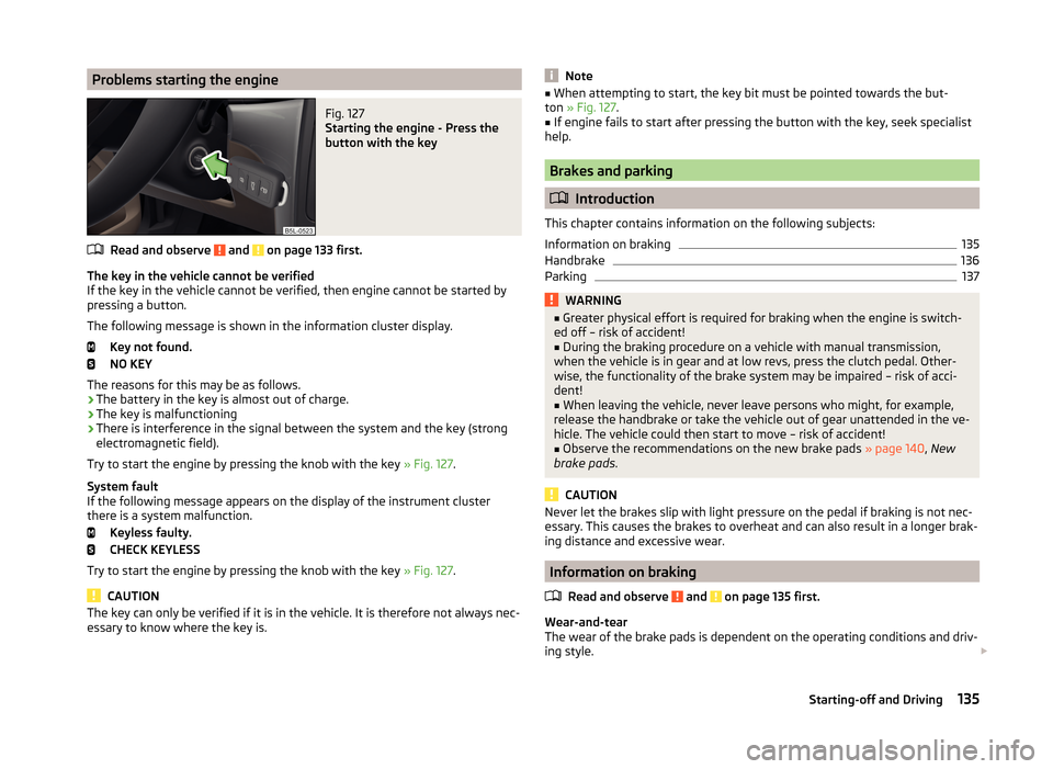
Starting the engine - Press the
button with the key
Read and observe and on page 133 first.
The key in the vehicle cannot be verified
If the key in the vehicle cannot be verified, then engine cannot be started by pressing a button.
The following message is shown in the information cluster display. Key not found.
NO KEY
The reasons for this may be as follows.
› The battery in the key is almost out of charge.
› The key is malfunctioning
› There is interference in the signal between the system and the key (strong
electromagnetic field).
Try to start the engine by pressing the knob with the key » Fig. 127.
System fault
If the following message appears on the display of the instrument cluster
there is a system malfunction.
Keyless faulty.
CHECK KEYLESS
Try to start the engine by pressing the knob with the key » Fig. 127.
CAUTION
The key can only be verified if it is in the vehicle. It is therefore not always nec-
essary to know where the key is.Note■ When attempting to start, the key bit must be pointed towards the but-
ton » Fig. 127 .■
If engine fails to start after pressing the button with the key, seek specialist
help.
Brakes and parking
Introduction
This chapter contains information on the following subjects:
Information on braking
135
Handbrake
136
Parking
137WARNING■ Greater physical effort is required for braking when the engine is switch-
ed off – risk of accident!■
During the braking procedure on a vehicle with manual transmission,
when the vehicle is in gear and at low revs, press the clutch pedal. Other-
wise, the functionality of the brake system may be impaired – risk of acci-
dent!
■
When leaving the vehicle, never leave persons who might, for example,
release the handbrake or take the vehicle out of gear unattended in the ve-
hicle. The vehicle could then start to move – risk of accident!
■
Observe the recommendations on the new brake pads » page 140, New
brake pads .
CAUTION
Never let the brakes slip with light pressure on the pedal if braking is not nec-
essary. This causes the brakes to overheat and can also result in a longer brak-
ing distance and excessive wear.
Information on braking
Read and observe
and on page 135 first.
Wear-and-tear
The wear of the brake pads is dependent on the operating conditions and driv-
ing style.
135Starting-off and Driving
Page 139 of 248
The brake pads wear more quickly if a lot of journeys are completed in towns
and over short distances or if a very sporty style of driving is adopted.
If operated under severe conditions , the thickness of the brake pads must be
checked by a specialist garage between service appointments as well.
Wet roads or road salt
The performance of the brakes can be delayed as the brake discs and brake
pads may be moist or have a coating of ice or layer of salt on them in winter.
The brakes are cleaned and dried by applying the brakes several times »
.
Corrosion
Corrosion on the brake discs and dirt on the bake pads occur if the vehicle has
been parked for a long period and if you do not make much use of the braking
system. The brakes are cleaned and dried by applying the brakes several
times »
.
Long or steep slopes
Before travelling a long distance with a steep gradient, reduce speed and shift
into the next lowest gear. As a result, the braking effect of the engine will be
used, reducing the load on the brakes. Any additional braking should be com-
pleted intermittently, not continuously.
Emergency brake display
If the brakes are applied in full and the control unit for the braking system con-
siders the situation to be dangerous for the following traffic, the brake light
flashes automatically.
After the speed was reduced below around 10 km/h or the vehicle was stop-
ped, the brake light stops flashing and the hazard warning light system
switches on. The hazard warning light system is switched off automatically af- ter accelerating or driving off again.
Faults in the brake surface
If it is found that the braking distance has suddenly become longer and that
the brake pedal can be depressed further, the brake system may be faulty.
Visit a specialist garage immediately and adjust your style of driving appropri-
ately, as you will not know the exact extent of the damage.
Low brake fluid level
An insufficient level of brake fluid may result in problems in the brake system.
The level of the brake fluid is monitored electronically » page 35,
Brake sys-
tem .
Brake booster
The brake booster increases the pressure generated with the brake pedal. The
brake booster only operates when the engine is running.WARNINGOnly apply the brakes for the purpose of drying and cleaning the brake
discs if the traffic conditions permit this. Do not place any other road users
in jeopardy.
Handbrake
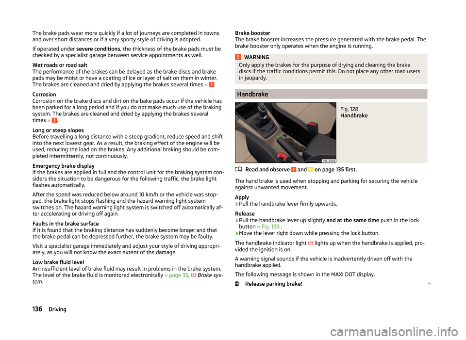
Fig. 128
Handbrake
Read and observe and on page 135 first.
The hand brake is used when stopping and parking for securing the vehicle
against unwanted movement.
Apply
›
Pull the handbrake lever firmly upwards.
Release
›
Pull the handbrake lever up slightly and at the same time push in the lock
button » Fig. 128 .
›
Move the lever right down while pressing the lock button.
The handbrake indicator light
lights up when the handbrake is applied, pro-
vided the ignition is on.
A warning signal sounds if the vehicle is inadvertently driven off with the
handbrake applied.
The following message is shown in the MAXI DOT display. Release parking brake!
136Driving
Page 145 of 248
Driving off paved roadsRead and observe
on page 141 first.
Only drive on such roads and in such terrain, which match the vehicle parame-ters » page 222 , Technical data as well as your driving skills.
The driver is always responsible for deciding whether the vehicle can handle
travelling in the given terrain.
When travelling off paved roads, we recommend activating the OFF ROAD
mode » page 144 .
WARNINGDrive particularly aware and pro-actively outside paved roads.■Always adjust your driving to the current terrain and weather conditions.
Excessive speed or incorrect driving manoeuvres can cause damage to the
vehicle and lead to serious injuries.■
Objects trapped under the floor of the vehicle can damage the fuel lines,
the brake system, the seals and other parts of the chassis. Check the un-
derside of the vehicle and remove the trapped objects.
■
Combustible objects such as dry leaves or twigs caught under the base of
the vehicle could ignite on hot vehicle parts - risk of fire!
CAUTION
■ Pay attention to the ground clearance of the vehicle! When driving over ob-
jects which are larger than the ground clearance, the chassis and its compo-
nents can get damaged.■
Drive slowly in unknown terrain and watch out for unexpected obstacles,
such as potholes, rocks, stumps, etc.
■
Check up on confusing sections of unpaved roads before travelling on them
and consider whether such travelling is possible without risk.
Assist systems
Braking and stabilisation systems
Introduction
This chapter contains information on the following subjects:
Electronic Stability Control (ESC)
143
Antilock Braking System (ABS)
143
Traction Control System (TCS)
143
Electronic Differential Lock (EDL)
143
Driver Steering Recommendation (DSR)
144
Hydraulic Brake Assist (HBA)
144
Hill Hold Control (HHC)
144
Trailer stabilisation (TSA)
144
This chapter deals with the functions of the braking and stabilisation systems,
with the error indicator referred to in chapter » page 34, Warning lights .
The braking and stabilisation systems are automatically activated each time
the ignition is switched on.
WARNING■ A lack of fuel can cause irregular engine running or cause the engine to
shut down. The brake assist systems would then fail to function – risk of
accident!■
The increased safety provided by the brake assist systems must not
tempt you to take safety risks – risk of accident!
■
Adjust the speed and driving style to the current visibility, weather, road
and traffic conditions.
142Driving
Page 158 of 248

After starting the system, the current speed is stored and the instrument clus-
ter lights up the warning light .
After the interruption in control, the stored speed can be resumed by pressing
the B
button.
Automatic control interruption
Automatic control interruption occurs if any of the following conditions are
met.
› By pressing the brake or clutch pedal.
› When one of the brake assist systems (e.g. ESC) intervenes.
› Through an airbag deployment.
WARNING■
Always deactivate the cruise control system after use to prevent the sys-
tem being switched on unintentionally.■
Control may only be resumed if the stored speed is not too high for the
current traffic conditions.
Note
During control, speed can be increased by pressing the accelerator pedal. Re-
leasing the accelerator pedal will cause the speed to drop again to the set
speed.
START-STOP
Introduction
This chapter contains information on the following subjects:
Operating conditions of the system
155
Operation in vehicles with manual gearbox
156
Operation in vehicles with automatic gearbox
156
System related automatic start-up
156
Manually deactivating/activating the system
157
Information messages
157
The START-STOP system (hereinafter referred to as the system) saves fuel and
reduces polluting emissions and CO 2 emissions by turning the engine off, e.g.
when stopping at traffic lights, and starting the engine again when moving off.
WARNING■ Never let the vehicle roll with the engine switched off.■The brake servo unit and power steering only operate if the engine is run-
ning.
Operating conditions of the system
Fig. 144
Maxi DOT display: Engine is auto-
matically switched off / automat-
ic engine cut off is not possible
Read and observe on page 155 first.
For system-dependent automatic engine shutdown
to work, the following conditions must be met.
The driver's door is closed.
The driver has fastened the seat belt.
The bonnet is closed.
The driving speed was higher than 4 km.h after the last stop.
No trailer is coupled.
Some additional conditions for the system to function correctly cannot be in-
fluenced or recognised by the driver. Therefore, the system can react differ-
ently in situations which are identical from the driver's perspective.
If after stopping the car, the message START-STOP NOT POSSIBLE appears in
the segment display or the
» Fig. 144 check mark appears in the MAXI DOT
display, then the conditions for automatic engine shutdown are not met.
Running the engine is essential for the following reasons, for example.
› The engine temperature for the proper function of the system has not yet
been reached.
› The charge state of the vehicle battery is too low.
› The current consumption is too high.
› High air-conditioning or heating capacity (high fan speed, big difference be-
tween the desired and actual interior temperature).
155Assist systems
Page 159 of 248
Note■If the vehicle remains outdoors for a long time in minus temperatures or in
direct sunlight, it can take several hours until the internal temperature of the
vehicle battery reaches a suitable temperature for proper operation of the
START STOP system.■
If the driver's seat belt is removed for more than approx. 30 seconds or the
driver's door is opened during stop mode, the engine will have to be started
manually.
■
After the manual engine start and with a manual gearbox the automatic en-
gine shutdown can take place only when a minimum distance required for the
system function has been covered.
Operation in vehicles with manual gearbox
Read and observe
on page 155 first.
In compliance with the operating conditions, automatic engine shutdown / au-
tomatic engine start takes place as described.
Automatic engine shutdown
›
Stop the vehicle.
›
Put the gear stick into Neutral.
›
Release the clutch pedal.
Automatic engine shutdown takes place, segment display shows START-STOP
ACTIVE or a check mark appears in the MAXI DOT display
» Fig. 144 on
page 155 .
Automatic engine start
›
Depress the clutch pedal.
The automatic start procedure takes place again.
Operation in vehicles with automatic gearbox
Read and observe
on page 155 first.
In compliance with the operating conditions, automatic engine shutdown / au-
tomatic engine start takes place as described.
Automatic engine shutdown
›
Bring the vehicle to a stop and depress the brake pedal.
Automatic engine shutdown takes place, segment display shows START-STOP
ACTIVE or a check mark appears in the MAXI DOT display » Fig. 144 on
page 155 .
Automatic engine start›
Release the brake pedal.
The automatic start procedure takes place again.
Further information on automatic transmission
The automatic engine shut down takes place when the selector lever is in po-
sitions P, D , S and N and in Tiptronic mode.
When the selector lever is in position P the engine remains shut down after
you release the brake pedal. The engine starts automatically by pressing the
gas pedal or by moving the selector lever into a different mode and releasing
the brake pedal.
If the engine is off due to the automatic and the selector lever is put to the R
position then the automatic starts the engine.
If the gear selector is moved from position R to the position D, S or N, the vehi-
cle must reach a speed of more than 10 km / h before the automatic engine
shutdown starts.
There is no automatic engine shutdown when the system detects a vehicle
moving due to a large steering angle.
No automatic engine shutdown takes place when the vehicle is moving at low
speed (e.g. during a traffic jam or when tuning) and remains stationary after
pressing the brake pedal lightly. Automatic engine shutdown takes place if you
press the brake pedal down with more force.
System related automatic start-up
Read and observe
on page 155 first.
When the engine is off, the system can automatically start the engine beforethe desired journey continues. Some possible reasons for this are:
› The vehicle begins to roll, e.g. on a slope.
› The brake pedal has been actuated several times.
› The current consumption is too high.
156Driving
Page 166 of 248
AccessoriesFig. 155
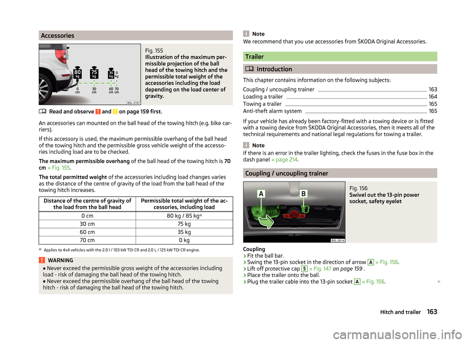
Illustration of the maximum per-
missible projection of the ball
head of the towing hitch and the
permissible total weight of the
accessories including the load
depending on the load center of
gravity.
Read and observe and on page 159 first.
An accessories can mounted on the ball head of the towing hitch (e.g. bike car-
riers).
If this accessory is used, the maximum permissible overhang of the ball head
of the towing hitch and the permissible gross vehicle weight of the accesso-
ries including load are to be checked.
The maximum permissible overhang of the ball head of the towing hitch is 70
cm » Fig. 155 .
The total permitted weight of the accessories including load changes varies
as the distance of the centre of gravity of the load from the ball head of the
towing hitch increases.
Distance of the centre of gravity of the load from the ball headPermissible total weight of the ac- cessories, including load0 cm80 kg / 85 kg a)30 cm75 kg60 cm35 kg70 cm0 kga)
Applies to 4x4 vehicles with the 2.0 l / 103 kW TDI CR and 2.0 L / 125 kW TDI CR engine.
WARNING■
Never exceed the permissible gross weight of the accessories including
load - risk of damaging the ball head of the towing hitch.■
Never exceed the permissible overhang of the ball head of the towing
hitch - risk of damaging the ball head of the towing hitch.
NoteWe recommend that you use accessories from ŠKODA Original Accessories.
Trailer
Introduction
This chapter contains information on the following subjects:
Coupling / uncoupling trainer
163
Loading a trailer
164
Towing a trailer
165
Anti-theft alarm system
165
If your vehicle has already been factory-fitted with a towing device or is fitted
with a towing device from ŠKODA Original Accessories, then it meets all of the
technical requirements and national legal regulations for towing a trailer.
Note
If there is an error in the trailer lighting, check the fuses in the fuse box in the
dash panel » page 214.
Coupling / uncoupling trainer
Fig. 156
Swivel out the 13-pin power
socket, safety eyelet
Coupling
›
Fit the ball bar.
›
Swing the 13-pin socket in the direction of arrow
A
» Fig. 156 .
›
Lift off protective cap
5
» Fig. 147 on page 159 .
›
Place the trailer onto the ball.
›
Plug the trailer cable into the 13-pin socket
A
» Fig. 156 .
163Hitch and trailer
Page 167 of 248

If the trailer that is to be towed has a 7-pin connector, you can use a suitable
adapter from ŠKODA Original Accessories to establish a connection to the elec-
tricity.›
Hook the breakaway cable of the trailer onto the safety eyelet
B
.
The breakaway cable of the trailer has to sag when mounted into the security
lock slot for all trailer positions relative to the vehicle (sharp curves, reverse
driving and the like.)
Uncoupling
›
Unhook the breakaway cable of the trailer from the safety eyelet
B
» Fig. 156 .
›
Unplug the trailer cable from the 13-pin socket.
›
Remove the trailer from the ball head.
›
Place the cap
5
» Fig. 147 on page 159 onto the ball head.
›
Grip the 13-pin socket at point
A
and swing in the opposite direction to the
arrow » Fig. 156 .
Exterior mirrors
You have to have additional exterior mirrors fitted if you are not able to see
the traffic behind the trailer with the standard rear-view mirrors. The national
legal requirements must be observed.
Headlights
The front of the vehicle may lift up when a trailer is being towed and the head-
lights may dazzle other road users.
Adjust the headlights using the headlight beam control » page 64,
Lights
and visibility 1)
.
WARNING■ Incorrect or improperly connected electrical installation can cause acci-
dents and serious injury due to electric shock.■
Work on the electrical system must only be carried out by specialist ga-
rages.
■
Never directly connect the trailer's electrical system with the electrical
connections for the tail lights or other current sources.
■
After coupling the trailer and connecting up the power socket, check the
rear lights on the trailer to ensure they are working.
WARNING (Continued)■ The handbrake on the towing vehicle must be applied when coupling and
uncoupling the trailer.■
Never use the safety eyelet for towing!
CAUTION
Incorrect or improperly connected electrical installations may cause malfunc-
tion of the entire vehicle electronics.
Loading a trailer
The vehicle/trailer combination must be balanced, whereby the maximum per-
missible drawbar load must be utilised. If the drawbar load is too low, it jeop-
ardises the performance of the vehicle/trailer combination.
Distribution of the load
Distribute the load in the trailer in such a way that heavy items are located as
close to the axle as possible. Secure the items from slipping.
The distribution of the weight is very poor if your vehicle is unladen and the
trailer is laden. Maintain a particularly low speed if you cannot avoid driving
with this combination.
Tyre pressure
Correct the tyre inflation pressure on your vehicle for a “full load” » page 191.
Towing capacity and trailer weight
The permissible trailer load must not be exceeded under any circumstan-
ces » page 222 , Technical data .
The details given in the vehicle's technical documentation always take prece-
dence over the details in the Owner's Manual.
The trailer loads specified apply only to altitudes up to 1 000 metres above
mean sea level.
The engine output falls as altitude increases, as does the vehicle's climbing
power. Therefore, for every additional 1000 m in height (or part), the maximum
permissible towed weight must be reduced by 10%.
The towed weight is made up of the actual weights of the loaded towing vehi-
cle and the loaded trailer.
1)
Applies to vehicles with bi-xenon headlights.
164Driving