stop start SKODA YETI 2014 1.G / 5L Owner's Guide
[x] Cancel search | Manufacturer: SKODA, Model Year: 2014, Model line: YETI, Model: SKODA YETI 2014 1.G / 5LPages: 248, PDF Size: 29.49 MB
Page 143 of 248
Note■It may be beneficial, for example, when travelling downhill, to use manual
shifting of gears. Shifting to a lower gear reduces the load on the brakes and
hence the wear of the brakes » page 135, Information on braking .■
When accelerating, the gearbox automatically shifts up into the higher gear
just before the maximum permissible engine speed is reached.
■
If a lower gear is selected, the gearbox does not shift down until there is no
risk of the engine overrevving.
Starting-off and driving
Read and observe
and on page 138 first.
Starting off
›
Start the engine.
›
Firmly depress and hold the brake pedal.
›
Press the lock button in the direction of
1
» Fig. 130 on page 138 and hold.
›
Move the selector lever into the desired position » page 138 and then release
the lock button.
›
Release the brake pedal and accelerate.
Stopping (while the car is moving)
›
Depress the brake pedal and bring the vehicle to a stop.
›
Keep holding the brake pedal until driving is resumed.
The selector lever position N does not have to be selected when stopping for a
short time, such as at a cross roads.
Kickdown
The kickdown function allows you to achieve the maximum acceleration of
your vehicle while driving.
When the accelerator pedal is fully depressed, the kickdown function is activa-
ted in any forward driving mode.
The gearbox shifts down one or more gears depending on the vehicle speed
and engine speed, and the vehicle accelerates.
The gearbox does not shift up into the highest gear until the engine has
reached its maximum revolutions for this gear range.
WARNINGRapid acceleration, particularly on slippery roads, can lead to loss of control
of the vehicle – risk of accident!Running in and economical driving
Introduction
This chapter contains information on the following subjects:
Driving in
140
Tips for economical driving
140
The fuel consumption, degree of pollution and vehicle wear depend on driving
style, road condition, weather conditions and the like.
Driving in
Driving in the engine
The engine has to be run in during the first 1 500 kilometres. During this peri-
od, the driving style decides on the quality of the driving-in process.
During the first 1 000 km we recommend not driving faster than 3/4 of the
maximum permissible engine speed, not to drive at full throttle and to dis-
pense with the trailer.
In the area of 1,000 to 1,500 kilometres the engine load can be increased up
to the maximum permitted engine speed.
New tyres
New tyres must firstly be “run in”, as they do not offer optimal grip at first.
Therefore, drive especially carefully for the first 500 km or so.
New brake pads
New brake pads have to first “grind in” because these do not initially have the
best possible braking effect.
Therefore, drive especially carefully for the first 200 km or so.
Tips for economical driving
To achieve the lowest possible fuel consumption, the following instructions
must be observed.
Looking ahead when driving
Avoid unnecessary acceleration and braking.
Switch in an energy saving and timely manner Observe the recommended gear » page 43.
140Driving
Page 144 of 248
Avoid full throttle and high speeds
Fuel consumption will be halved if only three-quarters of the possible top
speed of your vehicle is used.
Reducing idling
When the engine is switched off, such as when waiting in a traffic jam, the fuel economy is already greater after 30 - 40 s than the fuel quantity which is re-
quired for engine re-start.
Avoid short distances
When driving a short distance of less than about 4 km, the engine cannot
reach its operating temperature. As long as the engine has not reached oper-
ating temperature, the fuel consumption is significantly higher than with the
engine hot.
Pay attention to the correct tyre inflation pressure being maintained
Further information » page 191.
Avoid unnecessary ballast
Per 100 kg of weight, consumption increases by about 1 l/100 km. At a speed of
100 - 120 km/h, a vehicle fitted with a roof rack cross member without a load
will use about 10 % more fuel than normal due to the increased aerodynamic
drag.
Saving electricity
Electrical consumers (e.g. seat heating, air conditioning and the like) only turn
on for as long as necessary.
Driving through water and driving off of made-up roads
Introduction
This chapter contains information on the following subjects:
Driving through water
141
Driving off paved roads
142WARNINGImmediately after driving through water, mud, slush and the like, braking
effectiveness will be temporarily impaired » page 135, Information on brak-
ing . For this reason, sudden and violent braking manoeuvres are to be
avoided - there is a risk of accident!Driving through waterFig. 132
Maximum permissible water lev-
el when driving through water
Read and observe on page 141 first.
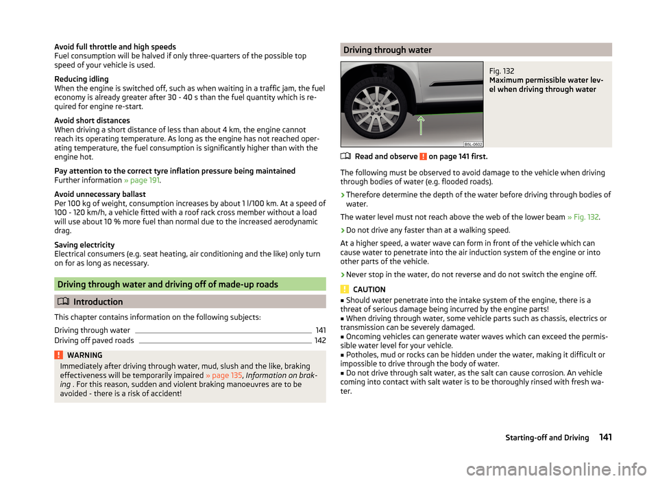
The following must be observed to avoid damage to the vehicle when driving through bodies of water (e.g. flooded roads).
›
Therefore determine the depth of the water before driving through bodies of
water.
The water level must not reach above the web of the lower beam » Fig. 132.
›
Do not drive any faster than at a walking speed.
At a higher speed, a water wave can form in front of the vehicle which can
cause water to penetrate into the air induction system of the engine or into
other parts of the vehicle.
›
Never stop in the water, do not reverse and do not switch the engine off.
CAUTION
■ Should water penetrate into the intake system of the engine, there is a
threat of serious damage being incurred by the engine parts!■
When driving through water, some vehicle parts such as chassis, electrics or
transmission can be severely damaged.
■
Oncoming vehicles can generate water waves which can exceed the permis-
sible water level for your vehicle.
■
Potholes, mud or rocks can be hidden under the water, making it difficult or
impossible to drive through the body of water.
■
Do not drive through salt water, as the salt can cause corrosion. An vehicle
coming into contact with salt water is to be thoroughly rinsed with fresh wa-
ter.
141Starting-off and Driving
Page 155 of 248
If suitable parking space is found, its parameters are stored until another suit-
able parking space has been found or until a distance of 10 m had been driven
after finding the parking space.
If the driver changes the parking mode while searching for a parking space, the
symbol button must be pressed again.
Note
If the symbol
(km / h) is shown in the display , the vehicle speed should be
reduced below 40 km / hr (parallel parking) or below 20 km / hr (Transverse
parking) .
Parking
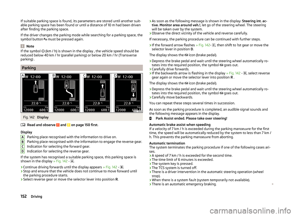
Fig. 142
Display
Read and observe
and on page 150 first.
Display Parking place recognised with the information to drive on.
Parking place recognised with the information to engage the reverse gear.
Indication for selecting the forward gear.
Indication for selecting the reverse gear.
If the system has recognised a suitable parking space, this parking space is
shown in the display » Fig. 142 -
.
›
Continue driving forwards until the display appears
» Fig. 142 -
.
›
Stop and ensure that the vehicle does not continue to move forward until
the parking procedure starts.
›
Select reverse gear or move the selector lever into position R.
ABCD› As soon as the following message is shown in the display:
Steering int. ac-
tive. Monitor area around veh.! , let go of the steering wheel. The steering
will be taken over by the system.›
Observe the direct vicinity of the vehicle and reverse carefully.
If necessary, the parking procedure can be continued with further steps.
›
If the forward arrow flashes » Fig. 142-
, then shift to 1st gear or move the
selector lever in position D.
The display shows the
icon (brake pedal).
›
Depress the brake pedal and wait until the steering wheel automatically ro-
tates into the required position, the symbol
goes out.
›
Carefully drive forwards.
›
If the backwards arrow is flashing in the display » Fig. 142 -
, select reverse
gear again or move the selector lever into position R .
The display shows the icon (brake pedal).
›
Depress the brake pedal and wait until the steering wheel automatically ro-
tates into the required position, the symbol goes out.
›
Carefully move backwards.
You can repeat these steps several times in succession.
As soon as the parking procedure is completed, an audible signal sounds and
the following message appears in the display.
Park Assist ended. Please take over steering!
Automatic brake assist when speeding
If a velocity of 7 km / h is exceeded during the parking manoeuvre for the first
time, the speed will be automatically reduced by the system to less than 7 km /
h. This prevents the parking manoeuvre from aborting.
Automatic termination
The system terminates the parking procedure if one of the following cases ari-
ses.
› A speed of 7 km / h is exceeded for the second time.
› The time limit of 6 minutes is exceeded.
› The system key is pressed.
› The TCS system is turned off.
› There is a driver intervention in the automatic steering operation (wheel
stop).
› When there is a system fault (system temporarily not available).
› There is an automatic emergency braking.
152Driving
Page 158 of 248

After starting the system, the current speed is stored and the instrument clus-
ter lights up the warning light .
After the interruption in control, the stored speed can be resumed by pressing
the B
button.
Automatic control interruption
Automatic control interruption occurs if any of the following conditions are
met.
› By pressing the brake or clutch pedal.
› When one of the brake assist systems (e.g. ESC) intervenes.
› Through an airbag deployment.
WARNING■
Always deactivate the cruise control system after use to prevent the sys-
tem being switched on unintentionally.■
Control may only be resumed if the stored speed is not too high for the
current traffic conditions.
Note
During control, speed can be increased by pressing the accelerator pedal. Re-
leasing the accelerator pedal will cause the speed to drop again to the set
speed.
START-STOP
Introduction
This chapter contains information on the following subjects:
Operating conditions of the system
155
Operation in vehicles with manual gearbox
156
Operation in vehicles with automatic gearbox
156
System related automatic start-up
156
Manually deactivating/activating the system
157
Information messages
157
The START-STOP system (hereinafter referred to as the system) saves fuel and
reduces polluting emissions and CO 2 emissions by turning the engine off, e.g.
when stopping at traffic lights, and starting the engine again when moving off.
WARNING■ Never let the vehicle roll with the engine switched off.■The brake servo unit and power steering only operate if the engine is run-
ning.
Operating conditions of the system
Fig. 144
Maxi DOT display: Engine is auto-
matically switched off / automat-
ic engine cut off is not possible
Read and observe on page 155 first.
For system-dependent automatic engine shutdown
to work, the following conditions must be met.
The driver's door is closed.
The driver has fastened the seat belt.
The bonnet is closed.
The driving speed was higher than 4 km.h after the last stop.
No trailer is coupled.
Some additional conditions for the system to function correctly cannot be in-
fluenced or recognised by the driver. Therefore, the system can react differ-
ently in situations which are identical from the driver's perspective.
If after stopping the car, the message START-STOP NOT POSSIBLE appears in
the segment display or the
» Fig. 144 check mark appears in the MAXI DOT
display, then the conditions for automatic engine shutdown are not met.
Running the engine is essential for the following reasons, for example.
› The engine temperature for the proper function of the system has not yet
been reached.
› The charge state of the vehicle battery is too low.
› The current consumption is too high.
› High air-conditioning or heating capacity (high fan speed, big difference be-
tween the desired and actual interior temperature).
155Assist systems
Page 159 of 248
Note■If the vehicle remains outdoors for a long time in minus temperatures or in
direct sunlight, it can take several hours until the internal temperature of the
vehicle battery reaches a suitable temperature for proper operation of the
START STOP system.■
If the driver's seat belt is removed for more than approx. 30 seconds or the
driver's door is opened during stop mode, the engine will have to be started
manually.
■
After the manual engine start and with a manual gearbox the automatic en-
gine shutdown can take place only when a minimum distance required for the
system function has been covered.
Operation in vehicles with manual gearbox
Read and observe
on page 155 first.
In compliance with the operating conditions, automatic engine shutdown / au-
tomatic engine start takes place as described.
Automatic engine shutdown
›
Stop the vehicle.
›
Put the gear stick into Neutral.
›
Release the clutch pedal.
Automatic engine shutdown takes place, segment display shows START-STOP
ACTIVE or a check mark appears in the MAXI DOT display
» Fig. 144 on
page 155 .
Automatic engine start
›
Depress the clutch pedal.
The automatic start procedure takes place again.
Operation in vehicles with automatic gearbox
Read and observe
on page 155 first.
In compliance with the operating conditions, automatic engine shutdown / au-
tomatic engine start takes place as described.
Automatic engine shutdown
›
Bring the vehicle to a stop and depress the brake pedal.
Automatic engine shutdown takes place, segment display shows START-STOP
ACTIVE or a check mark appears in the MAXI DOT display » Fig. 144 on
page 155 .
Automatic engine start›
Release the brake pedal.
The automatic start procedure takes place again.
Further information on automatic transmission
The automatic engine shut down takes place when the selector lever is in po-
sitions P, D , S and N and in Tiptronic mode.
When the selector lever is in position P the engine remains shut down after
you release the brake pedal. The engine starts automatically by pressing the
gas pedal or by moving the selector lever into a different mode and releasing
the brake pedal.
If the engine is off due to the automatic and the selector lever is put to the R
position then the automatic starts the engine.
If the gear selector is moved from position R to the position D, S or N, the vehi-
cle must reach a speed of more than 10 km / h before the automatic engine
shutdown starts.
There is no automatic engine shutdown when the system detects a vehicle
moving due to a large steering angle.
No automatic engine shutdown takes place when the vehicle is moving at low
speed (e.g. during a traffic jam or when tuning) and remains stationary after
pressing the brake pedal lightly. Automatic engine shutdown takes place if you
press the brake pedal down with more force.
System related automatic start-up
Read and observe
on page 155 first.
When the engine is off, the system can automatically start the engine beforethe desired journey continues. Some possible reasons for this are:
› The vehicle begins to roll, e.g. on a slope.
› The brake pedal has been actuated several times.
› The current consumption is too high.
156Driving
Page 160 of 248

Manually deactivating/activating the systemFig. 145
Button for the START-STOP sys-
tem
Read and observe on page 155 first.
Deactivating/activating
›
Press the symbol button
» Fig. 145 .
When start-stop mode is deactivated, the indicator light in the button lights
up.
Note
If the system is deactivated when the engine is turned off automatically, then
the automatic start process takes place.
Information messages
Read and observe
on page 155 first.
The messages and information are indicated in the instrument cluster display. Start engine manually!
START MANUALLY
One of the conditions for automatic engine start is not satisfied or the driver's
seat belt is not fastened. The engine must be started manually.
On vehicles with the system KESSY the ignition is turned off by the first press
of the start button, only after pressing for the second time is the start process
initiated.
Error: Start-Stop system
ERROR START-STOP
A system error is present. Seek help from a specialist garage.
Fatigue detection (break recommendation)
Introduction
This chapter contains information on the following subjects:
Function
157
Information messages
158
The fatigue detection system (hereinafter referred to only as system) recom-
mends the driver taking a break from driving when, because of the driver's
steering behaviour, driver fatigue can be detected.
WARNING■ For the driving ability is always the driver's responsibility. Never drive if
you feel tired.■
The system may not detect all cases where a break is needed.
■
Therefore, take regular, sufficient breaks during long trips.
■
There will be no system warning during the so-called micro-sleep.
Note
■ In some situations, the system may evaluate the driving incorrectly and thus
mistakenly recommend a break (e.g. sporty driving, adverse weather condi-
tions or poor road conditions).■
The system is designed primarily for use on motorways.
Function
Read and observe
on page 157 first.
From the start of the journey, the system evaluates steering behaviour. If,
while driving, there have been changes in the steering behaviours that are
evaluated by the system as indicating possible fatigue, a break recommenda-
tion is issued.
The system evaluates steering behaviour and recommends a break at speeds
of 65-200 km / h.
The system detects a break from driving when one of the following condi-
tions is met.
› The vehicle is stopped and the ignition switched off.
› The vehicle is stopped, the seat belt removed and the driver's door opened.
› The vehicle is stopped for more than 15 minutes.
157Assist systems
Page 168 of 248
The trailer and drawbar load information on the type plate of the towing de-
vice is merely a test value for the towing device. The vehicle-specific values
are detailed in the vehicle documents.WARNING■ Never exceed the maximum permissible axle and drawbar load or the per-
missible weight of the trailer - risk of accident!■
Sliding cargo can significantly adversely affect stability and driving safety
- risk of accident!
Towing a trailer
Driving speed
For safety reasons, do not drive faster than 80 km/h when towing a trailer.
Immediately reduce your speed as soon as even the slightest swaying of the
trailer is detected. Never attempt to stop the trailer from “swaying” by acceler-
ating.
Brakes
Apply the brakes in good time! If the trailer is fitted with a trailer brake, apply
the brakes gently at first, then brake firmly. This will avoid brake jolts resulting
from the trailer wheels locking.
On downhill sections shift down a gear in good time to also use the engine as
a brake.
Engine overheating
If the needle for the coolant temperature gauge moves into the right-hand
area or the red area of the scale, the speed must be reduced immediately.
Stop and switch off the engine if the indicator light in the instrument cluster
starts to flash.
The following guidelines must be observed » page 36,
Coolant
.
The coolant temperature can be reduced by switching on the heating.
WARNING■ Always drive particularly carefully with the trailer.■Adapt your speed to the conditions of the road surface and to the traffic
situation.CAUTIONIf you tow a trailer frequently, you should also have your vehicle inspected be-
tween service intervals.
Anti-theft alarm system
If the vehicle is locked, the alarm is activated when the electrical connection to
the trailer is interrupted.
Always switch off the anti-theft alarm system before a trailer is coupled or un-
coupled » page 56 .
Conditions for including a trailer in the anti-theft alarm system. The vehicle is factory-fitted with an anti-theft alarm system and towing
device.
The trailer is electrically connected to the towing vehicle via the trailer
socket.
The electrical system of the vehicle and trailer is functional.
The vehicle is locked with the vehicle key and the anti-theft alarm system
is activated.
CAUTION
For technical reasons, trailers with rear LED lights cannot be connected to the
anti-theft alarm system.165Hitch and trailer
Page 192 of 248
Air bubbles can influence the colour of the indicator. For this reason carefully
knock on the indicator before carrying out the check.
› Black colour - electrolyte level is correct.
› Colourless or light yellow colour - electrolyte level too low, the battery must
be replaced.
Vehicles with a START-STOP system are fitted with a battery control unit for
checking the energy level for recurring engine start.
We recommend that you have the acid level checked regularly by a specialist garage, especially in the following cases.
› High external temperatures.
› Longer day trips.
› After each charge.
Winter time
The vehicle battery only has a proportion of the starting power in lower tem-
peratures. A discharged vehicle battery may already freeze at temperatures
just below 0 °C .
We therefore recommend that you have the battery checked and, if necessary,
recharged by a specialist garage before the start of the winter.
Note
■ The battery acid level is also checked regularly by a specialist garage as part
of the inspection service.■
For technical reasons, on vehicles with the description “AGM”, the electrolyte
level cannot be checked.
Charging
Read and observe
and on page 187 first.
A properly charged vehicle battery is essential for reliably starting the engine.A charging operation can be performed if the following conditions are satis-
fied.
The engine is turned off.
The ignition is switched off.
All consumers are turned off.
The bonnet is open.
“Fast charging” with high currents
›
Disconnect both battery cables (first of all “negative”, then “positive”).
› Attach the terminal clamps of the charger to the battery terminals (red =
“positive”, black = “negative”).›
Plug the mains cable of the charger into the power socket and switch on the
device.
›
After charging has been successful: Switch off the charger and remove the
mains cable from the power socket.
›
Only then disconnect the charger's terminal clamps.
›
Reconnect the cables to the battery (first “positive”, then “negative”).
Charging with low voltages
It is not necessary to disconnect the cables from the battery if you recharge
the vehicle battery, for example from a mini-charger.
Refer to the instructions of the charger manufacturer .
A charging current of 0.1 multiple of the total vehicle battery capacity (or low-
er) must be used until full charging is achieved.
The vent plugs of the vehicle battery should not be opened for charging.
WARNING■ When you charge a battery, hydrogen is released, and a highly explosive
gas mixture is also produced. An explosion can be caused through sparkling
over during unclamping or loosening of the cable plug while the ignition is
on.■
Creating a bridge between the poles on the battery (e.g. with metal ob-
jects - cables) creates a short circuit - risk of damage to the battery, explo-
sion and burning of the battery, jets of acid spurting out.
■
Avoid creating sparks when working with cables and electrical devices.
Strong sparking represents a risk of injury.
■
Before carrying out any work on the electrical system, switch off the en-
gine, the ignition and all electrical consumers and disconnect the negative
terminal
.
■
“Quick-charging” the vehicle battery is dangerous and requires a special
charger and specialist knowledge.
■
We therefore recommend that vehicle batteries be “rapidly charged” by a
specialist garage.
CAUTION
On vehicles with the START / STOP system or additional heating (auxiliary
heating), do not connect the pole terminal of the charger directly to the nega-
tive terminal of the vehicle battery but only to the engine earth » page 206.189Inspecting and replenishing
Page 206 of 248
WARNINGNotes for vehicle lifting■Choose a flat and firm surface for jacking the vehicle.■
If the wheel has to be changed on a slope, first of all block the opposite
wheel with a stone or similar object to prevent the vehicle from unexpect-
edly rolling away.
■
Secure the base plate of the lifting jack with suitable means to prevent
possible moving. A soft and slippery ground under the base plate may move
the lifting jack, causing the vehicle to fall down. It is therefore always nec-
essary to place the lifting jack on a solid surface or use a wide and stable
base. Use a non-slip base (e.g. a rubber foot mat) if the surface is smooth,
such as cobbled stones, tiled floor, etc.
■
Only attach the lifting jack to the attachment points provided for this pur-
pose.
■
Always raise the vehicle with the doors closed.
■
Never position any body parts, such as arms or legs under the vehicle,
while the vehicle is raised with a lifting jack.
■
When the vehicle is raised, never start the engine.
CAUTION
It is important to ensure that the jack is correctly attached to the web of the
lower fork leg - risk of damage to the vehicle.
Anti-theft wheel bolts
Fig. 177
Principle sketch: Anti-theft
wheel bolt with adapter
The anti-theft wheel bolts protect the wheels from theft. These can only be
loosened or tightened with the use of adapter
B
» Fig. 177 .
›
Remove the full wheel trim or the caps of the wheel bolts.
›
Insert adapter
B
» Fig. 177 with the toothed side all the way into the inner
teeth in the head of the anti-theft wheel bolts
A
.
› Push the wheel wrench onto the adapter B up to the stop.›Loosen or tighten the wheel bolt
» page 202.›
Remove the adapter.
›
Replace the wheel trim or the caps.
To be equipped for a possible wheel change, the adapter for the anti-theft
wheel bolts must always be kept in the vehicle. The adapter is stowed in the
tool kit.
Note
■ Note the code number which is embossed both on the adapter and also on
the end of each anti-theft wheel bolt. This number can be used to purchase a
replacement adapter from ŠKODA Original Parts if necessary.■
The anti-theft wheel bolt set and adapter can be purchased from a ŠKODA
Partner.
■
The position of the anti-theft wheel bolt is marked on the back of the wheel
cover with every ŠKODA supplied original equipment hub cap or directly at the
factors. When using an anti-theft wheel bolt, make sure that this has been fit-
ted according to the position marked on the back of the wheel cover position.
Puncture repair kit
Introduction
This chapter contains information on the following subjects:
Components of the puncture repair kits
204
General information
204
Preparations for using the breakdown kit
205
Sealing and inflating the tyre
205
Notes for driving with repaired tyres
205
Use the breakdown kit to reliably repair tyre damage caused by foreign bodies
or a puncture with diameters up to approx. 4 mm.
Performing a repair with the breakdown kit not at all intended to replace a
permanent repair on the tyre. Its purpose is to get you to the nearest specialist
garage.
The wheel must not be removed during repair.
Do not remove foreign bodies , e.g. screws or nails, from the tyre!
203Emergency equipment and self-help
Page 209 of 248
›Continue driving carefully to the nearest specialist garage at a maximum
speed of 80 km/h (50 mph).WARNING■ A tyre filled with sealant has the same driving characteristics as a stand-
ard tyre.■
Do not drive faster than 80 km/h (50 mph).
■
Avoid accelerating at full throttle, sharp braking and fast cornering.
Jump-starting
Introduction
This chapter contains information on the following subjects:
Jump-starting using the battery from another vehicle
206
The battery of another vehicle can be used to jump-start your vehicle if the en-
gine will not start because the battery is flat.
WARNING■ Pay attention to the warning instructions relating to working in the en-
gine compartment » page 180.■
A discharged vehicle battery may already freeze at temperatures just be-
low 0 °C. If the battery is frozen, do not carry out a jump start with the bat-
tery of another vehicle – risk of explosion!
■
Keep any sources of ignition (naked flame, smouldering cigarettes, etc.)
away from the battery – risk of explosion!
■
Never jump-start vehicle batteries with an electrolyte level that is too low
– risk of explosion and caustic burns.
■
The vent screws of the battery cells must be tightened firmly.
Note
We recommend you buy jump-start cables from a car battery specialist.Jump-starting using the battery from another vehicleFig. 179
Jump-starting: A – flat battery, B
– battery providing current
Fig. 180
Engine earth: START-STOP sys-
tem
Read and observe on page 206 first.
The starting process using the battery of another vehicle requires the use of
jumper cables.
The jump-start cables must be attached in the following sequence.
›
Attach clamp
1
to the positive terminal of the discharged battery
A
» Fig. 179 .
›
Attach clamp
2
to the positive terminal of the battery supplying power
B
.
›
Attach clamp
3
to the negative terminal of the battery supplying power
B
.
›
Attach the clamp
4
to a solid metal part which is connected firmly to the en-
gine block or to the engine block itself.
The jump-start cable must be connected to the engine earthing point only on
vehicles with the START-STOP system » Fig. 180.
Starting engine
›
Start the engine on the vehicle providing the power and allow it to idle.
›
Start the engine of the vehicle with the discharged battery.
206Do-it-yourself