fuel type SKODA YETI 2014 1.G / 5L Owner's Manual
[x] Cancel search | Manufacturer: SKODA, Model Year: 2014, Model line: YETI, Model: SKODA YETI 2014 1.G / 5LPages: 248, PDF Size: 29.49 MB
Page 10 of 248
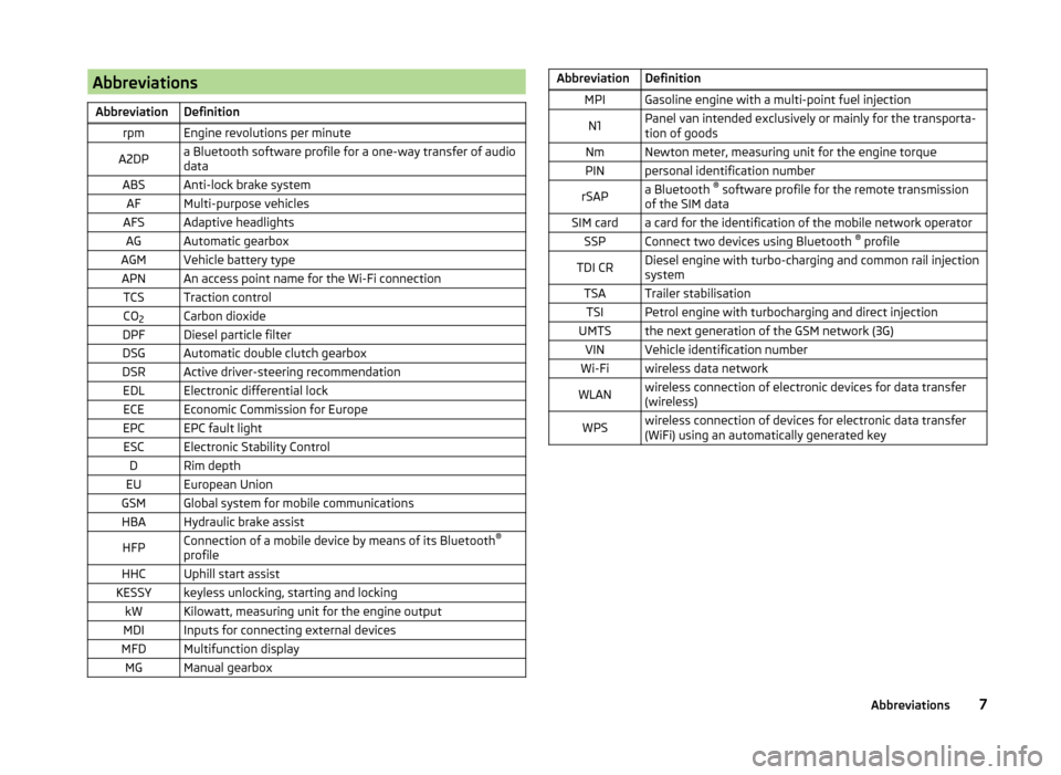
AbbreviationsAbbreviationDefinitionrpmEngine revolutions per minuteA2DPa Bluetooth software profile for a one-way transfer of audio
dataABSAnti-lock brake systemAFMulti-purpose vehiclesAFSAdaptive headlightsAGAutomatic gearboxAGMVehicle battery typeAPNAn access point name for the Wi-Fi connectionTCSTraction controlCO 2Carbon dioxideDPFDiesel particle filterDSGAutomatic double clutch gearboxDSRActive driver-steering recommendationEDLElectronic differential lockECEEconomic Commission for EuropeEPCEPC fault lightESCElectronic Stability ControlDRim depthEUEuropean UnionGSMGlobal system for mobile communicationsHBAHydraulic brake assistHFPConnection of a mobile device by means of its Bluetooth ®
profileHHCUphill start assistKESSYkeyless unlocking, starting and lockingkWKilowatt, measuring unit for the engine outputMDIInputs for connecting external devicesMFDMultifunction displayMGManual gearboxAbbreviationDefinitionMPIGasoline engine with a multi-point fuel injectionN1Panel van intended exclusively or mainly for the transporta-
tion of goodsNmNewton meter, measuring unit for the engine torquePINpersonal identification numberrSAPa Bluetooth ®
software profile for the remote transmission
of the SIM dataSIM carda card for the identification of the mobile network operatorSSPConnect two devices using Bluetooth ®
profileTDI CRDiesel engine with turbo-charging and common rail injection
systemTSATrailer stabilisationTSIPetrol engine with turbocharging and direct injectionUMTSthe next generation of the GSM network (3G)VINVehicle identification numberWi-Fiwireless data networkWLANwireless connection of electronic devices for data transfer
(wireless)WPSwireless connection of devices for electronic data transfer
(WiFi) using an automatically generated key7Abbreviations
Page 20 of 248
System descriptionRead and observe
on page 16 first.
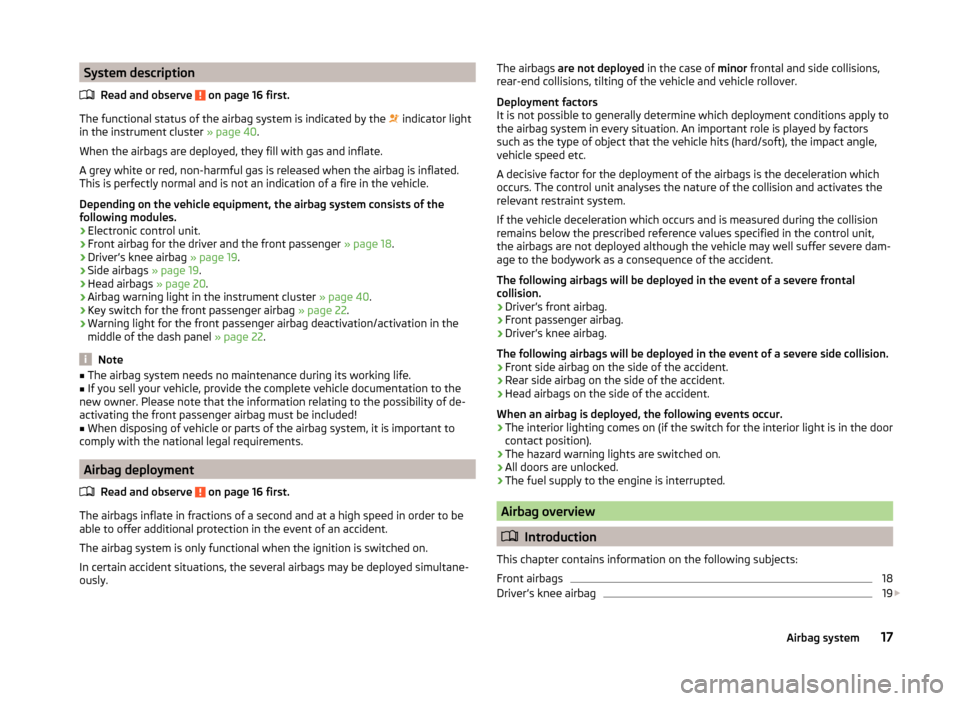
The functional status of the airbag system is indicated by the
indicator light
in the instrument cluster » page 40.
When the airbags are deployed, they fill with gas and inflate.
A grey white or red, non-harmful gas is released when the airbag is inflated.
This is perfectly normal and is not an indication of a fire in the vehicle.
Depending on the vehicle equipment, the airbag system consists of the
following modules.
› Electronic control unit.
› Front airbag for the driver and the front passenger
» page 18.
› Driver’s knee airbag
» page 19.
› Side airbags
» page 19.
› Head airbags
» page 20.
› Airbag warning light in the instrument cluster
» page 40.
› Key switch for the front passenger airbag
» page 22.
› Warning light for the front passenger airbag deactivation/activation in the
middle of the dash panel » page 22.
Note
■
The airbag system needs no maintenance during its working life.■If you sell your vehicle, provide the complete vehicle documentation to the
new owner. Please note that the information relating to the possibility of de-
activating the front passenger airbag must be included!■
When disposing of vehicle or parts of the airbag system, it is important to
comply with the national legal requirements.
Airbag deployment
Read and observe
on page 16 first.
The airbags inflate in fractions of a second and at a high speed in order to beable to offer additional protection in the event of an accident.
The airbag system is only functional when the ignition is switched on.
In certain accident situations, the several airbags may be deployed simultane-
ously.
The airbags are not deployed in the case of minor frontal and side collisions,
rear-end collisions, tilting of the vehicle and vehicle rollover.
Deployment factors
It is not possible to generally determine which deployment conditions apply to
the airbag system in every situation. An important role is played by factors
such as the type of object that the vehicle hits (hard/soft), the impact angle,
vehicle speed etc.
A decisive factor for the deployment of the airbags is the deceleration which
occurs. The control unit analyses the nature of the collision and activates the
relevant restraint system.
If the vehicle deceleration which occurs and is measured during the collision
remains below the prescribed reference values specified in the control unit,
the airbags are not deployed although the vehicle may well suffer severe dam-
age to the bodywork as a consequence of the accident.
The following airbags will be deployed in the event of a severe frontal
collision.
› Driver’s front airbag.
› Front passenger airbag.
› Driver’s knee airbag.
The following airbags will be deployed in the event of a severe side collision.
› Front side airbag on the side of the accident.
› Rear side airbag on the side of the accident.
› Head airbags on the side of the accident.
When an airbag is deployed, the following events occur.
› The interior lighting comes on (if the switch for the interior light is in the door
contact position).
› The hazard warning lights are switched on.
› All doors are unlocked.
› The fuel supply to the engine is interrupted.
Airbag overview
Introduction
This chapter contains information on the following subjects:
Front airbags
18
Driver’s knee airbag
19
17Airbag system
Page 35 of 248

DisplayFig. 25
Display types
Read and observe on page 30 first.
Display types » Fig. 25
MAXI DOT display.
Segment display
The following information will be displayed.
› Distance travelled
» page 33
› Time
» page 33
› Information system data
» page 42
› Service interval display data
» page 49
CAUTION
Pull out the ignition key if coming in contact with the display (e.g. when clean-
ing) to prevent any possible damage. On vehicles with the KESSY system,
switch off the ignition and open the driver's door.Fuel gaugeFig. 26
Fuel gauge
Read and observe on page 30 first.
The display » Fig. 26 provides information on the fuel supply in the container.
The display only works if the ignition is switched on.
The fuel tank has a capacity of about 55 litres or 60 litres 1)
.
If the amount of fuel reaches the reserve area (the pointer reaches the red
scale range), the indicator symbol is illuminated
» page 40 .
CAUTION
Never drive until the fuel tank is completely empty! The irregular supply of fuel
can cause misfiring. This can result in considerable damage to parts of the en-
gine and the exhaust system.
Note
After filling up, it can occur that during dynamic driving (e.g. numerous curves,
braking, driving downhill and climbing a steep hill) the fuel gauge indicates ap-
prox. a fraction less. When stopping or during less dynamic driving, the fuel
gauge displays the correct fuel level again. This is not a fault.1)
Valid for Yeti 4x4.
32Using the system
Page 180 of 248
Inspecting and replenishing
Fuel
Introduction
This chapter contains information on the following subjects:
Refuelling
177
Lead-free petrol
178
Diesel fuel
179
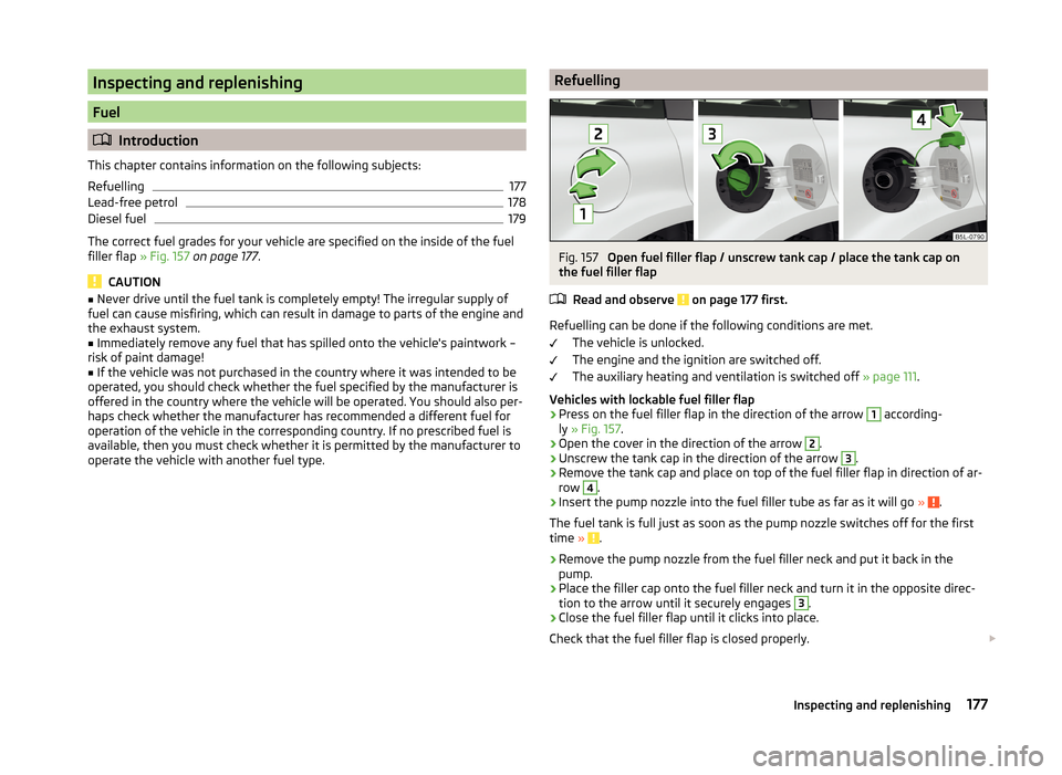
The correct fuel grades for your vehicle are specified on the inside of the fuel
filler flap » Fig. 157 on page 177 .
CAUTION
■
Never drive until the fuel tank is completely empty! The irregular supply of
fuel can cause misfiring, which can result in damage to parts of the engine and
the exhaust system.■
Immediately remove any fuel that has spilled onto the vehicle's paintwork –
risk of paint damage!
■
If the vehicle was not purchased in the country where it was intended to be
operated, you should check whether the fuel specified by the manufacturer is
offered in the country where the vehicle will be operated. You should also per-
haps check whether the manufacturer has recommended a different fuel for
operation of the vehicle in the corresponding country. If no prescribed fuel is
available, then you must check whether it is permitted by the manufacturer to
operate the vehicle with another fuel type.
RefuellingFig. 157
Open fuel filler flap / unscrew tank cap / place the tank cap on
the fuel filler flap
Read and observe
on page 177 first.
Refuelling can be done if the following conditions are met. The vehicle is unlocked.
The engine and the ignition are switched off.
The auxiliary heating and ventilation is switched off » page 111.
Vehicles with lockable fuel filler flap
›
Press on the fuel filler flap in the direction of the arrow
1
according-
ly » Fig. 157 .
›
Open the cover in the direction of the arrow
2
.
›
Unscrew the tank cap in the direction of the arrow
3
.
›
Remove the tank cap and place on top of the fuel filler flap in direction of ar-
row
4
.
›
Insert the pump nozzle into the fuel filler tube as far as it will go » .
The fuel tank is full just as soon as the pump nozzle switches off for the first
time »
.
›
Remove the pump nozzle from the fuel filler neck and put it back in the
pump.
›
Place the filler cap onto the fuel filler neck and turn it in the opposite direc-
tion to the arrow until it securely engages
3
.
›
Close the fuel filler flap until it clicks into place.
Check that the fuel filler flap is closed properly.
177Inspecting and replenishing
Page 196 of 248
Replacement of wheels
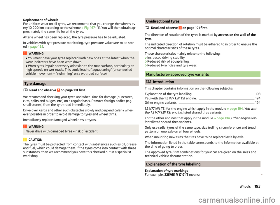
For uniform wear on all tyres, we recommend that you change the wheels ev-
ery 10 000 km according to the scheme » Fig. 167-
. You will then obtain ap-
proximately the same life for all the tyres.
After a wheel has been replaced, the tyre pressure has to be adjusted.
In vehicles with tyre pressure monitoring, tyre pressure valuesare to be stor-
ed » page 158 .WARNING■
You must have your tyres replaced with new ones at the latest when the
wear indicators have been worn down.■
Worn tyres impair necessary adhesion to the road surface, particularly at
high speeds on wet roads. This could lead to “aquaplaning” (uncontrolled vehicle movement – “swimming” on a wet road surface).
Tyre damage
Read and observe
on page 191 first.
We recommend checking your tyres and wheel rims for damage (punctures,
cuts, splits and bulges, etc.) on a regular basis. Remove foreign bodies (e.g.
small stones) from the tyre tread immediately.
Drive over kerbs and other such obstacles slowly and perpendicularly wher-
ever possible in order to avoid damage to tyres and wheel trims.
Immediately replace damaged wheel rims or tyres.
WARNINGNever drive with damaged tyres – risk of accident.
CAUTION
The tyres must be protected from contact with substances such as oil, grease
and fuel, which could damage them. If the tyres come into contact with these
substances, then we recommend you have this checked out in a specialist
workshop.Unidirectional tyres
Read and observe
on page 191 first.
The direction of rotation of the tyres is marked by arrows on the wall of the
tyre .
The indicated direction of rotation must be adhered to in order to ensure the
optimal characteristics of these tyres.
These characteristics mainly relate to the following: › Increased driving stability.
› Reduced risk of aquaplaning.
› Reduced tyre noise and tyre wear.
Manufacturer-approved tyre variants
Introduction
This chapter contains information on the following subjects:
Explanation of the tyre labelling
193
Yeti with the 1.2 l/77 kW TSI engine.
194
Other engine variants
194
1.2 l/77 kW TSI for the engine which apply in the module » page 194, Yeti with
the 1.2 l/77 kW TSI engine. listed shared tires variants.
For the other engines that apply in the module » page 194, Other engine var-
iants listed shared tires variants.
Only use radial tyres of the same type, size (rolling circumference) and tread
pattern on one axle on all four wheels.
When mounting new tires the tires have to be replaced axle by axle.
The information listed in the table corresponds to the information available at the time of going to press.
The approved tyre / rim combinations for your car are given on the sales and
technical vehicle documentation.
Explanation of the tyre labelling
Explanation of tyre markings
For example, 225/65 R 17 91 T means:
193Wheels
Page 220 of 248
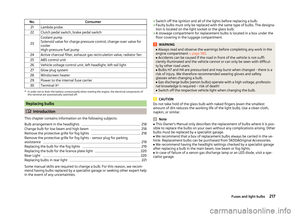
No.Consumer21Lambda probe22Clutch pedal switch, brake pedal switch
23
Coolant pump
Solenoid valve for charge pressure control, change-over valve for
cooler
High-pressure fuel pump24Active charcoal filter, exhaust gas recirculation valve, radiator fan25ABS control unit26Vehicle voltage control unit, left headlight, left tail light27Glow plug system28Windscreen heater29Power to the internal fuse carrier30Terminal X a)a)
In order not to drain the battery unnecessarily when starting the engine, the electrical components of
this terminal are automatically switched off.
Replacing bulbs
Introduction
This chapter contains information on the following subjects:
Bulb arrangement in the headlights
218
Change bulb for low beam and high beam
218
Remove the protective grille for fog lights
218
Remove the protective grille for fog lights - sensor plug for parking
assistance
219
Replacing the bulb for the fog lights
219
Replacing the bulb for the licence plate light
220
Rear Light
220
Replacing bulbs in rear light
221
Some manual skills are required to change a bulb. For this reason, we recom-
mend having bulbs replaced by a specialist garage or seeking other expert help
in the event of any uncertainties.
› Switch off the ignition and all of the lights before replacing a bulb.
› Faulty bulbs must only be replaced with the same type of bulbs. The designa-
tion is located on the light socket or the glass bulb.
› A stowage compartment for replacement bulbs is located in a box under the
floor covering in the luggage compartment.WARNING■ Always read and observe the warnings before completing any work in the
engine compartment » page 180.■
Accidents can be caused if the road in front of the vehicle is not suffi-
ciently illuminated and the vehicle cannot or can only be seen with difficul-
ty by other road users.
■
Bulbs H7 and H4 are pressurised and may burst when changed - there is a
risk of injury. We therefore recommended wearing gloves and safety
glasses when changing a bulb.
■
Gas discharge bulbs (xenon bulbs) operate with a high voltage, professio-
nal knowledge is required – risk of death!
■
Switch off the respective vehicle light when changing the bulb.
CAUTION
Do not take hold of the glass bulb with naked fingers (even the smallest
amount of dirt reduces the working life of the light bulb). Use a clean cloth,
napkin, or similar.
Note
■ This Owner's Manual only describes the replacement of bulbs where it is pos-
sible to replace the bulbs on your own without any complications arising. Other
bulbs must be replaced by a specialist garage.■
We recommend that a box of replacement bulbs always be carried in the ve-
hicle. Replacement bulbs can be purchased from ŠKODAOriginal Accessories.
■
We recommend having the headlight settings checked by a specialist garage
after replacing a bulb in the main beam, low beam or fog lights.
■
In case of failure of a xenon gas discharge lamp or an LED diode, visit a spe-
cialist garage.
217Fuses and light bulbs
Page 225 of 248
Technical data
Technical data
Vehicle data
Introduction
This chapter contains information on the following subjects:
Vehicle characteristics
222
Operating weight and payload
223
Measurement of fuel consumption and CO 2 emissions according to ECE
Regulations and EU Directives
223
Dimensions
224
angle and gradeability
225
Vehicle-specific details per engine type
226
The details given in the vehicle's technical documentation always take prece-
dence over the details in the Owner's Manual.
The listed performance values were determined without performance-reduc- ing equipment, e.g. air conditioning system.
Vehicle characteristics
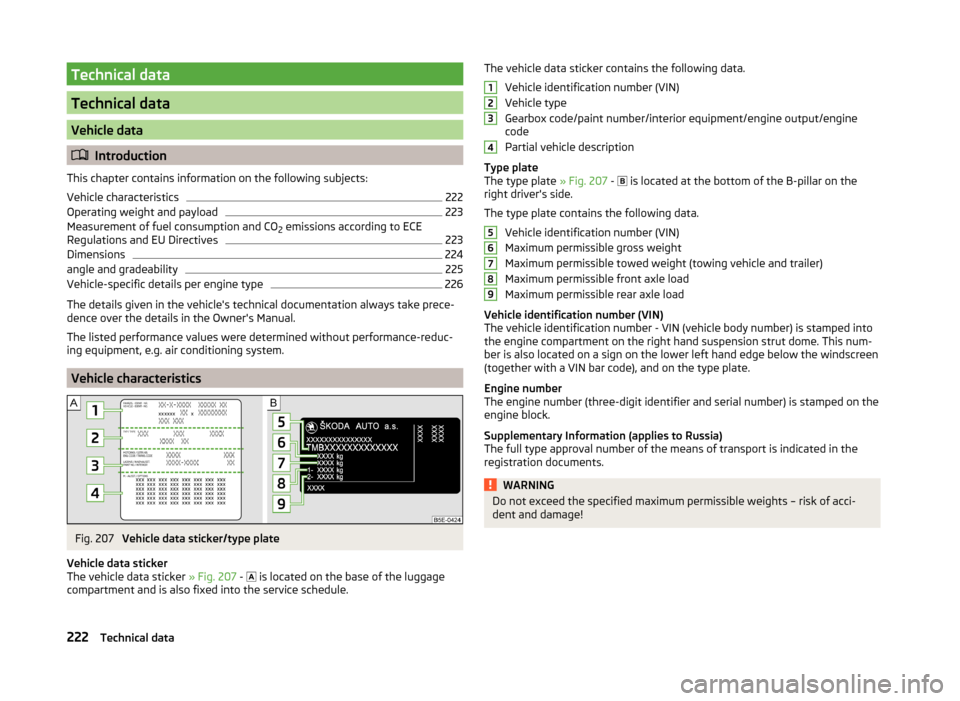
Fig. 207
Vehicle data sticker/type plate
Vehicle data sticker
The vehicle data sticker » Fig. 207 -
is located on the base of the luggage
compartment and is also fixed into the service schedule.
The vehicle data sticker contains the following data.
Vehicle identification number (VIN)
Vehicle type
Gearbox code/paint number/interior equipment/engine output/engine
code
Partial vehicle description
Type plate
The type plate » Fig. 207 -
is located at the bottom of the B-pillar on the
right driver's side.
The type plate contains the following data. Vehicle identification number (VIN)
Maximum permissible gross weight
Maximum permissible towed weight (towing vehicle and trailer)
Maximum permissible front axle load
Maximum permissible rear axle load
Vehicle identification number (VIN)
The vehicle identification number - VIN (vehicle body number) is stamped into
the engine compartment on the right hand suspension strut dome. This num-
ber is also located on a sign on the lower left hand edge below the windscreen
(together with a VIN bar code), and on the type plate.
Engine number
The engine number (three-digit identifier and serial number) is stamped on the engine block.
Supplementary Information (applies to Russia)
The full type approval number of the means of transport is indicated in the
registration documents.WARNINGDo not exceed the specified maximum permissible weights – risk of acci-
dent and damage!123456789222Technical data