gas type SKODA YETI 2014 1.G / 5L Owner's Manual
[x] Cancel search | Manufacturer: SKODA, Model Year: 2014, Model line: YETI, Model: SKODA YETI 2014 1.G / 5LPages: 248, PDF Size: 29.49 MB
Page 10 of 248

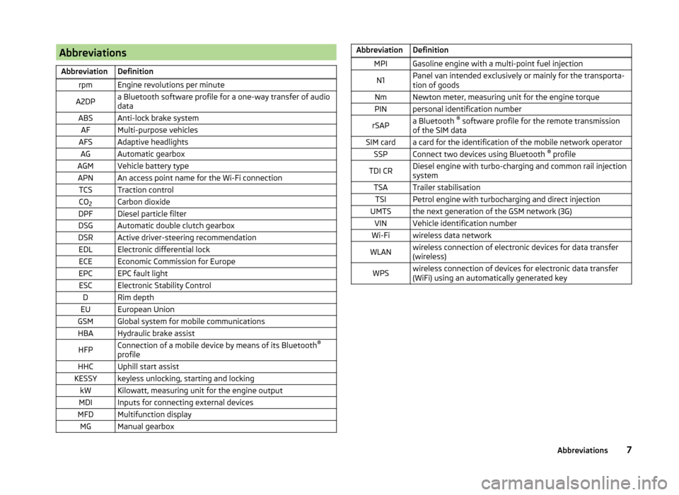
AbbreviationsAbbreviationDefinitionrpmEngine revolutions per minuteA2DPa Bluetooth software profile for a one-way transfer of audio
dataABSAnti-lock brake systemAFMulti-purpose vehiclesAFSAdaptive headlightsAGAutomatic gearboxAGMVehicle battery typeAPNAn access point name for the Wi-Fi connectionTCSTraction controlCO 2Carbon dioxideDPFDiesel particle filterDSGAutomatic double clutch gearboxDSRActive driver-steering recommendationEDLElectronic differential lockECEEconomic Commission for EuropeEPCEPC fault lightESCElectronic Stability ControlDRim depthEUEuropean UnionGSMGlobal system for mobile communicationsHBAHydraulic brake assistHFPConnection of a mobile device by means of its Bluetooth ®
profileHHCUphill start assistKESSYkeyless unlocking, starting and lockingkWKilowatt, measuring unit for the engine outputMDIInputs for connecting external devicesMFDMultifunction displayMGManual gearboxAbbreviationDefinitionMPIGasoline engine with a multi-point fuel injectionN1Panel van intended exclusively or mainly for the transporta-
tion of goodsNmNewton meter, measuring unit for the engine torquePINpersonal identification numberrSAPa Bluetooth ®
software profile for the remote transmission
of the SIM dataSIM carda card for the identification of the mobile network operatorSSPConnect two devices using Bluetooth ®
profileTDI CRDiesel engine with turbo-charging and common rail injection
systemTSATrailer stabilisationTSIPetrol engine with turbocharging and direct injectionUMTSthe next generation of the GSM network (3G)VINVehicle identification numberWi-Fiwireless data networkWLANwireless connection of electronic devices for data transfer
(wireless)WPSwireless connection of devices for electronic data transfer
(WiFi) using an automatically generated key7Abbreviations
Page 20 of 248

System descriptionRead and observe
on page 16 first.
The functional status of the airbag system is indicated by the
indicator light
in the instrument cluster » page 40.
When the airbags are deployed, they fill with gas and inflate.
A grey white or red, non-harmful gas is released when the airbag is inflated.
This is perfectly normal and is not an indication of a fire in the vehicle.
Depending on the vehicle equipment, the airbag system consists of the
following modules.
› Electronic control unit.
› Front airbag for the driver and the front passenger
» page 18.
› Driver’s knee airbag
» page 19.
› Side airbags
» page 19.
› Head airbags
» page 20.
› Airbag warning light in the instrument cluster
» page 40.
› Key switch for the front passenger airbag
» page 22.
› Warning light for the front passenger airbag deactivation/activation in the
middle of the dash panel » page 22.
Note
■
The airbag system needs no maintenance during its working life.■If you sell your vehicle, provide the complete vehicle documentation to the
new owner. Please note that the information relating to the possibility of de-
activating the front passenger airbag must be included!■
When disposing of vehicle or parts of the airbag system, it is important to
comply with the national legal requirements.
Airbag deployment
Read and observe
on page 16 first.
The airbags inflate in fractions of a second and at a high speed in order to beable to offer additional protection in the event of an accident.
The airbag system is only functional when the ignition is switched on.
In certain accident situations, the several airbags may be deployed simultane-
ously.
The airbags are not deployed in the case of minor frontal and side collisions,
rear-end collisions, tilting of the vehicle and vehicle rollover.
Deployment factors
It is not possible to generally determine which deployment conditions apply to
the airbag system in every situation. An important role is played by factors
such as the type of object that the vehicle hits (hard/soft), the impact angle,
vehicle speed etc.
A decisive factor for the deployment of the airbags is the deceleration which
occurs. The control unit analyses the nature of the collision and activates the
relevant restraint system.
If the vehicle deceleration which occurs and is measured during the collision
remains below the prescribed reference values specified in the control unit,
the airbags are not deployed although the vehicle may well suffer severe dam-
age to the bodywork as a consequence of the accident.
The following airbags will be deployed in the event of a severe frontal
collision.
› Driver’s front airbag.
› Front passenger airbag.
› Driver’s knee airbag.
The following airbags will be deployed in the event of a severe side collision.
› Front side airbag on the side of the accident.
› Rear side airbag on the side of the accident.
› Head airbags on the side of the accident.
When an airbag is deployed, the following events occur.
› The interior lighting comes on (if the switch for the interior light is in the door
contact position).
› The hazard warning lights are switched on.
› All doors are unlocked.
› The fuel supply to the engine is interrupted.
Airbag overview
Introduction
This chapter contains information on the following subjects:
Front airbags
18
Driver’s knee airbag
19
17Airbag system
Page 23 of 248

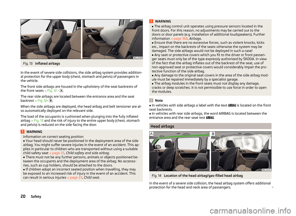
Fig. 13
Inflated airbags
In the event of severe side collisions, the side airbag system provides addition-
al protection for the upper body (chest, stomach and pelvis) of passengers in
the vehicle.
The front side airbags are housed in the upholstery of the seat backrests of
the front seats » Fig. 12 -
.
The rear side airbags are located between the entrance area and the seat
backrest » Fig. 12-
.
When the side airbags are deployed, the head airbag and belt tensioner are al-
so automatically deployed on the relevant side.
The load of the occupants is cushioned when plunging into the fully inflated
airbag » Fig. 13 and the risk of injury to the entire upper body (chest, stomach
and pelvis) is reduced on the side facing the door.
WARNINGInformation on correct seating position■Your head should never be positioned in the deployment area of the side
airbag. You might suffer severe injuries in the event of an accident. This ap-
plies in particular to children who are transported without using a suitable
child safety seat » page 25, Child safety and side airbag .■
There must not be any further persons, animals or objects positioned be-
tween the occupants and the deployment area of the airbag. No accesso-
ries, such as cup holders, should be attached to the doors.
■
If children adopt an incorrect seated position when travelling, they may
be exposed to an increased risk of injury in the event of an accident. This
can result in serious injuries » page 23, Child seat .
WARNING■
The airbag control unit operates using pressure sensors located in the
front doors. For this reason, no adjustments may be carried out to the
doors or door panels (e.g. installation of additional loudspeakers). Further
information » page 168, Airbags .■
Ensure that there are no excessive forces, such as violent knocks, kicks
etc., impact on the backrests of the seats otherwise the system may be
damaged. The side airbags would not be deployed in such a case!
■
Any seat or protective covers which you fit to the driver or front passen-
ger seats must only be of the type expressly authorized by ŠKODA. In view
of the fact that the airbag inflates out of the backrest of the seat, use of
non-approved seat or protective covers would considerably impair the pro-
tective function of the side airbag.
■
Any damage to the original seat covers in the area of the side airbag mod-
ule must be repaired immediately by a specialist garage.
■
The airbag modules in the front seats must not display any damage,
cracks or deep scratches. It is not permissible to use force in order to open
the modules.
Note
■ In vehicles with side airbags a label with the text is located on the front
seat backrests.■
In vehicles with rear side airbags, the word AIRBAG is located between the
entrance area and the rear seat rest
.
Head airbags
Fig. 14
Location of the head airbag/gas-filled head airbag
In the event of a severe side collision, the head airbag system offers additional
protection for the head and neck area of passengers.
20Safety
Page 220 of 248

No.Consumer21Lambda probe22Clutch pedal switch, brake pedal switch
23
Coolant pump
Solenoid valve for charge pressure control, change-over valve for
cooler
High-pressure fuel pump24Active charcoal filter, exhaust gas recirculation valve, radiator fan25ABS control unit26Vehicle voltage control unit, left headlight, left tail light27Glow plug system28Windscreen heater29Power to the internal fuse carrier30Terminal X a)a)
In order not to drain the battery unnecessarily when starting the engine, the electrical components of
this terminal are automatically switched off.
Replacing bulbs
Introduction
This chapter contains information on the following subjects:
Bulb arrangement in the headlights
218
Change bulb for low beam and high beam
218
Remove the protective grille for fog lights
218
Remove the protective grille for fog lights - sensor plug for parking
assistance
219
Replacing the bulb for the fog lights
219
Replacing the bulb for the licence plate light
220
Rear Light
220
Replacing bulbs in rear light
221
Some manual skills are required to change a bulb. For this reason, we recom-
mend having bulbs replaced by a specialist garage or seeking other expert help
in the event of any uncertainties.
› Switch off the ignition and all of the lights before replacing a bulb.
› Faulty bulbs must only be replaced with the same type of bulbs. The designa-
tion is located on the light socket or the glass bulb.
› A stowage compartment for replacement bulbs is located in a box under the
floor covering in the luggage compartment.WARNING■ Always read and observe the warnings before completing any work in the
engine compartment » page 180.■
Accidents can be caused if the road in front of the vehicle is not suffi-
ciently illuminated and the vehicle cannot or can only be seen with difficul-
ty by other road users.
■
Bulbs H7 and H4 are pressurised and may burst when changed - there is a
risk of injury. We therefore recommended wearing gloves and safety
glasses when changing a bulb.
■
Gas discharge bulbs (xenon bulbs) operate with a high voltage, professio-
nal knowledge is required – risk of death!
■
Switch off the respective vehicle light when changing the bulb.
CAUTION
Do not take hold of the glass bulb with naked fingers (even the smallest
amount of dirt reduces the working life of the light bulb). Use a clean cloth,
napkin, or similar.
Note
■ This Owner's Manual only describes the replacement of bulbs where it is pos-
sible to replace the bulbs on your own without any complications arising. Other
bulbs must be replaced by a specialist garage.■
We recommend that a box of replacement bulbs always be carried in the ve-
hicle. Replacement bulbs can be purchased from ŠKODAOriginal Accessories.
■
We recommend having the headlight settings checked by a specialist garage
after replacing a bulb in the main beam, low beam or fog lights.
■
In case of failure of a xenon gas discharge lamp or an LED diode, visit a spe-
cialist garage.
217Fuses and light bulbs