Data SKODA YETI 2015 1.G / 5L User Guide
[x] Cancel search | Manufacturer: SKODA, Model Year: 2015, Model line: YETI, Model: SKODA YETI 2015 1.G / 5LPages: 232, PDF Size: 30.84 MB
Page 49 of 232
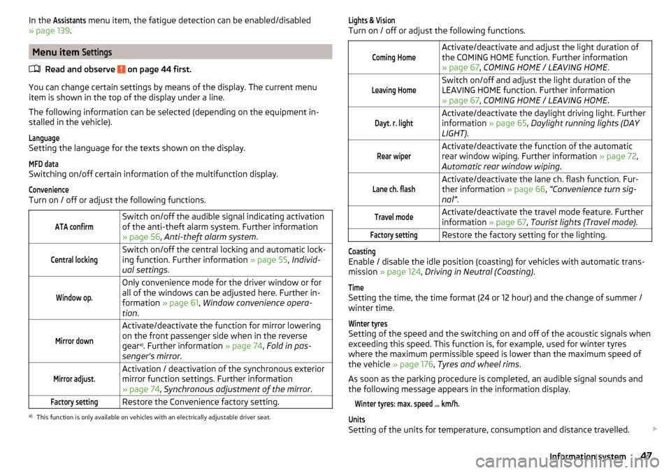
In the Assistants menu item, the fatigue detection can be enabled/disabled
» page 139 .
Menu item
Settings
Read and observe on page 44 first.
You can change certain settings by means of the display. The current menu
item is shown in the top of the display under a line.
The following information can be selected (depending on the equipment in- stalled in the vehicle).
Language
Setting the language for the texts shown on the display.
MFD data
Switching on/off certain information of the multifunction display.
Convenience
Turn on / off or adjust the following functions.
ATA confirmSwitch on/off the audible signal indicating activation
of the anti-theft alarm system. Further information
» page 56 , Anti-theft alarm system .Central lockingSwitch on/off the central locking and automatic lock-
ing function. Further information » page 55, Individ-
ual settings .Window op.Only convenience mode for the driver window or for
all of the windows can be adjusted here. Further in-
formation » page 61, Window convenience opera-
tion .Mirror downActivate/deactivate the function for mirror lowering
on the front passenger side when in the reverse
gear a)
. Further information » page 74, Fold in pas-
senger's mirror .Mirror adjust.Activation / deactivation of the synchronous exterior
mirror function settings. Further information
» page 74 , Synchronous adjustment of the mirror .Factory settingRestore the Convenience factory setting.a)
This function is only available on vehicles with an electrically adjustable driver seat.
Lights & Vision
Turn on / off or adjust the following functions.
Coming HomeActivate/deactivate and adjust the light duration of
the COMING HOME function. Further information
» page 67 , COMING HOME / LEAVING HOME .Leaving HomeSwitch on/off and adjust the light duration of the
LEAVING HOME function. Further information
» page 67 , COMING HOME / LEAVING HOME .Dayt. r. lightActivate/deactivate the daylight driving light. Further
information » page 65, Daylight running lights (DAY
LIGHT) .Rear wiperActivate/deactivate the function of the automatic
rear window wiping. Further information » page 72,
Automatic rear window wiping .Lane ch. flashActivate/deactivate the lane ch. flash function. Fur-
ther information » page 66, “Convenience turn sig-
nal” .Travel modeActivate/deactivate the travel mode feature. Further
information » page 67, Tourist lights (Travel mode) .Factory settingRestore the factory setting for the lighting.Coasting
Enable / disable the idle position (coasting) for vehicles with automatic trans-
mission » page 124 , Driving in Neutral (Coasting) .
Time
Setting the time, the time format (24 or 12 hour) and the change of summer /
winter time.
Winter tyres
Setting of the speed and the switching on and off of the acoustic signals when
exceeding this speed. This function is, for example, used for winter tyres
where the maximum permissible speed is lower than the maximum speed of
the vehicle » page 176, Tyres and wheel rims .
As soon as the parking procedure is completed, an audible signal sounds and
the following message appears in the information display.
Winter tyres: max. speed ... km/h.Units
Setting of the units for temperature, consumption and distance travelled.
47Information system
Page 51 of 232
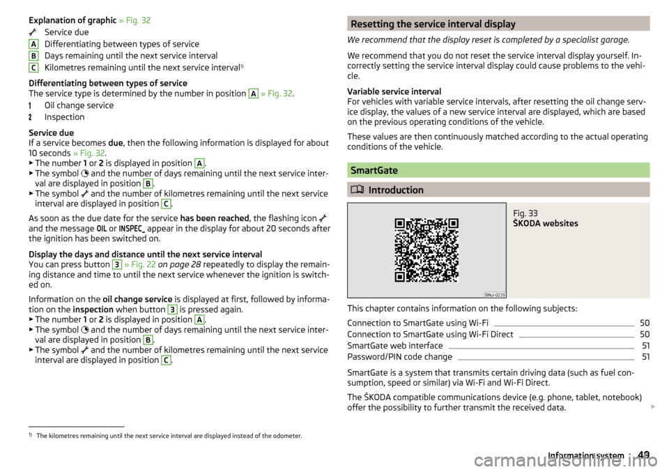
Explanation of graphic » Fig. 32
Service due
Differentiating between types of service
Days remaining until the next service interval
Kilometres remaining until the next service interval 1)
Differentiating between types of service
The service type is determined by the number in position A
» Fig. 32 .
Oil change service
Inspection
Service due
If a service becomes due, then the following information is displayed for about
10 seconds » Fig. 32.
▶ The number 1 or 2 is displayed in position
A
.
▶ The symbol and the number of days remaining until the next service inter-
val are displayed in position
B
.
▶ The symbol and the number of kilometres remaining until the next service
interval are displayed in position
C
.
As soon as the due date for the service has been reached, the flashing icon
and the message
OIL
or
INSPEC_
appear in the display for about 20 seconds after
the ignition has been switched on.
Display the days and distance until the next service interval
You can press button
3
» Fig. 22 on page 28 repeatedly to display the remain-
ing distance and time to until the next service whenever the ignition is switch-
ed on.
Information on the oil change service is displayed at first, followed by informa-
tion on the inspection when button
3
is pressed again.
▶ The number 1 or 2 is displayed in position
A
.
▶ The symbol and the number of days remaining until the next service inter-
val are displayed in position
B
.
▶ The symbol and the number of kilometres remaining until the next service
interval are displayed in position
C
.
ABCResetting the service interval display
We recommend that the display reset is completed by a specialist garage.
We recommend that you do not reset the service interval display yourself. In-
correctly setting the service interval display could cause problems to the vehi-
cle.
Variable service interval
For vehicles with variable service intervals, after resetting the oil change serv-
ice display, the values of a new service interval are displayed, which are based
on the previous operating conditions of the vehicle.
These values are then continuously matched according to the actual operating
conditions of the vehicle.
SmartGate
Introduction
Fig. 33
ŠKODA websites
This chapter contains information on the following subjects:
Connection to SmartGate using Wi-Fi
50
Connection to SmartGate using Wi-Fi Direct
50
SmartGate web interface
51
Password/PIN code change
51
SmartGate is a system that transmits certain driving data (such as fuel con-
sumption, speed or similar) via Wi-Fi and Wi-Fi Direct.
The ŠKODA compatible communications device (e.g. phone, tablet, notebook)
offer the possibility to further transmit the received data.
1)
The kilometres remaining until the next service interval are displayed instead of the odometer.
49Information system
Page 52 of 232
More information on available applications, a list of compatible communication
devices and on SmartGate, can be found on the ŠKODA website » Fig. 33.
http://www.skoda-auto.comWARNING■ The general binding country-specific regulations for operating communi-
cation devices in the vehicle must be observed.■
Never leave a communication device in the deployment area of an airbag,
on a seat, on the dash panel or any another area, from which it can be
thrown during a sudden braking manoeuvre, an accident or a collision - risk
of injury!
■
Never connect or disconnect a communication device while driving - risk
of accident!
CAUTION
■ To increase the access security to the transmitted vehicle data, once the
ŠKODA application has been started, you are requested to change the pass-
word/PIN code if the default password/PIN code has not yet been changed
» page 51 , Password/PIN code change . It is not possible to start the ŠKODA
application without changing it.■
ŠKODA accepts no responsibility for any problems caused by incompatibility
or improper functioning of the communication devices.
Note
The ŠKODA applications, support communications devices with the Android
operating system version 4.x.x and later and iOS 7.x.x and higher.
Connection to SmartGate using Wi-Fi
Read and observe
and on page 50 first.
Connecting to an Android communication device
›
Switch on the ignition.
›
Switch on the Wi-Fi on the communication device to be connected.
›
Start the SmartGate application using the communication device to be con-
nected.
›
Then follow the instructions in the manual, which are included in the
SmartGate application.
With SmartGate, a maximum of four communication devices can be connected
simultaneously using Wi-Fi, with as many launched ŠKODA applications as re-
quired.
Connecting to an iOS communication device›
Switch on the ignition.
›
Switch on the Wi-Fi on the communication device to be connected.
›
Allow the communication device to be connected to search for available Wi-
Fi networks (see the Owner's Manual for the communication device to be
connected).
›
In the menu of the detected networks select “SmartGate_...” 1)
or “DIRECT
SmartGate_...” 1)
.
›
Enter the password » page 51.
With SmartGate, a maximum of four communication devices can be connected
simultaneously using Wi-Fi. In these communication devices, up to four ŠKODA
applications can be started simultaneously.
Disconnection
The connection can be switched off in one of the following ways.
›
Switch off the ignition for longer than 5 seconds (for vehicles with a starter
button, switch off the engine and open the driver's door).
›
End the connection in the SmartGate application.
›
Switch off the Wi-Fi on the connected communication device.
Automatic connection
If the communication device once had a connection with SmartGate, then the
connection is automatically restored under the following conditions.
The ignition is switched on.
The Wi-Fi on the communication device to be connected is switched on.
The communication device to be connected stores the password required
for the connection check.
Connection to SmartGate using Wi-Fi Direct
Read and observe
and on page 50 first.
This type of connection is intended for communication devices running theAndroid operating system.
1)
The last 6 characters of the VIN vehicle identification number of your vehicle are displayed at position
....
50Using the system
Page 68 of 232
The headlight flasher can be operated even if the ignition is switched off.
The turn signal light switches itself off automatically when driving around a
curve or after making a turn.
“Convenience turn signal”
When the control lever is lightly pressed to the pressure point A
or
B
then
the respective turn-signal lamp flashes three times.
The “Lane ch. flash” can be activated / deactivated via the Maxi DOT display in
the
Lane ch. flash
» page 47 , Menu item
Settings
menu item.
WARNINGOnly turn on the main beam or the headlight flasher if other road users will
not be dazzled.
Automatic driving lamp control
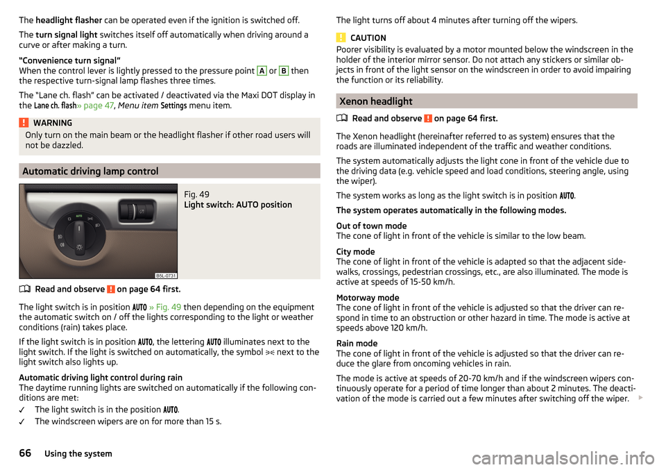
Fig. 49
Light switch: AUTO position
Read and observe on page 64 first.
The light switch is in position
» Fig. 49 then depending on the equipment
the automatic switch on / off the lights corresponding to the light or weather
conditions (rain) takes place.
If the light switch is in position
, the lettering
illuminates next to the
light switch. If the light is switched on automatically, the symbol
next to the
light switch also lights up.
Automatic driving light control during rain
The daytime running lights are switched on automatically if the following con-
ditions are met:
The light switch is in the position
.
The windscreen wipers are on for more than 15 s.
The light turns off about 4 minutes after turning off the wipers.
CAUTION
Poorer visibility is evaluated by a motor mounted below the windscreen in the
holder of the interior mirror sensor. Do not attach any stickers or similar ob-
jects in front of the light sensor on the windscreen in order to avoid impairing
the function or its reliability.
Xenon headlight
Read and observe
on page 64 first.
The Xenon headlight (hereinafter referred to as system) ensures that the
roads are illuminated independent of the traffic and weather conditions.
The system automatically adjusts the light cone in front of the vehicle due to
the driving data (e.g. vehicle speed and load conditions, steering angle, using
the wiper).
The system works as long as the light switch is in position .
The system operates automatically in the following modes.
Out of town mode
The cone of light in front of the vehicle is similar to the low beam.
City mode
The cone of light in front of the vehicle is adapted so that the adjacent side-
walks, crossings, pedestrian crossings, etc., are also illuminated. The mode is
active at speeds of 15-50 km/h.
Motorway mode
The cone of light in front of the vehicle is adjusted so that the driver can re-
spond in time to an obstruction or other hazard in time. The mode is active at
speeds above 120 km/h.
Rain mode
The cone of light in front of the vehicle is adjusted so that the driver can re-
duce the glare from oncoming vehicles in rain.
The mode is active at speeds of 20-70 km/h and if the windscreen wipers con-
tinuously operate for a period of time longer than about 2 minutes. The deacti-
vation of the mode is carried out a few minutes after switching off the wiper.
66Using the system
Page 127 of 232
New tyres
New tyres must firstly be “run in”, as they do not offer optimal grip at first.
Therefore, drive especially carefully for the first 500 km or so.
New brake pads
New brake pads have to first “grind in” because these do not initially have the
best possible braking effect.
Therefore, drive especially carefully for the first 200 km or so.
Tips for economical driving
To achieve the lowest possible fuel consumption, the following instructions
must be observed.
Looking ahead when driving
Avoid unnecessary acceleration and braking.
Switch in an energy saving and timely manner Observe the recommended gear » page 40.
Avoid full throttle and high speeds
Fuel consumption can be reduced by half if only three-quarters of the possible
top speed of your vehicle is used.
Reducing idling
If the vehicle is fitted with the START - STOP system there is an automatic re-
duction of the idling. If the engine is stopped on vehicles without START-STOP
system, such as when waiting in a traffic jam, the fuel economy is already
greater after 30 - 40 s than the fuel quantity which is required for engine re-
start.
Avoid short distances
When driving a short distance of less than about 4 km, the engine cannot
reach its operating temperature. As long as the engine has not reached oper-
ating temperature, the fuel consumption is significantly higher than with the
engine hot.
Pay attention to the correct tyre inflation pressure being maintained
Further information » page 176.
Avoid unnecessary ballast
Per 100 kg of weight, consumption increases by about 0.3 l/100 km. At a speed
of 100 - 120 km/h, a vehicle fitted with a roof rack cross member without a load
will use about 10 % more fuel than normal due to the increased aerodynamic
drag.
Saving electricity
Only turn on electrical consumers (e.g. seat, window and mirror heating, etc.)
for as long as necessary.
Use the cooling system economically
The air conditioning system compressor uses power from the engine when in
cooling mode, which will affect the fuel consumption.
It recommended to open the windows or the doors of a vehicle for which the
interior has been strongly heated through the effect of direct sunlight in order
to allow the heated air to escape.
The cooling system should not be on if the windows are open.
Avoiding damage to your vehicle
Introduction
This chapter contains information on the following subjects:
Driving Tips
125
Driving through water
126
This section of the manual contains important information on preventing dam-
age to the vehicle while driving.
Driving Tips
Only drive on such roads and in such terrain, which match the vehicle parame-
ters » page 204 , Technical data as well as your driving skills.
The driver is always responsible for deciding whether the vehicle can handle
travelling in the given terrain.
When travelling off paved roads, we recommend activating the OFF ROAD
mode » page 129 .
125Starting-off and Driving
Page 137 of 232
Note■The orientation lines are immobile, and therefore the spacing of the bars be-
hind the vehicle will vary, depending on the vehicle load state and the road in-
clination.■
If reduced park assistance display is switched off the acoustic signal cannot
be turned off with the button
.
Park Assist
Introduction
This chapter contains information on the following subjects:
Functioning
135
Parking space search
136
Parking
137
Departing from a parallel parking space
137
Automatic brake assist
138
Information messages
138
Park Assist (hereinafter referred to as system) helps drivers park in suitable
parallel and perpendicular parking places or also to manoeuvre out of parallel
parking spaces.
The system takes over the steering movements when parking or leaving a
parking space. The driver operates the pedals and the shift lever or gear selec-
tor.
The state in which the steering wheel is operated by the system, is referred to
as parking operation.
The Park Assist is an extension of the parking aid » page 131 and operates on
the basis of data collected by the ultrasonic sensors.
For this reason, the chapter on the parking aid is to be read carefully and the safety notes are to be observed.
WARNING■ The general information relating to the use of assistance systems must
be observed » page 127, in section Introduction .■
During the parking process, the system automatically performs rapid
steering movements. While it is doing so, do not place your hands between
the steering wheel – risk of injury!
■
During a parking manoeuvre on loose or slippery surfaces (gravel, snow,
ice, etc.) you may stray from the calculated road. Therefore we suggest that
you do not use the system in such situations.
CAUTION
The correct evaluation of the parking space and the parking procedure de-
pends on the circumference of the wheels on the vehicle.■
The system only works correctly if the vehicle is fitted with the wheel size
approved by the manufacturer.
■
Abstain from using the system when the vehicle is fitted with snow chains or
a temporary spare wheel.
■
If wheels other than those approved by the manufacturer are mounted, the
resulting position of the vehicle in the parking space can differ slightly. This
can be avoided by readjusting the system at a specialist garage.
CAUTION
If other vehicles are parked behind the kerb or on it, the system can also guide
your vehicle beyond the kerb or onto it. Ensure that the wheels or the wheel
rims of your vehicle are not damaged and if necessary intervene in time.
Note
■ We recommend performing the parking at a safe speed to about 5 km / h.■The driver can stop the parking process at any time by pressing the symbol
key
» Fig. 149 on page 136 or by a driver steering intervention.
Functioning
Read and observe
and on page 135 first.
The system support is provided in the following manner.▶ While the parking space search is going on, a measurement and evaluation of
the parking space size is completed.
▶ Suitable parking spaces are shown in the display of the instrument cluster
(hereinafter only in the display).
135Assist systems
Page 177 of 232
CAUTIONOn vehicles with the START / STOP system or additional heating (auxiliary
heating), do not connect the pole terminal of the charger directly to the nega-
tive terminal of the vehicle battery but only to the engine earth » page 189.
Replacing
Read and observe
and on page 172 first.
The new vehicle battery must have the same capacity, voltage, current and the
same size as the original Battery. Suitable vehicle battery types can be pur-
chased from a specialist garage.
We recommend you have the battery replaced by a specialist garage.
Disconnecting and reconnecting
Read and observe
and on page 172 first.
Disconnecting
›
Switch off the ignition.
›
Disconnect the negative terminal first and then the positive
terminal of
the battery.
Connecting
›
Connect the positive terminal first, then the negative
battery terminal.
After disconnecting and re-connecting the vehicle battery, the following func-
tions or devices are partially or completely inoperative.
Function / deviceOperating measureElectrical power windows» page 61Panorama sliding/tilting roof» page 62Sun screen» page 63RadioEnter code » Owner's Manual
RadioTime settings» page 30CAUTION■ Disconnect the vehicle battery only with the ignition turned off - there is a
risk of damaging the electrical system of the vehicle.■
Under no circumstances must the battery cables be connected incorrectly –
risk of a cable fire.
Note
■ After disconnecting and re-connecting the vehicle battery, we recommend
having the vehicle checked by a specialist to ensure that the full functionality
of all electrical systems is guaranteed.■
The data of the multi-function display will be reset.
Automatic load deactivation
Read and observe
and on page 172 first.
The vehicle's electrical system automatically prevents the battery from dis-
charging when the battery is being heavily used. This manifests itself by the
following. ▶ The idling speed is raised to allow the generator to deliver more electricity to
the electrical system.
▶ Where necessary, large convenience consumers such as seat heaters and
rear window heaters have their power limited or are shut off completely in
the event of an emergency.
CAUTION
■ Despite such intervention by the vehicle electric system management, the
vehicle battery may be drained. For example, when the ignition is switched on
a long time with the engine turned off or the side or parking lights are turned
on during longer parking.■
Consumers that are supplied via a 12-V power socket can cause the vehicle
battery to discharge when the ignition is switched off.
Note
Driving comfort is not impaired by consumers being deactivated. The driver is
often not aware of it having taken place.175Inspecting and replenishing
Page 179 of 232
Tyre diameter in inches
These details are intended only as information for the specified tyre pres-
sure and does not list approved tyre sizes for your vehicle.
The approved tyre sizes for your vehicle are listed in the vehicle's technical
documentation (the so called COC document) and this also states the dec-
laration of conformity.
The approved tyre diameter for your vehicle is also provided with the vehi-
cle data » page 204 .
Tyre pressure value on the front axle
Tyre pressure value on the rear axle
Check tyre pressures
Check the tyre pressure, including that of the emergency or spare wheel, at
least once a month and also before setting off on a long journey.
Always check the inflation pressure when the tyres are cold. Do not reduce the
higher pressure of warm tyres.
In vehicles with tyre pressure monitoring, tyre pressure values must be stored
every time the tyre pressure changes » page 141.WARNING■
Having the correct tyre inflation pressure is always the driver's responsi-
bility.■
Too low or too high inflation pressure impairs handling.
■
If the inflation pressure is too low, the tyre will have to overcome a higher
rolling resistance. This will cause a significant increase in the temperature
of the tyre, especially at higher speeds. This can result in tread separation
and a tyre blow-out.
■
In the event of very fast tyre inflation pressure loss, such as a sudden tyre
failure, an attempt should be made to bring the vehicle carefully to a stop
without sudden steering movements and without any hard braking.
For the sake of the environment
Tyres that are insufficiently inflated increase your fuel consumption.
Note
The declaration of conformity (COC document), can be obtained from a ŠKODA 1)
partner.EFGTyre wear
Read and observe
on page 176 first.
Tyre wear depends on the pressure, driving style, and other circumstances.
Attention to the following factors can reduce tyre wear.
Driving style
Fast cornering, sharp acceleration and braking increase the wear of your tyres.
Wheel balance
The wheels of a new vehicle are balanced. When driving, however, there are a
range of factors that may result in an imbalance. This may become apparent by
a “vibration” in the steering. If this is the case, have the wheels checked by a
specialist garage.
Have the wheels likewise rebalanced after replacing the tyres.
Setting the vehicle geometry
Incorrect wheel alignment at the front or rear leads to excess wear on the
tyres and impairs driving safety. With a distinct tyre wear pattern, we recom-
mend that you check the setting of the vehicle geometry in a specialist work-
shop.
WARNING■ An incorrect wheel alignment at the front or rear impairs handling.■Unusual vibrations or pulling of the vehicle to one side could be a sign of
tyre damage. If there is any doubt that a wheel is damaged, immediately re-
duce your speed and stop! If no external tyre damage is evident, drive slow-
ly and carefully to the nearest specialist garage to have the vehicle
checked.1)
Only valid for some countries and some models.
177Wheels
Page 200 of 232
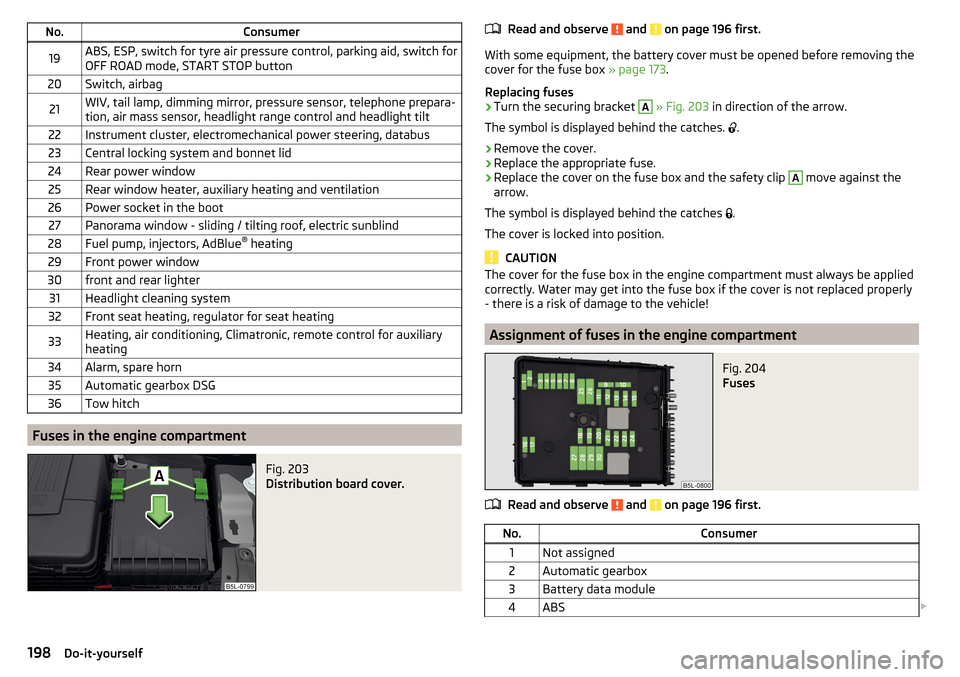
No.Consumer19ABS, ESP, switch for tyre air pressure control, parking aid, switch for
OFF ROAD mode, START STOP button20Switch, airbag21WIV, tail lamp, dimming mirror, pressure sensor, telephone prepara-
tion, air mass sensor, headlight range control and headlight tilt22Instrument cluster, electromechanical power steering, databus23Central locking system and bonnet lid24Rear power window25Rear window heater, auxiliary heating and ventilation26Power socket in the boot27Panorama window - sliding / tilting roof, electric sunblind28Fuel pump, injectors, AdBlue ®
heating29Front power window30front and rear lighter31Headlight cleaning system32Front seat heating, regulator for seat heating33Heating, air conditioning, Climatronic, remote control for auxiliary
heating34Alarm, spare horn35Automatic gearbox DSG36Tow hitch
Fuses in the engine compartment
Fig. 203
Distribution board cover.
Read and observe and on page 196 first.
With some equipment, the battery cover must be opened before removing the
cover for the fuse box » page 173.
Replacing fuses
›
Turn the securing bracket
A
» Fig. 203 in direction of the arrow.
The symbol is displayed behind the catches.
.
›
Remove the cover.
›
Replace the appropriate fuse.
›
Replace the cover on the fuse box and the safety clip
A
move against the
arrow.
The symbol is displayed behind the catches .
The cover is locked into position.
CAUTION
The cover for the fuse box in the engine compartment must always be applied
correctly. Water may get into the fuse box if the cover is not replaced properly
- there is a risk of damage to the vehicle!
Assignment of fuses in the engine compartment
Fig. 204
Fuses
Read and observe and on page 196 first.
No.Consumer1Not assigned2Automatic gearbox3Battery data module4ABS 198Do-it-yourself
Page 201 of 232
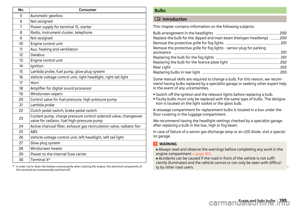
No.Consumer5Automatic gearbox6Not assigned7Power supply for terminal 15, starter8Radio, instrument cluster, telephone9Not assigned10Engine control unit11Aux. heating and ventilation12Databus13Engine control unit14Ignition15Lambda probe, fuel pump, glow plug system16Vehicle voltage control unit, right headlight, right tail light17Horn18Amplifier for digital sound processor19Windscreen wipers20Control valve for fuel pressure, high pressure pump21Lambda probe22Clutch pedal switch, brake pedal switch23Coolant pump, charge pressure control solenoid valve, changeover
valve for radiator, fuel high-pressure pump24Active charcoal filter, exhaust gas recirculation valve, radiator fan25ABS26Vehicle voltage control unit, left headlight, left tail light27Glow plug system28Windscreen heater29Power to the internal fuse carrier30Terminal X a)a)
In order not to drain the battery unnecessarily when starting the engine, the electrical components of
this terminal are automatically switched off.
Bulbs
Introduction
This chapter contains information on the following subjects:
Bulb arrangement in the headlights
200
Replace the bulb for the dipped and main beam (Halogen headlamp)
200
Remove the protective grille for fog lights
201
Remove the protective grille for fog lights - sensor plug for parking
assistance
201
Replacing the bulb for the fog lights
201
Replacing the bulb for the licence plate light
202
Rear Light
202
Replacing bulbs in rear light
203
Some manual skills are required to change a bulb. For this reason, we recom-
mend having bulbs replaced by a specialist garage or seeking other expert help
in the event of any uncertainties.
▶ Switch off the ignition and the relevant lights before replacing a bulb.
▶ Faulty bulbs must only be replaced with the same type of bulbs. The designa-
tion is located on the light socket or the glass bulb.
A stowage compartment for replacement bulbs is located in a box under the floor covering in the luggage compartment.
We recommend having the headlight settings checked by a specialist garage after replacing a bulb in the low, high or fog beam.
In case of failure of a xenon gas discharge lamp or an LED diode, visit a special- ist garage.
WARNING■ Always read and observe the warnings before completing any work in the
engine compartment » page 165.■
Accidents can be caused if the road in front of the vehicle is not suffi-
ciently illuminated and the vehicle cannot or can only be seen with difficul-
ty by other road users.
199Fuses and light bulbs