ESP SKODA YETI 2015 1.G / 5L User Guide
[x] Cancel search | Manufacturer: SKODA, Model Year: 2015, Model line: YETI, Model: SKODA YETI 2015 1.G / 5LPages: 232, PDF Size: 30.84 MB
Page 52 of 232
More information on available applications, a list of compatible communication
devices and on SmartGate, can be found on the ŠKODA website » Fig. 33.
http://www.skoda-auto.comWARNING■ The general binding country-specific regulations for operating communi-
cation devices in the vehicle must be observed.■
Never leave a communication device in the deployment area of an airbag,
on a seat, on the dash panel or any another area, from which it can be
thrown during a sudden braking manoeuvre, an accident or a collision - risk
of injury!
■
Never connect or disconnect a communication device while driving - risk
of accident!
CAUTION
■ To increase the access security to the transmitted vehicle data, once the
ŠKODA application has been started, you are requested to change the pass-
word/PIN code if the default password/PIN code has not yet been changed
» page 51 , Password/PIN code change . It is not possible to start the ŠKODA
application without changing it.■
ŠKODA accepts no responsibility for any problems caused by incompatibility
or improper functioning of the communication devices.
Note
The ŠKODA applications, support communications devices with the Android
operating system version 4.x.x and later and iOS 7.x.x and higher.
Connection to SmartGate using Wi-Fi
Read and observe
and on page 50 first.
Connecting to an Android communication device
›
Switch on the ignition.
›
Switch on the Wi-Fi on the communication device to be connected.
›
Start the SmartGate application using the communication device to be con-
nected.
›
Then follow the instructions in the manual, which are included in the
SmartGate application.
With SmartGate, a maximum of four communication devices can be connected
simultaneously using Wi-Fi, with as many launched ŠKODA applications as re-
quired.
Connecting to an iOS communication device›
Switch on the ignition.
›
Switch on the Wi-Fi on the communication device to be connected.
›
Allow the communication device to be connected to search for available Wi-
Fi networks (see the Owner's Manual for the communication device to be
connected).
›
In the menu of the detected networks select “SmartGate_...” 1)
or “DIRECT
SmartGate_...” 1)
.
›
Enter the password » page 51.
With SmartGate, a maximum of four communication devices can be connected
simultaneously using Wi-Fi. In these communication devices, up to four ŠKODA
applications can be started simultaneously.
Disconnection
The connection can be switched off in one of the following ways.
›
Switch off the ignition for longer than 5 seconds (for vehicles with a starter
button, switch off the engine and open the driver's door).
›
End the connection in the SmartGate application.
›
Switch off the Wi-Fi on the connected communication device.
Automatic connection
If the communication device once had a connection with SmartGate, then the
connection is automatically restored under the following conditions.
The ignition is switched on.
The Wi-Fi on the communication device to be connected is switched on.
The communication device to be connected stores the password required
for the connection check.
Connection to SmartGate using Wi-Fi Direct
Read and observe
and on page 50 first.
This type of connection is intended for communication devices running theAndroid operating system.
1)
The last 6 characters of the VIN vehicle identification number of your vehicle are displayed at position
....
50Using the system
Page 56 of 232
The sensors for unlocking or locking are located in the handle of the front
door.
Unlocking
Locking
When unlocking or locking the vehicle, the key must be at a maximum distance
of approximately 1.5 m from the front door handle.
Locking
On vehicles fitted with automatic gearbox, the selector lever must be moved
into the position P before unlocking.
The vehicle cannot be locked from the outside if the ignition has not been
turned off.
After locking the vehicle, it is not possible to unlock it within the next 2 sec-
onds by touching the door handle. This can be used to check whether the vehi-
cle is locked.
Protection against inadvertently locking the key in the vehicle
If one of the doors is closed after locking the vehicle and the key with which
the vehicle was locked remains in the passenger compartment, the vehicle is
automatically unlocked. After unlocking the vehicle again, the turn-signal
lights flash four times. If no door is opened within 45 seconds, the vehicle is
automatically locked again.
If the boot lid is closed after locking the vehicle and the key with which the
vehicle was locked remains in the luggage compartment, the lid is unlocked
(partially opened). The turn-signal lights flash four times as an indication that
the boot lid has been unlocked again. The luggage compartment lid remains
released (partially open).
The following message is shown in the information cluster display.Key in vehicle.KEY IN VEHICLE
CAUTION
■ Some types of gloves can affect the unlocking or locking device in the door
handle.■
After leaving the car there is no automatic locking.
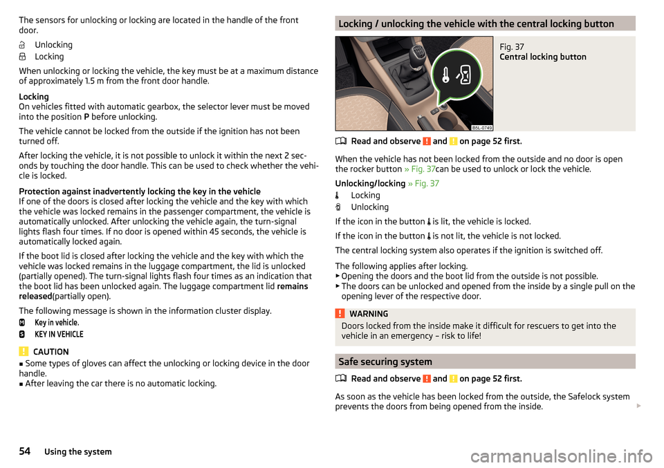
Locking / unlocking the vehicle with the central locking buttonFig. 37
Central locking button
Read and observe and on page 52 first.
When the vehicle has not been locked from the outside and no door is open
the rocker button » Fig. 37can be used to unlock or lock the vehicle.
Unlocking/locking » Fig. 37
Locking
Unlocking
If the icon in the button is lit, the vehicle is locked.
If the icon in the button is not lit, the vehicle is not locked.
The central locking system also operates if the ignition is switched off.
The following applies after locking. ▶ Opening the doors and the boot lid from the outside is not possible.
▶ The doors can be unlocked and opened from the inside by a single pull on the
opening lever of the respective door.
WARNINGDoors locked from the inside make it difficult for rescuers to get into the
vehicle in an emergency – risk to life!
Safe securing system
Read and observe
and on page 52 first.
As soon as the vehicle has been locked from the outside, the Safelock system
prevents the doors from being opened from the inside.
54Using the system
Page 61 of 232
NoteWhen driving always use the existing heating, air conditioning and ventilation
system for ventilating the interior of the vehicle. If the windows are opened,
dust as well as other dirt can get into the vehicle and in addition the wind
noise is more at certain speeds.
Mechanical window lefter
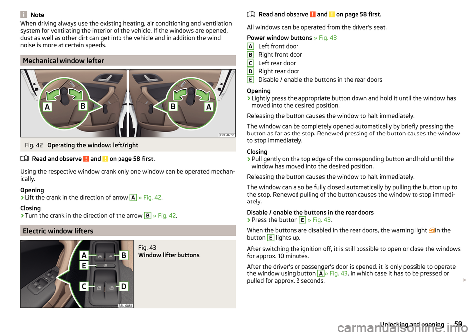
Fig. 42
Operating the window: left/right
Read and observe
and on page 58 first.
Using the respective window crank only one window can be operated mechan-
ically.
Opening
›
Lift the crank in the direction of arrow
A
» Fig. 42 .
Closing
›
Turn the crank in the direction of the arrow
B
» Fig. 42 .
Electric window lifters
Fig. 43
Window lifter buttons
Read and observe and on page 58 first.
All windows can be operated from the driver's seat.
Power window buttons » Fig. 43
Left front door
Right front door
Left rear door
Right rear door
Disable / enable the buttons in the rear doors
Opening
›
Lightly press the appropriate button down and hold it until the window has
moved into the desired position.
Releasing the button causes the window to halt immediately.
The window can be completely opened automatically by briefly pressing the
button as far as the stop. Renewed pressing of the button causes the window
to stop immediately.
Closing
›
Pull gently on the top edge of the corresponding button and hold until the
window has moved into the desired position.
Releasing the button causes the window to halt immediately.
The window can also be fully closed automatically by pulling the button up to
the stop. Renewed pulling of the button causes the window to stop immedi-
ately.
Disable / enable the buttons in the rear doors
›
Press the button
E
» Fig. 43 .
When the buttons are disabled in the rear doors, the warning light in the
button
E
lights up.
After switching the ignition off, it is still possible to open or close the windows
for approx. 10 minutes.
After the driver's or passenger's door is opened, it is only possible to operate
the window using button
A
» Fig. 43 , in which case it has to be pressed or
pulled for approx. 2 seconds.
ABCDE59Unlocking and opening
Page 63 of 232
Window convenience operationRead and observe
and on page 58 first.
The convenience operation of the windows offers the possibility of opening orclosing all the windows at once.
Convenience operation can take place in one of the following ways.
Opening
›
Press and hold the symbol button
on the key.
›
Keep the key in the locking cylinder of the driver's door in the unlock position
until all electrically operated windows are open.
›
Press and hold he central locking button in the area of the symbol
» Fig. 37
on page 54 .
›
Switch off the ignition, open the driver's door and hold the key
A
until it
stops in the open position » Fig. 43 on page 59 .
Closing
›
Press and hold the symbol button on the key.
›
Keep the key in the locking cylinder of the driver's door in the lock position
until all the electrically operated windows are closed.
›
Press and hold he central locking button in the area of the symbol
» Fig. 37
on page 54 .
›
Switch off the ignition, open the driver's door and hold the key
A
until it
stops in the closed position » Fig. 43 on page 59 .
›
In the KESSY system, hold your finger on the sensor on the outside of the
door handle of the front door » Fig. 36 on page 53 .
The setting for the window convenience operation is in the MAXI DOT display
in the
Window op.
menu item. » page 47.
The prerequisite for ensuring that the convenience operating feature correctly
is the automatic opening/closing of all windows is operational.
Convenience opening or closing the window using the key in the driver's door
locking cylinder is only possible within 45 seconds after locking the vehicle.
The movement of the window is stopped immediately when the respective
button is released.
Malfunctions
Read and observe
and on page 58 first.
If the battery has been disconnected and reconnected, it is possible that theautomatic window lifter will not operate. The system must be activated.
Activation sequence
›
Switch on the ignition.
›
Pull the top edge of the button and close the window.
›
Release the button.
›
Pull the relevant button upwards again for approx. 1 seconds, and keep it
pressed down.
Panorama sliding/tilting roof
Introduction
This chapter contains information on the following subjects:
Operation
62
Force limiter
62
Convenience operation of sliding / tilting roof
62
Sliding / tilting roof malfunction
62
Electrical operation of the sunblind
63
Malfunction of the sun blind
63
The panorama sliding/tilting roof (hereinafter referred to as sliding/tilting roof)
can only be operated when the ignition is turned on and when the outdoor
temperature is no lower than -20 °C.
The sliding/tilting roof can still be operated for approx. 10 minutes after
switching the ignition off. However, as soon as the driver or front passenger's door is opened it is no longer possible to operate the sliding/tilting roof.
CAUTION
Always close the sliding/tilting roof before disconnecting the battery.61Unlocking and opening
Page 66 of 232
Lights and visibility
Lights
Introduction
This chapter contains information on the following subjects:
Operating the lights
64
Daylight running lights (DAY LIGHT)
65
Turn signal and main beam
65
Automatic driving lamp control
66
Xenon headlight
66
Front and rear fog light
67
Fog lights with the CORNER function
67
COMING HOME / LEAVING HOME
67
Hazard warning light system
68
Parking lights
68
Driving abroad
69
Unless otherwise stated, the lights only work when the ignition is switched on.
The arrangement of the controls right-hand drive models may differ from the
layout shown in » Fig. 47 on page 64 . The symbols which mark the positions
of the controls are identical.
Keep the headlights lenses clean » page 155, Headlight glasses .
WARNINGThe automatic driving lamp control only operates as a support and
does not release the driver from his responsibility to check the lights and, if
necessary, to switch on the light depending on the prevailing light condi-
tions.
Note
The headlights may mist up temporarily. When the driving lights are switched
on, the light outlet surfaces are free from mist after a short period, although
the headlight lenses may still be misted up in the peripheral areas. This mist
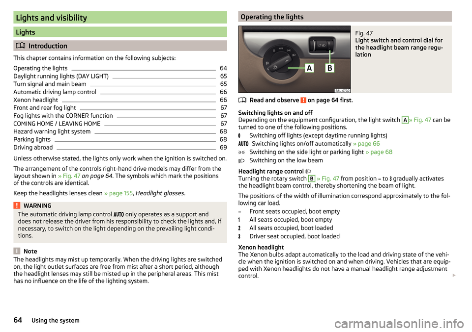
has no influence on the life of the lighting system.Operating the lightsFig. 47
Light switch and control dial for
the headlight beam range regu-
lation
Read and observe on page 64 first.
Switching lights on and off
Depending on the equipment configuration, the light switch
A
» Fig. 47 can be
turned to one of the following positions.
Switching off lights (except daytime running lights)Switching lights on/off automatically » page 66
Switching on the side light or parking light » page 68
Switching on the low beam
Headlight range control
Turning the rotary switch
B
» Fig. 47 from position
to
gradually activates
the headlight beam control, thereby shortening the beam of light.
The positions of the width of illumination correspond approximately to the fol- lowing car load.
Front seats occupied, boot empty
All seats occupied, boot empty
All seats occupied, boot loaded
Driver seat occupied, boot loaded
Xenon headlight
The Xenon bulbs adapt automatically to the load and driving state of the vehi-
cle when the ignition is switched on and when driving. Vehicles that are equip-
ped with Xenon headlights do not have a manual headlight range adjustment
control.
64Using the system
Page 67 of 232
WARNINGAlways adjust the headlight beam to meet the following conditions.■The vehicle does not dazzle other road users, especially oncoming vehi-
cles.■
The beam range is sufficient for safe driving.
Note
■ The light switch is in position or and the ignition is turned off, the low
beam is switched off automatically 1)
and the status light is lit. The side light is
switched off when the ignition key is removed, for vehicles with the KESSY
system after switching off the ignition and opening the driver's door.■
If there is a fault in the light switch, the low beam comes on automatically.
Daylight running lights (DAY LIGHT)
Read and observe
on page 64 first.
The daytime running light (hereinafter referred to as "function") lights the
front and rear vehicle area (only valid for some countries).
The daytime running lights are switched on automatically if the following
conditions are met.
The light switch is in the position
or
.
The ignition is switched on.
The function is activated.
Function for vehicles with MAXI DOT display disable / enable
The function menu item
Dayt. r. light
can be deactivated / activated » page 47,
Menu item
Settings
.
Disable function for vehicles with segment display
›
Switch off the ignition.
›
Pull the indicator / main beam lever towards the steering wheel, push down
and hold in this position.
›
Switch on the ignition.
›
Hold the lever in this position for min. 3 seconds after switching on the igni-
tion.
The deactivation of the function is confirmed by an audible signal.
Enable function for vehicles with segment display›Switch off the ignition.›
Pull the indicator / main beam lever towards the steering wheel, push up and
hold in this position.
›
Switch on the ignition.
›
Hold the lever in this position for min. 3 seconds after switching on the igni-
tion.
The activation of the function is confirmed by an audible signal.
WARNINGAlways switch on the low beam when visibility is poor.
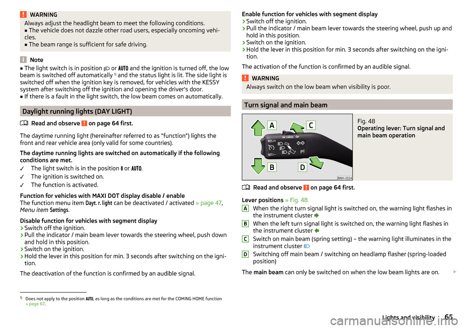
Turn signal and main beam
Fig. 48
Operating lever: Turn signal and
main beam operation
Read and observe on page 64 first.
Lever positions » Fig. 48
When the right turn signal light is switched on, the warning light flashes in
the instrument cluster
When the left turn signal light is switched on, the warning light flashes in
the instrument cluster
Switch on main beam (spring setting) – the warning light illuminates in the
instrument cluster
Switching off main beam / switching on headlamp flasher (spring-loaded position)
The main beam can only be switched on when the low beam lights are on.
ABCD1)
Does not apply to the position
, as long as the conditions are met for the COMING HOME function
» page 67 .
65Lights and visibility
Page 68 of 232
The headlight flasher can be operated even if the ignition is switched off.
The turn signal light switches itself off automatically when driving around a
curve or after making a turn.
“Convenience turn signal”
When the control lever is lightly pressed to the pressure point A
or
B
then
the respective turn-signal lamp flashes three times.
The “Lane ch. flash” can be activated / deactivated via the Maxi DOT display in
the
Lane ch. flash
» page 47 , Menu item
Settings
menu item.
WARNINGOnly turn on the main beam or the headlight flasher if other road users will
not be dazzled.
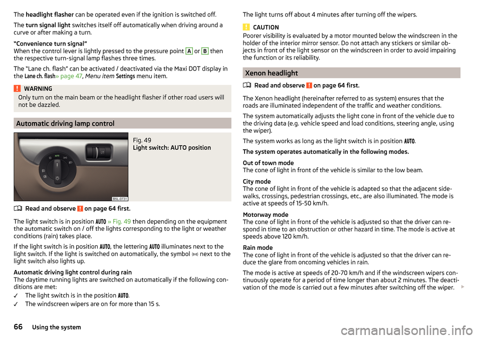
Automatic driving lamp control
Fig. 49
Light switch: AUTO position
Read and observe on page 64 first.
The light switch is in position
» Fig. 49 then depending on the equipment
the automatic switch on / off the lights corresponding to the light or weather
conditions (rain) takes place.
If the light switch is in position
, the lettering
illuminates next to the
light switch. If the light is switched on automatically, the symbol
next to the
light switch also lights up.
Automatic driving light control during rain
The daytime running lights are switched on automatically if the following con-
ditions are met:
The light switch is in the position
.
The windscreen wipers are on for more than 15 s.
The light turns off about 4 minutes after turning off the wipers.
CAUTION
Poorer visibility is evaluated by a motor mounted below the windscreen in the
holder of the interior mirror sensor. Do not attach any stickers or similar ob-
jects in front of the light sensor on the windscreen in order to avoid impairing
the function or its reliability.
Xenon headlight
Read and observe
on page 64 first.
The Xenon headlight (hereinafter referred to as system) ensures that the
roads are illuminated independent of the traffic and weather conditions.
The system automatically adjusts the light cone in front of the vehicle due to
the driving data (e.g. vehicle speed and load conditions, steering angle, using
the wiper).
The system works as long as the light switch is in position .
The system operates automatically in the following modes.
Out of town mode
The cone of light in front of the vehicle is similar to the low beam.
City mode
The cone of light in front of the vehicle is adapted so that the adjacent side-
walks, crossings, pedestrian crossings, etc., are also illuminated. The mode is
active at speeds of 15-50 km/h.
Motorway mode
The cone of light in front of the vehicle is adjusted so that the driver can re-
spond in time to an obstruction or other hazard in time. The mode is active at
speeds above 120 km/h.
Rain mode
The cone of light in front of the vehicle is adjusted so that the driver can re-
duce the glare from oncoming vehicles in rain.
The mode is active at speeds of 20-70 km/h and if the windscreen wipers con-
tinuously operate for a period of time longer than about 2 minutes. The deacti-
vation of the mode is carried out a few minutes after switching off the wiper.
66Using the system
Page 75 of 232
Automatic rear window wiping can be activated / deactivated via the MAXI
DOT display in the menu item Rear wiper
» page 47 .WARNINGAutomatic wiping during rain is only a support. The driver is not released
from the responsibility to set the function of the windscreen wipers man-
ually depending on the visibility conditions.
Note
■ If the operating lever is in the position 2 or 3 and the speed of the vehicle
drops below 4 km / h, the wiping speed is reduced. The original wiping speed is
restored step by step when the speed of the vehicle exceeds 8 km/h.■
The rear window is wiped once automatically if the windscreen wipers are on
when reverse gear is selected.
Headlight cleaning system
Read and observe
and on page 71 first.
To clean the headlights, the headlamp is also sprayed after every five squirts.The headlight washer system works under the following conditions. The ignition is switched on.
The low beam is switched on.
The outside temperature is about -12° C to +39° C.
To ensure the correct functioning of the system, even in winter, this needs to be regularly cleared of snow and ice, e.g. free with a de-icing spray.
CAUTION
Never remove the nozzles from the headlight cleaning system by hand – risk of
damage!
Rear mirror
Introduction
This chapter contains information on the following subjects:
Interior mirror dimming
73
Exterior mirrors
74WARNING■ Convex (curved outward) or aspheric exterior mirrors increase the field of
vision. They do, however, make objects appear smaller in the mirror. These
mirrors are therefore only of limited use for estimating distances to the fol-
lowing vehicles.■
Whenever possible use the interior mirror for estimating the distances to
the following vehicles.
WARNINGThe mirrors with automatic dimming contain an electrolyte liquid which can
escape if mirror glass is broken.■
The leaking electrolytic fluid can irritate the skin, eyes and breath appara-
tus.
■
If your eyes or skin come into contact with the electrolytic fluid, immedi-
ately wash the affected area for a few minutes long with a lot of water. If
necessary get medical assistance.
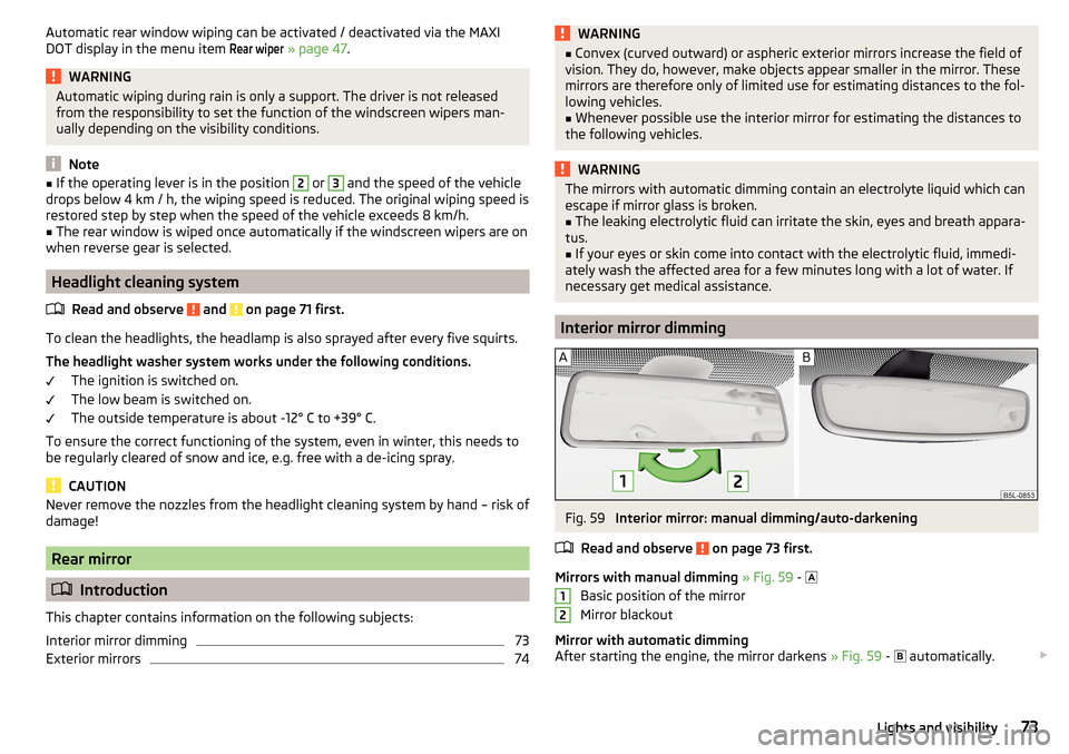
Interior mirror dimming
Fig. 59
Interior mirror: manual dimming/auto-darkening
Read and observe
on page 73 first.
Mirrors with manual dimming » Fig. 59 -
Basic position of the mirror
Mirror blackout
Mirror with automatic dimming
After starting the engine, the mirror darkens » Fig. 59 -
automatically.
1273Lights and visibility
Page 78 of 232
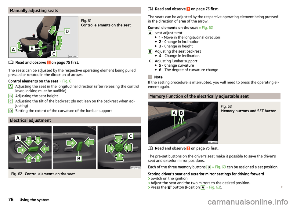
Manually adjusting seatsFig. 61
Control elements on the seat
Read and observe on page 75 first.
The seats can be adjusted by the respective operating element being pulledpressed or rotated in the direction of arrows.
Control elements on the seat » Fig. 61
Adjusting the seat in the longitudinal direction (after releasing the control
lever, locking must be audible)
Adjusting the seat height
Adjusting the tilt of the backrest (do not lean on the backrest when ad-
justing)
Setting the extent of the curvature of the lumbar support
Electrical adjustment
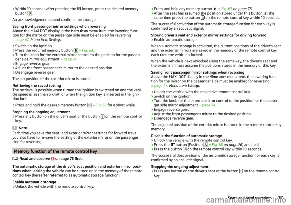
Fig. 62
Control elements on the seat
ABCDRead and observe on page 75 first.
The seats can be adjusted by the respective operating element being pressed in the direction of area of the arrow.
Control elements on the seat » Fig. 62
seat adjustment
▶ 1 - Move in the longitudinal direction
▶ 2 - Change in inclination
▶ 3 - Change in height
Adjusting the seat backrest
▶ 4 - Change in inclination
Adjusting lumbar support
▶ 5 - Change curvature
▶ 6 - The degree of curvature change
Note
If the setting procedure is interrupted, you will need to press the operating el-
ement again.
Memory Function of the electrically adjustable seat
Fig. 63
Memory buttons and SET button
Read and observe on page 75 first.
The pre-set buttons on the driver's seat make it possible to save the driver's seat and exterior mirror positions.
Each of the three memory buttons
B
» Fig. 63 can be assigned a set position.
Storing driver's seat and exterior mirror settings for driving forward
›
Switch on the ignition.
›
Adjust the seat and the two mirrors to the desired position.
›
Press the
button (Position
A
» Fig. 63 ).
ABC76Using the system
Page 79 of 232
›Within 10 seconds after pressing the
button, press the desired memory
button B.
An acknowledgement sound confirms the storage.
Saving front passenger mirror settings when reversing
Above the MAXI DOT display in the
Mirror down
menu item, the lowering func-
tion for the mirror on the passenger side must be enabled for reversing
» page 47 , Menu item
Settings
.
›
Switch on the ignition.
›
Press the required memory button
B
» Fig. 63 .
›
Turn the knob for the external mirror control to the position for the passen-
ger side mirror adjustment » page 74.
›
Engage reverse gear.
›
Adjust the front passenger's mirror to the desired position.
›
Disengage reverse gear.
The set position of the exterior mirror is stored.
Retrieving the saved setting
The retrieval is possible when turned the ignition is switched on and the vehi-
cle speed is less than 5 km/h or when the ignition key is inserted in the igni-
tion lock.
›
Press and hold the desired memory button
B
» Fig. 63 for a short while.
Stopping the ongoing adjustment
›
Press any button on the driver's seat or the button on the remote control
key.
Note
Each time you save the seat- and exterior mirror settings for forward travel
you also have to re-save the setting of the exterior mirror on the passenger
side for reversing.
Memory function of the remote control key
Read and observe
on page 75 first.
The automatic storage of the driver's seat position and exterior mirror posi-tions when locking the vehicle can be turned on in the memory of the remote
control key (hereafter referred to as automatic storage function).
Enable automatic storage
›
Unlock the vehicle with the remote control key.
› Press and hold any memory button B
» Fig. 63 on page 76 .›After the seat has assumed the position stored under this button, at the
same time press the button on the remote control key within 10 seconds.
The successful activation of the automatic storage function for each key is
confirmed by an acoustic signal.
Storing driver's seat and exterior mirror settings for driving forward
›
Enable automatic storage.
When automatic storage is activated, the current positions of the driver's seat
and the external mirrors are saved in the memory of the remote control key
each time the vehicle is locked.
When the vehicle is next unlocked using the same key, the driver's seat and
the external mirrors assume the positions stored in the memory of this key.
Saving front passenger mirror settings when reversing
Above the MAXI DOT display in the
Mirror down
menu item, the lowering func-
tion for the mirror on the passenger side must be enabled for reversing
» page 47 , Menu item
Settings
.
›
Unlock the vehicle with the respective remote control key.
›
Switch on the ignition.
›
Turn the knob for the external mirror control to the position for the passen-
ger side mirror adjustment » page 74.
›
Engage reverse gear.
›
Adjust the front passenger's mirror to the desired position.
›
Disengage reverse gear.
The adjusted position of the exterior mirror is stored in the remote control key
memory.
Disable the function of automatic storage
›
Unlock the vehicle with the remote control key.
›
Press the button (Position
A
» Fig. 63 on page 76 ) and hold.
›
Press the button on the remote control key within 10 seconds.
The successful deactivation of the automatic storage function for each key is confirmed by an acoustic signal.
Stopping the ongoing adjustment
›
Press any button on the driver's seat or the button on the remote control
key.
77Seats and head restraints