ESP SKODA YETI 2015 1.G / 5L Owner's Guide
[x] Cancel search | Manufacturer: SKODA, Model Year: 2015, Model line: YETI, Model: SKODA YETI 2015 1.G / 5LPages: 232, PDF Size: 30.84 MB
Page 92 of 232
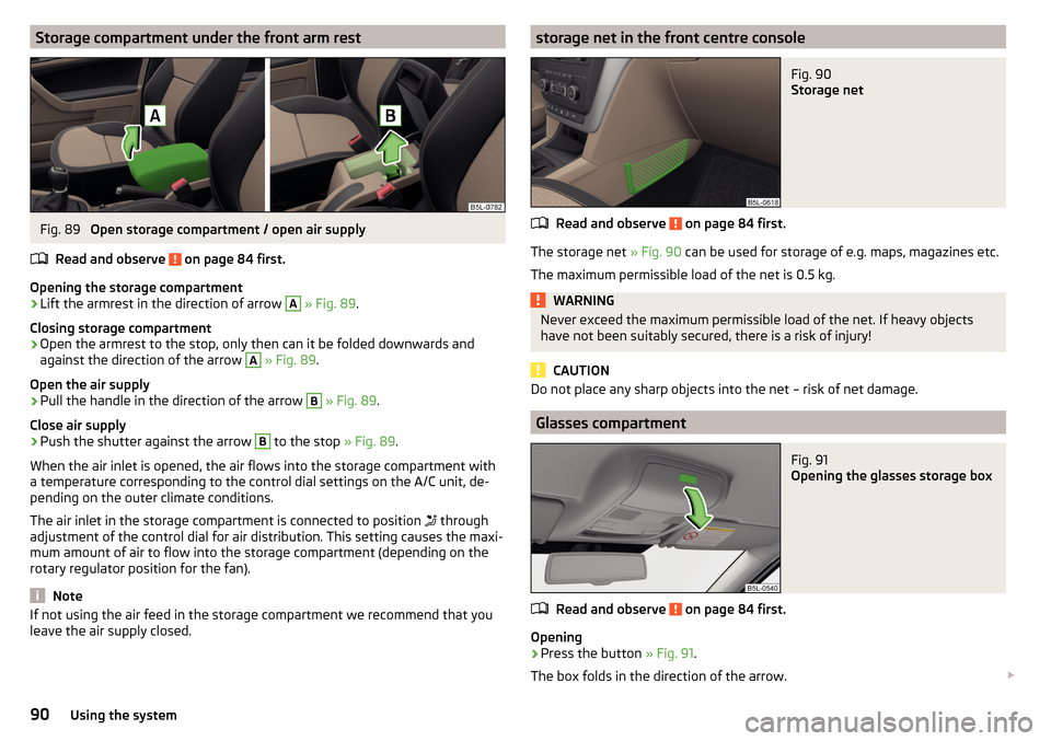
Storage compartment under the front arm restFig. 89
Open storage compartment / open air supply
Read and observe
on page 84 first.
Opening the storage compartment
›
Lift the armrest in the direction of arrow
A
» Fig. 89 .
Closing storage compartment
›
Open the armrest to the stop, only then can it be folded downwards and
against the direction of the arrow
A
» Fig. 89 .
Open the air supply
›
Pull the handle in the direction of the arrow
B
» Fig. 89 .
Close air supply
›
Push the shutter against the arrow
B
to the stop » Fig. 89.
When the air inlet is opened, the air flows into the storage compartment with
a temperature corresponding to the control dial settings on the A/C unit, de-
pending on the outer climate conditions.
The air inlet in the storage compartment is connected to position through
adjustment of the control dial for air distribution. This setting causes the maxi-
mum amount of air to flow into the storage compartment (depending on the
rotary regulator position for the fan).
Note
If not using the air feed in the storage compartment we recommend that you
leave the air supply closed.storage net in the front centre consoleFig. 90
Storage net
Read and observe on page 84 first.
The storage net » Fig. 90 can be used for storage of e.g. maps, magazines etc.
The maximum permissible load of the net is 0.5 kg.
WARNINGNever exceed the maximum permissible load of the net. If heavy objects
have not been suitably secured, there is a risk of injury!
CAUTION
Do not place any sharp objects into the net – risk of net damage.
Glasses compartment
Fig. 91
Opening the glasses storage box
Read and observe on page 84 first.
Opening
›
Press the button » Fig. 91.
The box folds in the direction of the arrow.
90Using the system
Page 98 of 232
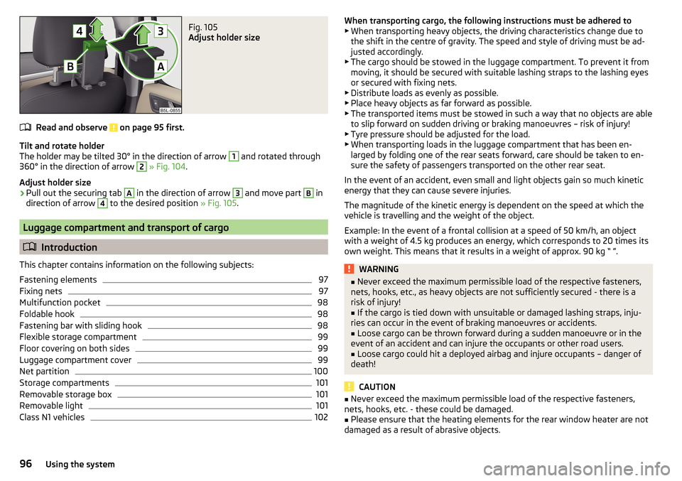
Fig. 105
Adjust holder size
Read and observe on page 95 first.
Tilt and rotate holder
The holder may be tilted 30° in the direction of arrow
1
and rotated through
360° in the direction of arrow
2
» Fig. 104 .
Adjust holder size
›
Pull out the securing tab
A
in the direction of arrow
3
and move part
B
in
direction of arrow
4
to the desired position » Fig. 105.
Luggage compartment and transport of cargo
Introduction
This chapter contains information on the following subjects:
Fastening elements
97
Fixing nets
97
Multifunction pocket
98
Foldable hook
98
Fastening bar with sliding hook
98
Flexible storage compartment
99
Floor covering on both sides
99
Luggage compartment cover
99
Net partition
100
Storage compartments
101
Removable storage box
101
Removable light
101
Class N1 vehicles
102When transporting cargo, the following instructions must be adhered to ▶ When transporting heavy objects, the driving characteristics change due to
the shift in the centre of gravity. The speed and style of driving must be ad-
justed accordingly.
▶ The cargo should be stowed in the luggage compartment. To prevent it from
moving, it should be secured with suitable lashing straps to the lashing eyes
or secured with fixing nets.
▶ Distribute loads as evenly as possible.
▶ Place heavy objects as far forward as possible.
▶ The transported items must be stowed in such a way that no objects are able
to slip forward on sudden driving or braking manoeuvres – risk of injury!
▶ Tyre pressure should be adjusted for the load.
▶ When transporting loads in the luggage compartment that has been en-
larged by folding one of the rear seats forward, care should be taken to en-
sure the safety of passengers transported on the other rear seat.
In the event of an accident, even small and light objects gain so much kinetic
energy that they can cause severe injuries.
The magnitude of the kinetic energy is dependent on the speed at which the
vehicle is travelling and the weight of the object.
Example: In the event of a frontal collision at a speed of 50 km/h, an object
with a weight of 4.5 kg produces an energy, which corresponds to 20 times its
own weight. This means that it results in a weight of approx. 90 kg “ ”.WARNING■ Never exceed the maximum permissible load of the respective fasteners,
nets, hooks, etc., as heavy objects are not sufficiently secured - there is a
risk of injury!■
If the cargo is tied down with unsuitable or damaged lashing straps, inju-
ries can occur in the event of braking manoeuvres or accidents.
■
Loose cargo can be thrown forward during a sudden manoeuvre or in the
event of an accident and can injure the occupants or other road users.
■
Loose cargo could hit a deployed airbag and injure occupants – danger of
death!
CAUTION
■ Never exceed the maximum permissible load of the respective fasteners,
nets, hooks, etc. - these could be damaged.■
Please ensure that the heating elements for the rear window heater are not
damaged as a result of abrasive objects.
96Using the system
Page 107 of 232
WARNING■For your own safety and that of other road users, ensure that all the win-
dows are free of ice, snow and misting. The blower should always be on to
prevent the windows from misting up.■
Under certain circumstances, air at a temperature of about 5 °C can flow
out of the vents when the cooling system is switched on.
CAUTION
■ The air inlet in front of the windscreen must be free of e.g. ice, snow or
leaves to ensure that the heating and cooling system operates properly.■
After switching on the cooling Condensation from the evaporator of the air
conditioning may drip down and form a puddle below the vehicle. This is not a
leak!
■
If the coolant temperature is too high, the cooling system is switched off to
ensure that the engine cools down.
Heating and manual air conditioning
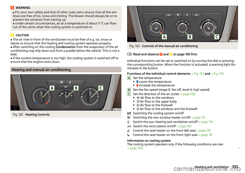
Fig. 122
Heating Controls
Fig. 123
Controls of the manual air conditioning
Read and observe
and on page 105 first.
Individual functions can be set or switched on by turning the dial or pressing the corresponding button. When the function is activated, a warning light illu-
minates in the button.
Functions of the individual control elements » Fig. 122 and » Fig. 123
Set the temperature
▶ Lower the temperature
▶ Increase the temperature
Set the fan speed (stage 0: fan off, level 4: high speed)
Set the direction of the air outlet » page 108
▶ Air flow to the windows
▶ Air flow to the upper body
▶ Air flow to the footwell
▶ Air flow to the windows and the footwell
Switching the cooling system on/off
Switching the rear window heater on/off » page 70
Switch the aux. heating and ventilation on/off » page 110
Switch the recirculation on/off » page 107
Control the seat heater on the front left seat » page 78
Control the seat heater on the front right seat » page 78
Information on cooling system
The cooling system operates only if the following conditions are met
» page 104 .
ABC105Heating and ventilation
Page 108 of 232
The warning light in the button » Fig. 123 illuminates after activation, even
if not all of the conditions for the function of the cooling system have been
met. By lighting up of the indicator light in the button, the operational readi-
ness of the cooling system is signalled.
Note
During operation of the manual air conditioning, an increase in engine idle
speed may occur under certain circumstances in order to ensure sufficient
heating comfort.
Climatronic (automatic air conditioning)
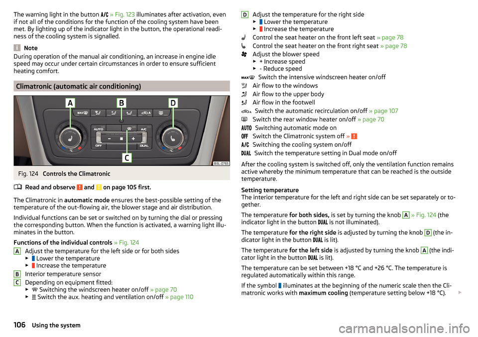
Fig. 124
Controls the Climatronic
Read and observe
and on page 105 first.
The Climatronic in automatic mode ensures the best-possible setting of the
temperature of the out-flowing air, the blower stage and air distribution.
Individual functions can be set or switched on by turning the dial or pressing
the corresponding button. When the function is activated, a warning light illu-
minates in the button.
Functions of the individual controls » Fig. 124
Adjust the temperature for the left side or for both sides
▶ Lower the temperature
▶ Increase the temperature
Interior temperature sensor
Depending on equipment fitted:
▶ Switching the windscreen heater on/off
» page 70
▶ Switch the aux. heating and ventilation on/off
» page 110
ABCAdjust the temperature for the right side
▶ Lower the temperature
▶ Increase the temperature
Control the seat heater on the front left seat » page 78
Control the seat heater on the front right seat » page 78
Adjust the blower speed ▶ + Increase speed
▶ - Reduce speed
Switch the intensive windscreen heater on/off
Air flow to the windows
Air flow to the upper body
Air flow in the footwell Switch the automatic recirculation on/off » page 107
Switch the rear window heater on/off » page 70
Switching automatic mode on
Switch the Climatronic system off »
Switching the cooling system on/off
Switch the temperature setting in Dual mode on/off
After the cooling system is switched off, only the ventilation function remains
active whereby the minimum temperature that can be reached is the outside
temperature.
Setting temperature
The interior temperature for the left and right side can be set separately or to-
gether.
The temperature for both sides, is set by turning the knob
A
» Fig. 124 (the
indicator light in the button is not illuminated).
The temperature for the right side is adjusted by turning the knob
D
(the in-
dicator light in the button is lit).
The temperature for the left side is adjusted by turning the knob
A
(the indi-
cator light in the button is lit).
The temperature can be set between +18 °C and +26 °C. The temperature is
regulated automatically within this range.
If the symbol illuminates at the beginning of the numeric scale then the Cli-
matronic works with maximum cooling (temperature setting below +18 °C).
D106Using the system
Page 115 of 232
Driving
Starting-off and Driving
Starting and stopping the engine using the key
Introduction
This chapter contains information on the following subjects:
Electronic immobilizer
113
Steering lock locking / unlocking
114
Turn ignition on / off and start the engine
114
Stopping the engine
114
With the key in the ignition, the ignition can be switched on and off and the
engine can be started / stopped.
WARNING■ While driving with the engine stopped, the ignition must always be
switched on » page 114, Turn ignition on / off and start the engine .
■ With the ignition off, the steering may lock » page 114 - danger of an
accident!■
Do not withdraw the ignition key from the ignition lock until the vehicle
has come to a stop » page 121, Parking . Otherwise, the steering may lock -
danger of an accident!
■
Never leave the key in the vehicle when you exit the vehicle. Unauthor-
ized persons, such as children, for example, could lock the car, turn on the
ignition or start the engine - there is a danger of injury, damage and acci-
dents!
■
Never leave the vehicle unattended with the engine running - there is
risk of accident, damage or theft!
■
Never switch off the engine before the vehicle is stationary – risk of acci-
dent!
WARNING■ Never (e.g. in garages) run the engine in a closed place - there is the dan-
ger of poisoning and death!■
Do not leave any items (e.g. cloths or tools) in the engine compartment.
This presents a fire hazard and the risk of engine damage.
■
Never cover the engine with additional insulation material (e.g. with a
cover) – risk of fire!
CAUTION
■ Only start the engine when the engine and the vehicle are stationary - there
is a danger of starter and engine damage!■
Do not push-start the engine – risk of damaging the engine and the catalytic
converter. The battery from another vehicle can be used as a jump-start aid
» page 189 .
Note
Do not warm up the engine while the vehicle is stationary. If possible, start
your journey as soon as the engine has started. Through this, the engine rea-
ches its operating temperature faster.
Electronic immobilizer
Read and observe
and on page 113 first.
The electronic immobiliser (hereinafter referred to as immobiliser) makes the
attempted theft or unauthorised use of your vehicle more difficult.
An electronic chip is integrated in the head of the key. The immobiliser is deac-
tivated with the aid of this chip when the key is inserted in the ignition lock.
As soon as the ignition key is removed from the ignition lock, the immobiliser is
automatically activated.
Operational problems
If a component in the immobiliser key fails, it is not possible to start the en-
gine. A corresponding message appears in the display of the instrument clus-
ter to explain the immobiliser is active.
To start, use the other vehicle key or seek help from a specialist garage.
113Starting-off and Driving
Page 123 of 232
ParkingRead and observe
and on page 119 first.
When stopping and parking, look for a place with a suitable surface » .
Only carry out the activities while parking in the specified order.
›
Bring the vehicle to a stop and depress the brake pedal.
›
Firmly apply the handbrake.
›
On vehicles with automatic transmission place the selector lever in the P po-
sition.
›
Switch off the engine.
›
For vehicles with Manual transmission select the 1st gear or the Reverse
gear R .
›
Release the brake pedal.
WARNINGThe exhaust system components can become very hot. Therefore, never
stop the vehicle at places where the underside of your vehicle can come in-
to contact with flammable materials such as dry grass, undergrowth,
leaves, spilled fuel or such like. - Risk of fire and serious injury can occur!
Manual gear changing and pedals
Introduction
This chapter contains information on the following subjects:
Manual gear changing
121
Pedals
121
Manual gear changing
Fig. 135
Gearshift pattern of 5 gear or
6 gear manual gearbox
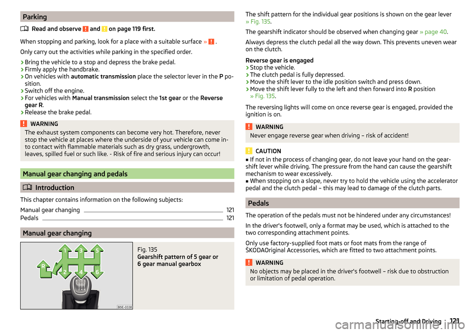
The shift pattern for the individual gear positions is shown on the gear lever » Fig. 135 .
The gearshift indicator should be observed when changing gear » page 40.
Always depress the clutch pedal all the way down. This prevents uneven wear
on the clutch.
Reverse gear is engaged›
Stop the vehicle.
›
The clutch pedal is fully depressed.
›
Move the shift lever to the idle position switch and press down.
›
Move the shift lever fully to the left and then forward into R position
» Fig. 135 .
The reversing lights will come on once reverse gear is engaged, provided the
ignition is on.
WARNINGNever engage reverse gear when driving – risk of accident!
CAUTION
■ If not in the process of changing gear, do not leave your hand on the gear-
shift lever while driving. The pressure from the hand can cause the gearshift
mechanism to wear excessively.■
When stopping on a slope, never try to hold the vehicle using the accelerator
pedal and the clutch pedal – this may lead to damage of the clutch parts.
Pedals
The operation of the pedals must not be hindered under any circumstances!
In the driver's footwell, only a format may be used, which is attached to the
two corresponding attachment points.
Only use factory-supplied foot mats or foot mats from the range of
ŠKODAOriginal Accessories, which are fitted to two attachment points.
WARNINGNo objects may be placed in the driver's footwell – risk due to obstruction
or limitation of pedal operation.121Starting-off and Driving
Page 127 of 232
New tyres
New tyres must firstly be “run in”, as they do not offer optimal grip at first.
Therefore, drive especially carefully for the first 500 km or so.
New brake pads
New brake pads have to first “grind in” because these do not initially have the
best possible braking effect.
Therefore, drive especially carefully for the first 200 km or so.
Tips for economical driving
To achieve the lowest possible fuel consumption, the following instructions
must be observed.
Looking ahead when driving
Avoid unnecessary acceleration and braking.
Switch in an energy saving and timely manner Observe the recommended gear » page 40.
Avoid full throttle and high speeds
Fuel consumption can be reduced by half if only three-quarters of the possible
top speed of your vehicle is used.
Reducing idling
If the vehicle is fitted with the START - STOP system there is an automatic re-
duction of the idling. If the engine is stopped on vehicles without START-STOP
system, such as when waiting in a traffic jam, the fuel economy is already
greater after 30 - 40 s than the fuel quantity which is required for engine re-
start.
Avoid short distances
When driving a short distance of less than about 4 km, the engine cannot
reach its operating temperature. As long as the engine has not reached oper-
ating temperature, the fuel consumption is significantly higher than with the
engine hot.
Pay attention to the correct tyre inflation pressure being maintained
Further information » page 176.
Avoid unnecessary ballast
Per 100 kg of weight, consumption increases by about 0.3 l/100 km. At a speed
of 100 - 120 km/h, a vehicle fitted with a roof rack cross member without a load
will use about 10 % more fuel than normal due to the increased aerodynamic
drag.
Saving electricity
Only turn on electrical consumers (e.g. seat, window and mirror heating, etc.)
for as long as necessary.
Use the cooling system economically
The air conditioning system compressor uses power from the engine when in
cooling mode, which will affect the fuel consumption.
It recommended to open the windows or the doors of a vehicle for which the
interior has been strongly heated through the effect of direct sunlight in order
to allow the heated air to escape.
The cooling system should not be on if the windows are open.
Avoiding damage to your vehicle
Introduction
This chapter contains information on the following subjects:
Driving Tips
125
Driving through water
126
This section of the manual contains important information on preventing dam-
age to the vehicle while driving.
Driving Tips
Only drive on such roads and in such terrain, which match the vehicle parame-
ters » page 204 , Technical data as well as your driving skills.
The driver is always responsible for deciding whether the vehicle can handle
travelling in the given terrain.
When travelling off paved roads, we recommend activating the OFF ROAD
mode » page 129 .
125Starting-off and Driving
Page 129 of 232
Assist systems
General information
Introduction
WARNINGThe following general information regarding the use of assistance systems
must be observed.■
The assistance systems only serve to support and do not relieve the driv-
er of the responsibility for driving the vehicle.
■
The increased safety provision, as well as the increased occupant protec-
tion provided by the assistance systems must not tempt you to take risks -
risk of accident!
■
Adjust the speed and driving style to the current visibility, weather, road
and traffic conditions.
■
The assistance systems have physical and system-related limitations. For
this reason, the driver may experience some undesired or delayed system
responses in certain situations. You should therefore always be alert and
ready to intervene!
■
Only activate, deactivate or set the assistance systems so that you have
the car fully under control in every traffic situation - risk of accident!
Braking and stabilisation systems
Introduction
This chapter contains information on the following subjects:
Stability Control (ESC)
127
Anti-lock braking system (ABS)
127
Traction control (TCS)
128
Electronic Differential Lock (EDL)
128
Driver Steering Recommendation (DSR)
128
Brake Assist (HBA)
128
Hill Start Assist (HHC)
128
Trailer stabilization system (TSA)
129
This chapter describes the functions of the brake and stabilization systems.
The error display is in Chapter » page 32, Warning lights .
The brake and stabilization systems are automatically activated each time the
ignition is switched on, unless otherwise indicated.WARNINGThe general information relating to the use of assistance systems must be
observed » page 127, in section Introduction .
Stability Control (ESC)
Fig. 140
Press the ESC system: Activat-
ing/deactivating TCS
Read and observe on page 127 first.
The ESC improves vehicle stability in dynamic driving situations, such as when
the vehicle starts to skid.
The ESC monitors whether the desired direction of the current vehicle motion
is occurring. In case of any deviation (e.g. over steer), the ESC automatically
brakes individual wheels to maintain the desired direction.
During an intervention of the system, the indicator light
flashes in the in-
strument cluster.
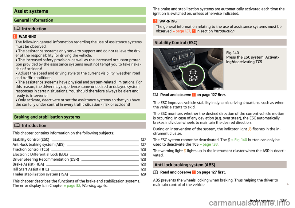
The ESC system cannot be deactivated. The
» Fig. 140 button can only be
used to deactivate the TCS » page 128.
The warning light
lights up in the instrument cluster when the ASR is deacti-
vated.
Anti-lock braking system (ABS)
Read and observe
on page 127 first.
ABS prevents the wheels locking when braking. Thus helping the driver to
maintain control of the vehicle.
127Assist systems
Page 130 of 232
The intervention of the ABS is noticeable from the pulsating movements of
the brake pedal which is accompanied by noises.
When the ABS system is active, do not brake periodically or reduce the pres- sure on the brake pedal.
Traction control (TCS)
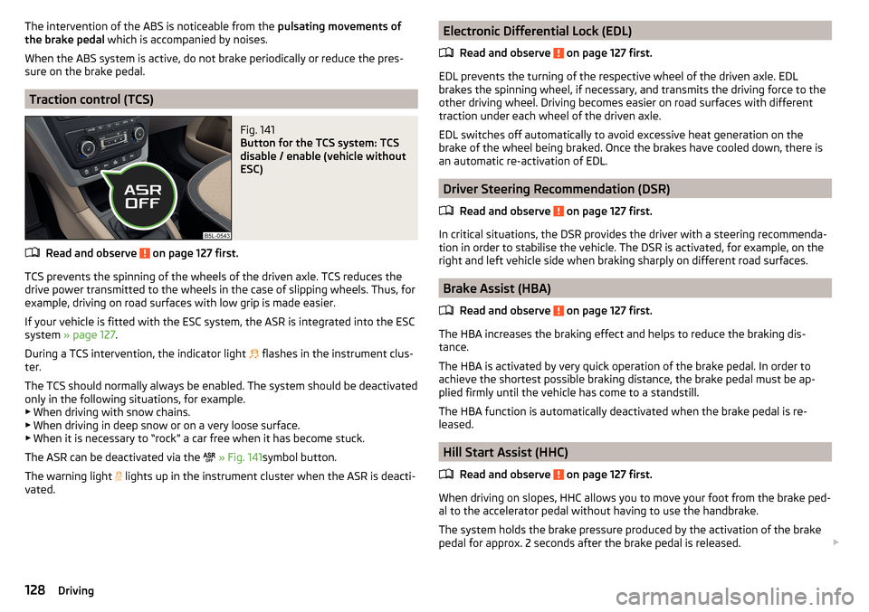
Fig. 141
Button for the TCS system: TCS
disable / enable (vehicle without
ESC)
Read and observe on page 127 first.
TCS prevents the spinning of the wheels of the driven axle. TCS reduces the
drive power transmitted to the wheels in the case of slipping wheels. Thus, for
example, driving on road surfaces with low grip is made easier.
If your vehicle is fitted with the ESC system, the ASR is integrated into the ESC
system » page 127 .
During a TCS intervention, the indicator light flashes in the instrument clus-
ter.
The TCS should normally always be enabled. The system should be deactivated
only in the following situations, for example. ▶ When driving with snow chains.
▶ When driving in deep snow or on a very loose surface.
▶ When it is necessary to “rock” a car free when it has become stuck.
The ASR can be deactivated via the
» Fig. 141 symbol button.
The warning light lights up in the instrument cluster when the ASR is deacti-
vated.
Electronic Differential Lock (EDL)
Read and observe
on page 127 first.
EDL prevents the turning of the respective wheel of the driven axle. EDL
brakes the spinning wheel, if necessary, and transmits the driving force to the
other driving wheel. Driving becomes easier on road surfaces with different
traction under each wheel of the driven axle.
EDL switches off automatically to avoid excessive heat generation on the
brake of the wheel being braked. Once the brakes have cooled down, there is
an automatic re-activation of EDL.
Driver Steering Recommendation (DSR)
Read and observe
on page 127 first.
In critical situations, the DSR provides the driver with a steering recommenda-
tion in order to stabilise the vehicle. The DSR is activated, for example, on the
right and left vehicle side when braking sharply on different road surfaces.
Brake Assist (HBA)
Read and observe
on page 127 first.
The HBA increases the braking effect and helps to reduce the braking dis-
tance.
The HBA is activated by very quick operation of the brake pedal. In order to
achieve the shortest possible braking distance, the brake pedal must be ap-
plied firmly until the vehicle has come to a standstill.
The HBA function is automatically deactivated when the brake pedal is re-
leased.
Hill Start Assist (HHC)
Read and observe
on page 127 first.
When driving on slopes, HHC allows you to move your foot from the brake ped-
al to the accelerator pedal without having to use the handbrake.
The system holds the brake pressure produced by the activation of the brake pedal for approx. 2 seconds after the brake pedal is released.
128Driving
Page 136 of 232
OperationFig. 147
Position of the camera / monitored area
Read and observe
and on page 133 first.
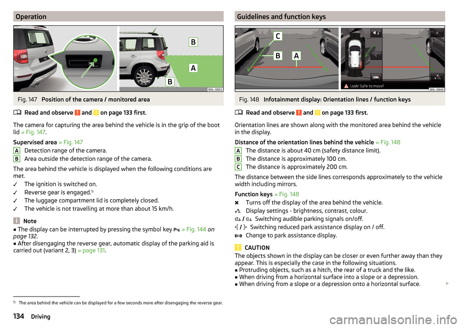
The camera for capturing the area behind the vehicle is in the grip of the boot
lid » Fig. 147 .
Supervised area » Fig. 147
Detection range of the camera.
Area outside the detection range of the camera.
The area behind the vehicle is displayed when the following conditions are
met.
The ignition is switched on.
Reverse gear is engaged. 1)
The luggage compartment lid is completely closed.
The vehicle is not travelling at more than about 15 km/h.
Note
■ The display can be interrupted by pressing the symbol key » Fig. 144 on
page 132 .■
After disengaging the reverse gear, automatic display of the parking aid is
carried out (variant 2, 3) » page 131.
ABGuidelines and function keysFig. 148
Infotainment display: Orientation lines / function keys
Read and observe
and on page 133 first.
Orientation lines are shown along with the monitored area behind the vehicle
in the display.
Distance of the orientation lines behind the vehicle » Fig. 148
The distance is about 40 cm (safety distance limit).
The distance is approximately 100 cm.
The distance is approximately 200 cm.
The distance between the side lines corresponds approximately to the vehicle width including mirrors.
Function keys » Fig. 148
Turns off the display of the area behind the vehicle.
Display settings - brightness, contrast, colour. Switching audible parking signals on/off.
Switching reduced park assistance display on / off.
Change to park assistance display.
CAUTION
The objects shown in the display can be closer or even further away than they
appear. This is especially the case in the following situations.■
Protruding objects, such as a hitch, the rear of a truck and the like.
■
When driving from a horizontal surface into a slope or a depression.
■
When driving from a slope or a depression onto a horizontal surface.
ABC
1)
The area behind the vehicle can be displayed for a few seconds more after disengaging the reverse gear.
134Driving