buttons SKODA YETI 2015 1.G / 5L Owner's Manual
[x] Cancel search | Manufacturer: SKODA, Model Year: 2015, Model line: YETI, Model: SKODA YETI 2015 1.G / 5LPages: 232, PDF Size: 30.84 MB
Page 29 of 232
Using the system
Cockpit
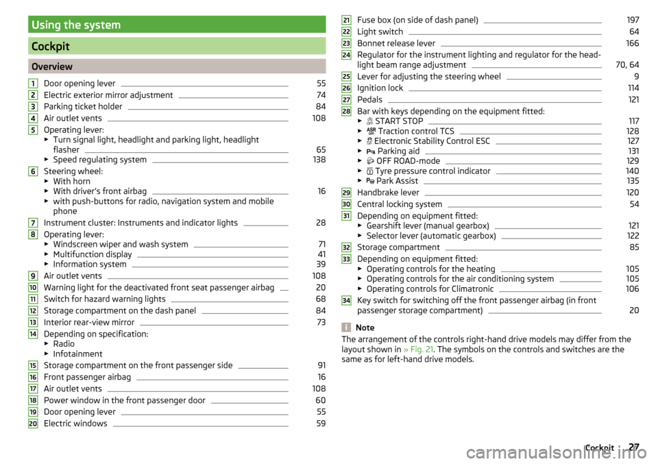
OverviewDoor opening lever
55
Electric exterior mirror adjustment
74
Parking ticket holder
84
Air outlet vents
108
Operating lever:
▶ Turn signal light, headlight and parking light, headlight
flasher
65
▶ Speed regulating system
138
Steering wheel:
▶ With horn
▶ With driver’s front airbag
16
▶with push-buttons for radio, navigation system and mobile
phone
Instrument cluster: Instruments and indicator lights
28
Operating lever:
▶ Windscreen wiper and wash system
71
▶Multifunction display
41
▶Information system
39
Air outlet vents
108
Warning light for the deactivated front seat passenger airbag
20
Switch for hazard warning lights
68
Storage compartment on the dash panel
84
Interior rear-view mirror
73
Depending on specification:
▶ Radio
▶ Infotainment
Storage compartment on the front passenger side
91
Front passenger airbag
16
Air outlet vents
108
Power window in the front passenger door
60
Door opening lever
55
Electric windows
591234567891011121314151617181920Fuse box (on side of dash panel)197
Light switch
64
Bonnet release lever
166
Regulator for the instrument lighting and regulator for the head-
light beam range adjustment
70, 64
Lever for adjusting the steering wheel
9
Ignition lock
114
Pedals
121
Bar with keys depending on the equipment fitted:
▶ START STOP
117
▶
Traction control TCS
128
▶
Electronic Stability Control ESC
127
▶
Parking aid
131
▶
OFF ROAD-mode
129
▶
Tyre pressure control indicator
140
▶
Park Assist
135
Handbrake lever
120
Central locking system
54
Depending on equipment fitted:
▶ Gearshift lever (manual gearbox)
121
▶Selector lever (automatic gearbox)
122
Storage compartment
85
Depending on equipment fitted:
▶ Operating controls for the heating
105
▶Operating controls for the air conditioning system
105
▶Operating controls for Climatronic
106
Key switch for switching off the front passenger airbag (in front
passenger storage compartment)
20
Note
The arrangement of the controls right-hand drive models may differ from the
layout shown in » Fig. 21. The symbols on the controls and switches are the
same as for left-hand drive models.212223242526272829303132333427Cockpit
Page 32 of 232
Fuel gaugeFig. 25
Fuel gauge
Read and observe on page 28 first.
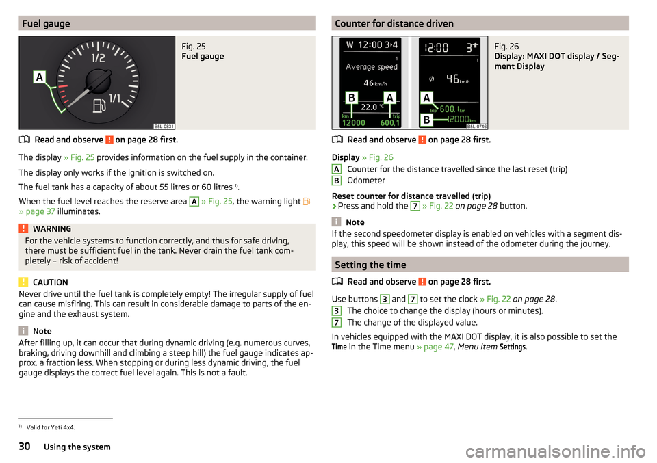
The display » Fig. 25 provides information on the fuel supply in the container.
The display only works if the ignition is switched on.
The fuel tank has a capacity of about 55 litres or 60 litres 1)
.
When the fuel level reaches the reserve area
A
» Fig. 25 , the warning light
» page 37 illuminates.
WARNINGFor the vehicle systems to function correctly, and thus for safe driving,
there must be sufficient fuel in the tank. Never drain the fuel tank com-
pletely – risk of accident!
CAUTION
Never drive until the fuel tank is completely empty! The irregular supply of fuel
can cause misfiring. This can result in considerable damage to parts of the en-
gine and the exhaust system.
Note
After filling up, it can occur that during dynamic driving (e.g. numerous curves,
braking, driving downhill and climbing a steep hill) the fuel gauge indicates ap-
prox. a fraction less. When stopping or during less dynamic driving, the fuel
gauge displays the correct fuel level again. This is not a fault.Counter for distance drivenFig. 26
Display: MAXI DOT display / Seg-
ment Display
Read and observe on page 28 first.
Display » Fig. 26
Counter for the distance travelled since the last reset (trip)
Odometer
Reset counter for distance travelled (trip)
›
Press and hold the
7
» Fig. 22 on page 28 button.
Note
If the second speedometer display is enabled on vehicles with a segment dis-
play, this speed will be shown instead of the odometer during the journey.
Setting the time
Read and observe
on page 28 first.
Use buttons
3
and
7
to set the clock » Fig. 22 on page 28 .
The choice to change the display (hours or minutes).
The change of the displayed value.
In vehicles equipped with the MAXI DOT display, it is also possible to set the
Time
in the Time menu » page 47, Menu item
Settings
.
AB371)
Valid for Yeti 4x4.
30Using the system
Page 43 of 232
Gear recommendation - segment display
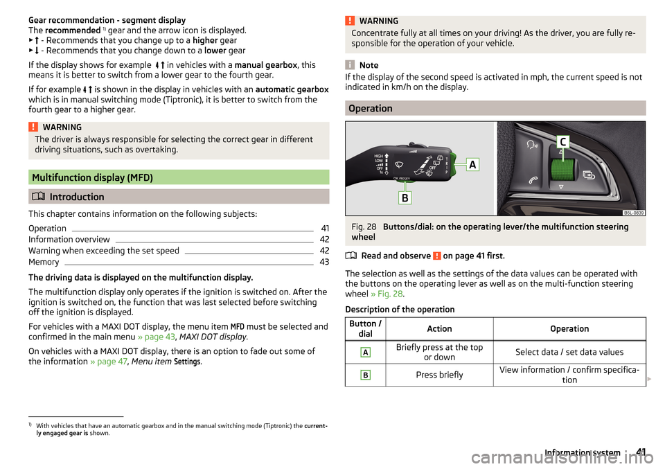
The recommended 1)
gear and the arrow icon is displayed.
▶ - Recommends that you change up to a higher gear
▶ - Recommends that you change down to a lower gear
If the display shows for example
in vehicles with a manual gearbox, this
means it is better to switch from a lower gear to the fourth gear.
If for example
is shown in the display in vehicles with an automatic gearbox
which is in manual switching mode (Tiptronic), it is better to switch from the
fourth gear to a higher gear.WARNINGThe driver is always responsible for selecting the correct gear in different
driving situations, such as overtaking.
Multifunction display (MFD)
Introduction
This chapter contains information on the following subjects:
Operation
41
Information overview
42
Warning when exceeding the set speed
42
Memory
43
The driving data is displayed on the multifunction display.
The multifunction display only operates if the ignition is switched on. After the ignition is switched on, the function that was last selected before switching
off the ignition is displayed.
For vehicles with a MAXI DOT display, the menu item
MFD
must be selected and
confirmed in the main menu » page 43, MAXI DOT display .
On vehicles with a MAXI DOT display, there is an option to fade out some of
the information » page 47, Menu item
Settings
.
WARNINGConcentrate fully at all times on your driving! As the driver, you are fully re-
sponsible for the operation of your vehicle.
Note
If the display of the second speed is activated in mph, the current speed is not
indicated in km/h on the display.
Operation
Fig. 28
Buttons/dial: on the operating lever/the multifunction steering
wheel
Read and observe
on page 41 first.
The selection as well as the settings of the data values can be operated with
the buttons on the operating lever as well as on the multi-function steering
wheel » Fig. 28 .
Description of the operation
Button / dialActionOperationABriefly press at the top or downSelect data / set data valuesBPress brieflyView information / confirm specifica- tion 1)
With vehicles that have an automatic gearbox and in the manual switching mode (Tiptronic) the
current-
ly engaged gear is shown.
41Information system
Page 46 of 232
Menu itemPhone46Menu item
Assistants46
Menu item
Settings47
Compass point display
48
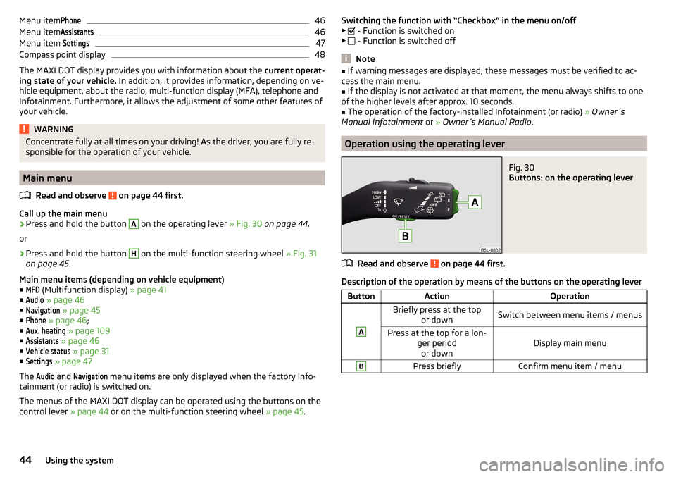
The MAXI DOT display provides you with information about the current operat-
ing state of your vehicle. In addition, it provides information, depending on ve-
hicle equipment, about the radio, multi-function display (MFA), telephone and
Infotainment. Furthermore, it allows the adjustment of some other features of
your vehicle.
WARNINGConcentrate fully at all times on your driving! As the driver, you are fully re-
sponsible for the operation of your vehicle.
Main menu
Read and observe
on page 44 first.
Call up the main menu
›
Press and hold the button
A
on the operating lever » Fig. 30 on page 44 .
or
›
Press and hold the button
H
on the multi-function steering wheel » Fig. 31
on page 45 .
Main menu items (depending on vehicle equipment) ■
MFD
(Multifunction display) » page 41
■
Audio
» page 46
■
Navigation
» page 45
■
Phone
» page 46 ;
■
Aux. heating
» page 109
■
Assistants
» page 46
■
Vehicle status
» page 31
■
Settings
» page 47
The
Audio
and
Navigation
menu items are only displayed when the factory Info-
tainment (or radio) is switched on.
The menus of the MAXI DOT display can be operated using the buttons on the
control lever » page 44 or on the multi-function steering wheel » page 45.
Switching the function with “Checkbox” in the menu on/off
▶ - Function is switched on
▶ - Function is switched off
Note
■
If warning messages are displayed, these messages must be verified to ac-
cess the main menu.■
If the display is not activated at that moment, the menu always shifts to one
of the higher levels after approx. 10 seconds.
■
The operation of the factory-installed Infotainment (or radio) » Owner´s
Manual Infotainment or » Owner´s Manual Radio .
Operation using the operating lever
Fig. 30
Buttons: on the operating lever
Read and observe on page 44 first.
Description of the operation by means of the buttons on the operating lever
ButtonActionOperationABriefly press at the top
or downSwitch between menu items / menusPress at the top for a lon- ger periodor downDisplay main menu
BPress brieflyConfirm menu item / menu44Using the system
Page 47 of 232
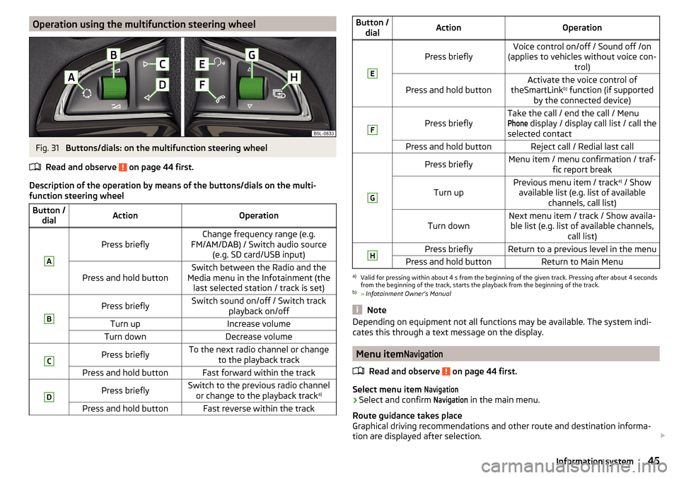
Operation using the multifunction steering wheelFig. 31
Buttons/dials: on the multifunction steering wheel
Read and observe
on page 44 first.
Description of the operation by means of the buttons/dials on the multi-
function steering wheel
Button / dialActionOperationA
Press brieflyChange frequency range (e.g.
FM/AM/DAB) / Switch audio source (e.g. SD card/USB input)Press and hold buttonSwitch between the Radio and the
Media menu in the Infotainment (the last selected station / track is set)BPress brieflySwitch sound on/off / Switch track playback on/offTurn upIncrease volumeTurn downDecrease volumeCPress brieflyTo the next radio channel or changeto the playback trackPress and hold buttonFast forward within the trackDPress brieflySwitch to the previous radio channelor change to the playback track a)Press and hold buttonFast reverse within the trackButton /
dialActionOperationE
Press brieflyVoice control on/off / Sound off /on
(applies to vehicles without voice con- trol)Press and hold buttonActivate the voice control of
theSmartLink b)
function (if supported
by the connected device)F
Press brieflyTake the call / end the call / MenuPhone
display / display call list / call the
selected contactPress and hold buttonReject call / Redial last callGPress brieflyMenu item / menu confirmation / traf- fic report breakTurn upPrevious menu item / track a)
/ Show
available list (e.g. list of available channels, call list)Turn downNext menu item / track / Show availa-ble list (e.g. list of available channels, call list)HPress brieflyReturn to a previous level in the menuPress and hold buttonReturn to Main Menua)
Valid for pressing within about 4 s from the beginning of the given track. Pressing after about 4 seconds
from the beginning of the track, starts the playback from the beginning of the track.
b)
» Infotainment Owner's Manual
Note
Depending on equipment not all functions may be available. The system indi-
cates this through a text message on the display.
Menu item
Navigation
Read and observe on page 44 first.
Select menu item
Navigation›
Select and confirm
Navigation
in the main menu.
Route guidance takes place
Graphical driving recommendations and other route and destination informa-
tion are displayed after selection.
45Information system
Page 60 of 232
WARNING■Never drive with the boot lid open or ajar, as otherwise exhaust gases
may get into the interior of the vehicle – risk of poisoning!■
Make sure that when closing the boot lid, no body parts are crushed -
there is danger of injury!
Opening/closing
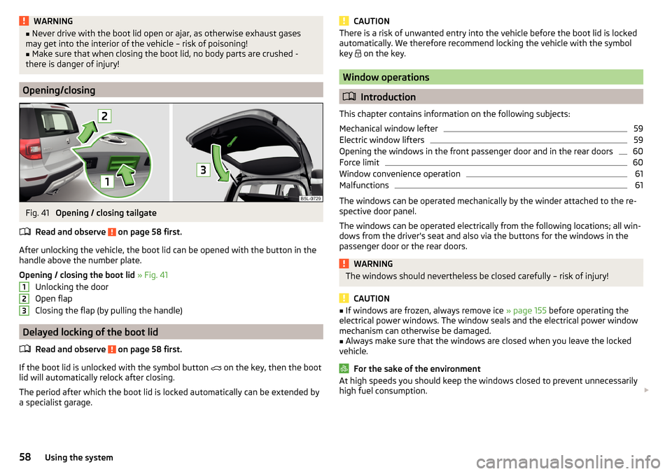
Fig. 41
Opening / closing tailgate
Read and observe
on page 58 first.
After unlocking the vehicle, the boot lid can be opened with the button in the
handle above the number plate.
Opening / closing the boot lid » Fig. 41
Unlocking the door
Open flap
Closing the flap (by pulling the handle)
Delayed locking of the boot lid
Read and observe
on page 58 first.
If the boot lid is unlocked with the symbol button on the key, then the boot
lid will automatically relock after closing.
The period after which the boot lid is locked automatically can be extended by
a specialist garage.
123CAUTIONThere is a risk of unwanted entry into the vehicle before the boot lid is locked
automatically. We therefore recommend locking the vehicle with the symbol
key
on the key.
Window operations
Introduction
This chapter contains information on the following subjects:
Mechanical window lefter
59
Electric window lifters
59
Opening the windows in the front passenger door and in the rear doors
60
Force limit
60
Window convenience operation
61
Malfunctions
61
The windows can be operated mechanically by the winder attached to the re-
spective door panel.
The windows can be operated electrically from the following locations; all win-
dows from the driver's seat and also via the buttons for the windows in the
passenger door or the rear doors.
WARNINGThe windows should nevertheless be closed carefully – risk of injury!
CAUTION
■ If windows are frozen, always remove ice » page 155 before operating the
electrical power windows. The window seals and the electrical power window
mechanism can otherwise be damaged.■
Always make sure that the windows are closed when you leave the locked
vehicle.
For the sake of the environment
At high speeds you should keep the windows closed to prevent unnecessarily high fuel consumption. 58Using the system
Page 61 of 232
NoteWhen driving always use the existing heating, air conditioning and ventilation
system for ventilating the interior of the vehicle. If the windows are opened,
dust as well as other dirt can get into the vehicle and in addition the wind
noise is more at certain speeds.
Mechanical window lefter
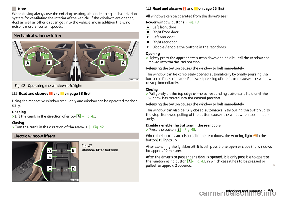
Fig. 42
Operating the window: left/right
Read and observe
and on page 58 first.
Using the respective window crank only one window can be operated mechan-
ically.
Opening
›
Lift the crank in the direction of arrow
A
» Fig. 42 .
Closing
›
Turn the crank in the direction of the arrow
B
» Fig. 42 .
Electric window lifters
Fig. 43
Window lifter buttons
Read and observe and on page 58 first.
All windows can be operated from the driver's seat.
Power window buttons » Fig. 43
Left front door
Right front door
Left rear door
Right rear door
Disable / enable the buttons in the rear doors
Opening
›
Lightly press the appropriate button down and hold it until the window has
moved into the desired position.
Releasing the button causes the window to halt immediately.
The window can be completely opened automatically by briefly pressing the
button as far as the stop. Renewed pressing of the button causes the window
to stop immediately.
Closing
›
Pull gently on the top edge of the corresponding button and hold until the
window has moved into the desired position.
Releasing the button causes the window to halt immediately.
The window can also be fully closed automatically by pulling the button up to
the stop. Renewed pulling of the button causes the window to stop immedi-
ately.
Disable / enable the buttons in the rear doors
›
Press the button
E
» Fig. 43 .
When the buttons are disabled in the rear doors, the warning light in the
button
E
lights up.
After switching the ignition off, it is still possible to open or close the windows
for approx. 10 minutes.
After the driver's or passenger's door is opened, it is only possible to operate
the window using button
A
» Fig. 43 , in which case it has to be pressed or
pulled for approx. 2 seconds.
ABCDE59Unlocking and opening
Page 65 of 232
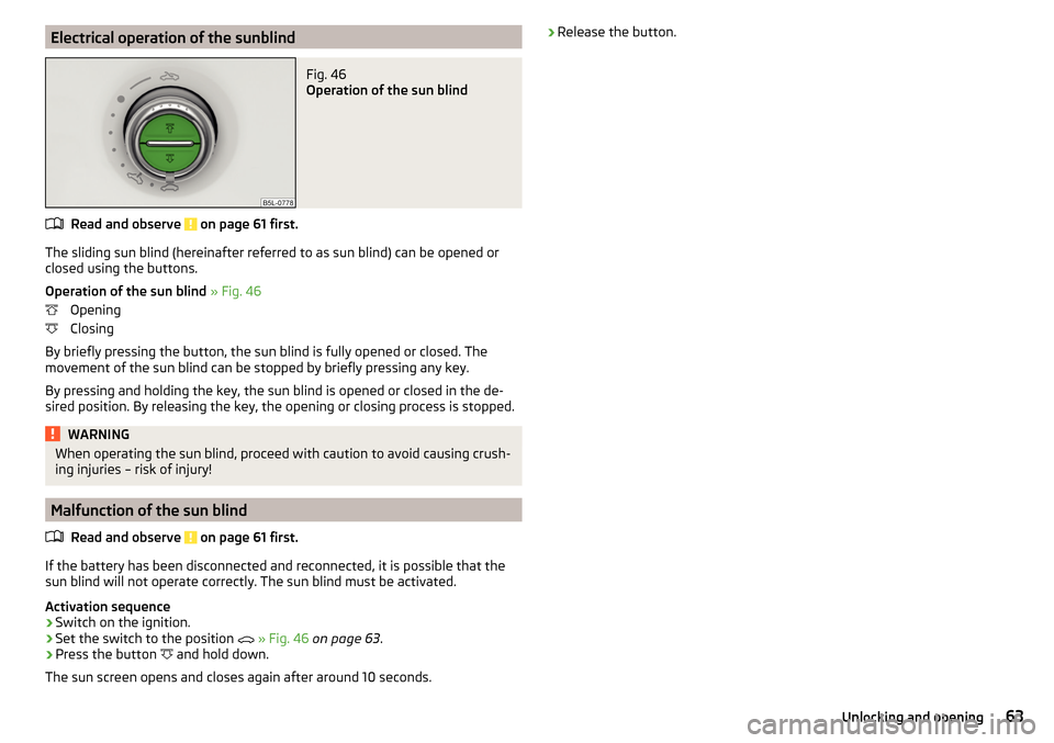
Electrical operation of the sunblindFig. 46
Operation of the sun blind
Read and observe on page 61 first.
The sliding sun blind (hereinafter referred to as sun blind) can be opened orclosed using the buttons.
Operation of the sun blind » Fig. 46
Opening
Closing
By briefly pressing the button, the sun blind is fully opened or closed. The
movement of the sun blind can be stopped by briefly pressing any key.
By pressing and holding the key, the sun blind is opened or closed in the de-
sired position. By releasing the key, the opening or closing process is stopped.
WARNINGWhen operating the sun blind, proceed with caution to avoid causing crush- ing injuries – risk of injury!
Malfunction of the sun blind
Read and observe
on page 61 first.
If the battery has been disconnected and reconnected, it is possible that thesun blind will not operate correctly. The sun blind must be activated.
Activation sequence
›
Switch on the ignition.
›
Set the switch to the position
» Fig. 46 on page 63 .
›
Press the button
and hold down.
The sun screen opens and closes again after around 10 seconds.
› Release the button.63Unlocking and opening
Page 72 of 232
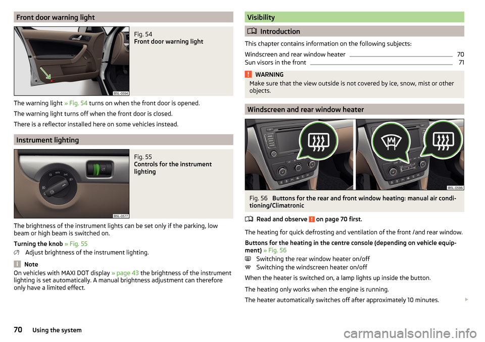
Front door warning lightFig. 54
Front door warning light
The warning light » Fig. 54 turns on when the front door is opened.
The warning light turns off when the front door is closed.
There is a reflector installed here on some vehicles instead.
Instrument lighting
Fig. 55
Controls for the instrument
lighting
The brightness of the instrument lights can be set only if the parking, low
beam or high beam is switched on.
Turning the knob » Fig. 55
Adjust brightness of the instrument lighting.
Note
On vehicles with MAXI DOT display » page 43 the brightness of the instrument
lighting is set automatically. A manual brightness adjustment can therefore
only have a limited effect.Visibility
Introduction
This chapter contains information on the following subjects:
Windscreen and rear window heater
70
Sun visors in the front
71WARNINGMake sure that the view outside is not covered by ice, snow, mist or other
objects.
Windscreen and rear window heater
Fig. 56
Buttons for the rear and front window heating: manual air condi-
tioning/Climatronic
Read and observe
on page 70 first.
The heating for quick defrosting and ventilation of the front /and rear window.Buttons for the heating in the centre console (depending on vehicle equip-
ment) » Fig. 56
Switching the rear window heater on/off Switching the windscreen heater on/off
When the heater is switched on, a lamp lights up inside the button.
The heating only works when the engine is running.
The heater automatically switches off after approximately 10 minutes.
70Using the system
Page 78 of 232
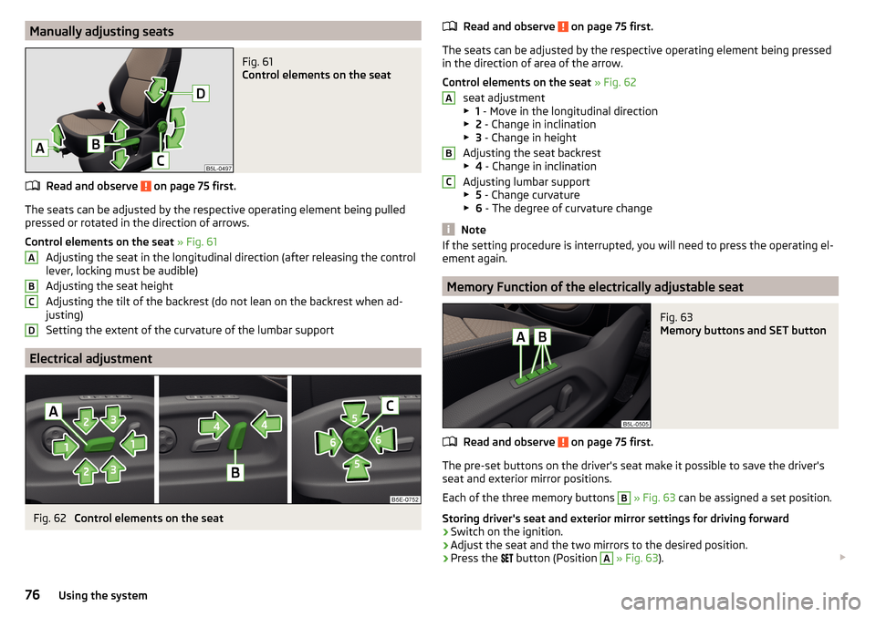
Manually adjusting seatsFig. 61
Control elements on the seat
Read and observe on page 75 first.
The seats can be adjusted by the respective operating element being pulledpressed or rotated in the direction of arrows.
Control elements on the seat » Fig. 61
Adjusting the seat in the longitudinal direction (after releasing the control
lever, locking must be audible)
Adjusting the seat height
Adjusting the tilt of the backrest (do not lean on the backrest when ad-
justing)
Setting the extent of the curvature of the lumbar support
Electrical adjustment
Fig. 62
Control elements on the seat
ABCDRead and observe on page 75 first.
The seats can be adjusted by the respective operating element being pressed in the direction of area of the arrow.
Control elements on the seat » Fig. 62
seat adjustment
▶ 1 - Move in the longitudinal direction
▶ 2 - Change in inclination
▶ 3 - Change in height
Adjusting the seat backrest
▶ 4 - Change in inclination
Adjusting lumbar support
▶ 5 - Change curvature
▶ 6 - The degree of curvature change
Note
If the setting procedure is interrupted, you will need to press the operating el-
ement again.
Memory Function of the electrically adjustable seat
Fig. 63
Memory buttons and SET button
Read and observe on page 75 first.
The pre-set buttons on the driver's seat make it possible to save the driver's seat and exterior mirror positions.
Each of the three memory buttons
B
» Fig. 63 can be assigned a set position.
Storing driver's seat and exterior mirror settings for driving forward
›
Switch on the ignition.
›
Adjust the seat and the two mirrors to the desired position.
›
Press the
button (Position
A
» Fig. 63 ).
ABC76Using the system