steering SMART FORTWO COUPE ELECTRIC DRIVE 2015 Owner's Manual
[x] Cancel search | Manufacturer: SMART, Model Year: 2015, Model line: FORTWO COUPE ELECTRIC DRIVE, Model: SMART FORTWO COUPE ELECTRIC DRIVE 2015Pages: 222, PDF Size: 5.02 MB
Page 133 of 222
It monitors the tire inflation pressure in
all four tires. A warning is issued to alert
you to a decrease in pressure in one or more of the tires.
The Tire Pressure Monitoring System
(TPMS) is equipped with a combination low
tire pressure/TPMS malfunction telltale in the instrument cluster. Depending on how
the telltale illuminates, it indicates a low
tire pressure condition or a malfunction in
the TPMS system itself:
R If the telltale illuminates continuously,
one or more of your tires is significantly
underinflated. There is no malfunction
in the TPMS.
R If the telltale flashes for 60 seconds and
then stays illuminated, the TPMS system
itself is not operating properly.
The TPMS only functions on wheels that are
equipped with the proper electronic sen-
sors. G
WARNING
The TPMS does not indicate a warning for
wrongly selected inflation pressures.
Always adjust tire inflation pressure
according to the Tire and Loading Infor-
mation placard on the driver’s door B‑pil- lar.
The TPMS is not able to issue a warning due to a sudden dramatic loss of pressure (e.g.
tire blowout caused by a foreign object). In
this case bring the vehicle to a halt by
carefully applying the brakes and avoiding abrupt steering maneuvers. G
WARNING
Each tire should be checked monthly when
cold and inflated to the inflation pressure recommended by the vehicle manufacturer
on the Tire and Loading Information plac-
ard. If your vehicle has tires of a differentsize than the size indicated on the Tire and
Loading Information placard, you should
determine the proper tire inflation pres-
sure for those tires. As an added safety feature, your vehicle has
been equipped with a tire pressure moni-
toring system (TPMS) that illuminates a low
tire pressure telltale when one or more of
your tires is significantly underinflated.
Accordingly, when the low tire pressure
telltale illuminates, you should stop and
check your tires as soon as possible, and
inflate them to the proper pressure. Driv-
ing on a significantly underinflated tire
causes the tire to overheat and can lead to
tire failure.
Underinflation also increases energy con-
sumption, reduces tire tread life, and may
affect the vehicle’s handling and stopping
ability. Please note that the TPMS is not a
substitute for proper tire maintenance,
and it is the driver’s responsibility to
maintain correct tire pressure, even if
underinflation has not reached the level to trigger illumination of the TPMS low tire
pressure telltale.
Your vehicle has also been equipped with a TPMS malfunction indicator to indicate
when the system is not operating properly.
The TPMS malfunction indicator is com-
bined with the low tire pressure telltale.
When the system detects a malfunction, the
telltale will flash for approximately
1 minute and then remain continuously
illuminated.
This sequence will continue upon subse-
quent vehicle start-ups as long as the mal-
function exists. When the malfunction
indicator is illuminated, the system may
not be able to detect or signal low tire
pressure as intended.
TPMS malfunctions may occur for a variety
of reasons, including the installation of
incompatible replacement or alternate
tires or wheels on the vehicle that prevent
the TPMS from functioning properly. Always
check the TPMS malfunction telltale after
replacing one or more tires or wheels on
your vehicle to ensure that the replacement Tires and wheels
131>> Operation.
Z
Page 136 of 222
Tire and Loading Information
G
WARNING
Do not overload the tires by exceeding the
specified load limit as indicated on the
Tire and Loading Information placard on
the driver’s door B‑pillar. Overloading the tires can overheat them, possibly causing a
blowout. Overloading the tires can also
result in handling or steering problems, or brake failure.
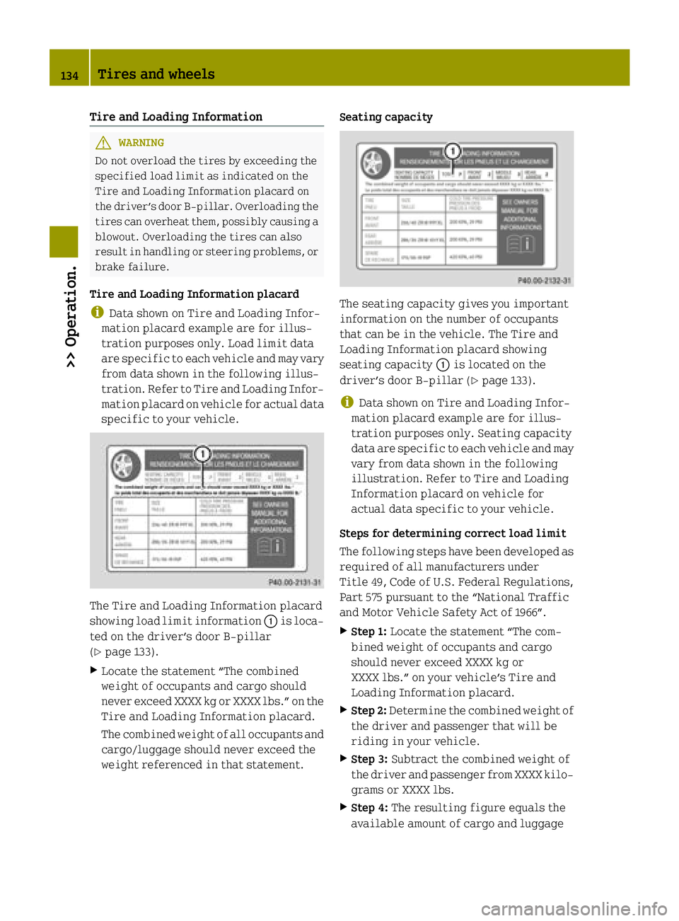
Tire and Loading Information placard
i Data shown on Tire and Loading Infor-
mation placard example are for illus-
tration purposes only. Load limit data
are specific to each vehicle and may vary
from data shown in the following illus-
tration. Refer to Tire and Loading Infor-
mation placard on vehicle for actual data specific to your vehicle. The Tire and Loading Information placard
showing load limit information :is loca-
ted on the driver’s door B‑pillar
(Y page 133).
X Locate the statement “The combined
weight of occupants and cargo should
never exceed XXXX kg or XXXX lbs.” on the
Tire and Loading Information placard.
The combined weight of all occupants and
cargo/luggage should never exceed the
weight referenced in that statement. Seating capacity
The seating capacity gives you important
information on the number of occupants
that can be in the vehicle. The Tire and
Loading Information placard showing
seating capacity :is located on the
driver’s door B‑pillar (Y page 133).
i Data shown on Tire and Loading Infor-
mation placard example are for illus-
tration purposes only. Seating capacity
data are specific to each vehicle and may
vary from data shown in the following
illustration. Refer to Tire and Loading
Information placard on vehicle for
actual data specific to your vehicle.
Steps for determining correct load limit
The following steps have been developed as
required of all manufacturers under
Title 49, Code of U.S. Federal Regulations, Part 575 pursuant to the “National Traffic
and Motor Vehicle Safety Act of 1966”.
X Step 1: Locate the statement “The com-
bined weight of occupants and cargo
should never exceed XXXX kg or
XXXX lbs.” on your vehicle’s Tire and
Loading Information placard.
X Step 2: Determine the combined weight of
the driver and passenger that will be
riding in your vehicle.
X Step 3: Subtract the combined weight of
the driver and passenger from XXXX kilo- grams or XXXX lbs.
X Step 4: The resulting figure equals the
available amount of cargo and luggage 134
Tires and wheels>> Operation.
Page 138 of 222
Examples for steps 1 to 3
Example 1 Example 2
Step 1 Combined weight limit of occu-
pants and cargo from Tire and Load-
ing Information placard 540 lbs 540 lbs
Step 2 Number of occupants (driver and
passenger)
2 1
Occupants weight
Occupant 1: 150 lbs
Occupant 2: 180 lbs Occupant 1: 150 lbs
Combined weight of all occupants
330 lbs 150 lbs
Step 3 Available cargo weight (total load
limit from Tire and Loading Infor-
mation placard minus combined
weight of all occupants) 540 lbs - 330 lbs =
210 lbs 540 lbs - 150 lbs =
390 lbs
Certification label
Even after careful determination of the
combined weight of all occupants and cargo
as to not exceed the permissible load
limit, you must make sure your vehicle
never exceeds the Gross Vehicle Weight
Rating (GVWR) and the Gross Axle Weight
Rating (GAWR) for either the front or rear
axle. You can obtain the GVWR and GAWR
from the certification label. The certifi-
cation label can be found on the driver’s
door B‑pillar, see “Technical data”
(Y page 214).
Gross Vehicle Weight Rating (GVWR) means: The total weight of the vehicle, all occu-
pants, and all cargo must never exceed the
GVWR.
Gross Axle Weight Rating (GAWR) means:
The total allowable weight that can be car-
ried by a single axle (front or rear).
To assure that your vehicle does not exceed the maximum permissible weight limits
(GVWR and GAWR for front and rear axle),
have the loaded vehicle (including driver,
passenger, and all cargo) weighed on a
suitable commercial scale. Maximum tire load
G
WARNING
Do not overload the tires by exceeding the
specified load limit as indicated on the
Tire and Loading Information placard on
the driver’s door B‑pillar. Overloading the tires can overheat them, possibly causing a
blowout. Overloading the tires can also
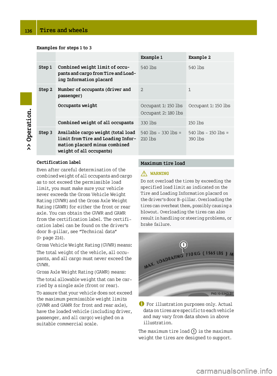
result in handling or steering problems, or brake failure. i
For illustration purposes only. Actual
data on tires are specific to each vehicle and may vary from data shown in above
illustration.
The maximum tire load :is the maximum
weight the tires are designed to support. 136
Tires and wheels>> Operation.
Page 143 of 222
Always replace rims and tires with the same
designation, manufacturer and type as
shown on the original part. G
WARNING
Do not overload the tires by exceeding the
specified load limit as indicated on the
Tire and Loading Information placard on
the driver’s door B‑pillar. Overloading the tires can overheat them, possibly causing a
blowout. Overloading the tires can also
result in handling or steering problems, or brake failure.
Tire load rating Ais a numerical code
associated with the maximum load a tire
can support.
For example, a load rating of 91 corre-
sponds to a maximum load of 1356 lbs
(615 kg) the tire is designed to support.
See also “Maximum tire load” (Y page 136)
where the maximum load associated with
the load index is indicated in kilograms
and lbs.
For additional information on tire load
rating, see “Load identification”
(Y page 142).
Tire speed rating G
WARNING
Even when permitted by law, never operate a
vehicle at speeds greater than the maximum speed rating of the tires.
Exceeding the maximum speed for which
tires are rated can lead to sudden tire fail-
ure, causing loss of vehicle control and
possibly resulting in an accident and/or
personal injury and possible death, for you and for others.
Regardless of the tire speed rating, local
speed limits should be obeyed. Use prudent driving speeds appropriate to prevailing
conditions.
Tire speed rating Bindicates the
approved maximum speed for the tire. Summer tires Index Speed rating
Q up to 100 mph (160 km/h)
R up to 106 mph (170 km/h)
S up to 112 mph (180 km/h)
T up to 118 mph (190 km/h)
H up to 130 mph (210 km/h)
V up to 149 mph (240 km/h)
W up to 168 mph (270 km/h)
Y up to 186 mph (300 km/h)
ZR...Y above 186 mph (300 km/h)
ZR...(Y) above 186 mph (300 km/h)
ZR above 149 mph (240 km/h)
R
At the tire manufacturer’s option, any
tire with a speed capability above
149 mph (240 km/h) can include a “ZR” in
the size designation (for example:
245/40 ZR18). To determine the maximum
speed capability of the tire, the service description for the tire must be referred to.
The service description is comprised of
tire load rating Aand tire speed rating
B.
If your tire includes “ZR” in the size
designation and no service description
is given, the tire manufacturer must be
consulted for the maximum speed capa-
bility.
If a service description is given, the
speed capability is limited by the speed
symbol in the service description.
Example: 245/40 ZR18 97Y.
In this example, “97Y” is the service
description. The letter “Y” designates
the speed rating and the speed capabil- Tires and wheels
141>> Operation. Z
Page 145 of 222
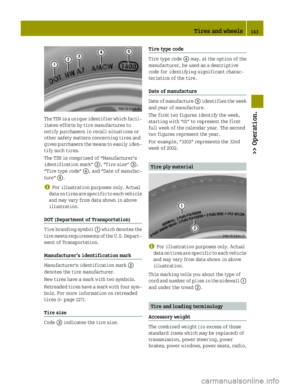
The TIN is a unique identifier which facil-
itates efforts by tire manufactures to
notify purchasers in recall situations or
other safety matters concerning tires and
gives purchasers the means to easily iden- tify such tires.
The TIN is comprised of “Manufacturer’s
identification mark” ;, “Tire size”=,
“Tire type code” ?, and “Date of manufac-
ture” A.
i For illustration purposes only. Actual
data on tires are specific to each vehicle and may vary from data shown in above
illustration.
DOT (Department of Transportation) Tire branding symbol
:which denotes the
tire meets requirements of the U.S. Depart- ment of Transportation.
Manufacturer’s identification mark Manufacturer’s identification mark
;
denotes the tire manufacturer.
New tires have a mark with two symbols.
Retreaded tires have a mark with four sym-
bols. For more information on retreaded
tires (Y page 127).
Tire size Code
=indicates the tire size. Tire type code Tire type code
?may, at the option of the
manufacturer, be used as a descriptive
code for identifying significant charac-
teristics of the tire.
Date of manufacture Date of manufacture
Aidentifies the week
and year of manufacture.
The first two figures identify the week,
starting with “01” to represent the first
full week of the calendar year. The second
two figures represent the year.
For example, “3202” represents the 32nd
week of 2002. Tire ply material
i
For illustration purposes only. Actual
data on tires are specific to each vehicle and may vary from data shown in above
illustration.
This marking tells you about the type of
cord and number of plies in the sidewall :
and under the tread ;. Tire and loading terminology
Accessory weight The combined weight (in excess of those
standard items which may be replaced) of
transmission, power steering, power
brakes, power windows, power seats, radio, Tires and wheels
143>> Operation. Z
Page 149 of 222
For safety reasons, smart recommends
that you only use snow chains that have
been approved by smart.
Information on this is available from any
smart center.
Please refer to the separate operating
instructions for detailed information on mounting the snow chains.
Snow chains should only be driven on
snow-covered roads at speeds not to
exceed 30 mph (50 km/h). Remove chains
as soon as possible when driving on roads
without snow.
Please observe the following guidelines
when using snow chains: R Using snow chains is not permissible
with all wheel/tire combinations
(Y page 216).
R Use snow chains in pairs and on rear
wheels only. Follow the manufacturer’s
mounting instructions.
R Use of snow chains may be prohibited
depending on location. Always check
local and state laws before mounting
snow chains. G
WARNING
When mounting or removing snow chains,
always park your vehicle on level ground,
engage the parking brake, and switch off
the drive system. The vehicle could other-
wise move and injure yourself or other road users. G
WARNING
When mounting and removing snow chains,
ensure that you and your vehicle are at a
safe distance from moving traffic. Not
doing so could endanger other road users or even lead to you being injured by the vehi-cles behind you. G
WARNING
The vehicle’s handling changes when driv-
ing with snow chains on any kind of road
surface. This means that you should always adapt your driving style to suit the current
road and weather conditions.
! If snow chains that do not meet require-
ments are mounted, they may scrape
against the body or axle components when the vehicle is in motion. This could
result in damage to the rim/tire or vehi-
cle. Driving instructions
Drinking and driving
G
WARNING
Do not drink alcohol or take drugs and drive or allow anyone to drive who has been
drinking alcohol or taking drugs. Even a
small amount of alcohol or drugs can affect
your reflexes, perceptions and judgment.
The possibility of a serious or even fatal
accident are greatly increased when you
drink or take drugs and drive. Pedals
G
WARNING
Make sure absolutely no objects are
obstructing the pedals’ range of motion.
Keep the driver’s footwell clear of all
obstacles. If there are any floormats* or
carpets in the footwell, make sure the ped- als still have sufficient clearance.
During sudden acceleration or braking
maneuvers, the objects could get caught
between or beneath the pedals and restrictyour ability to brake or accelerate. This
could lead to accidents and/or injury. Power assistance
G
WARNING
With the drive system inactive, there is no power assistance for the brake and steering
systems. In this case, it is important to Driving instructions
147>> Operation.
* optional Z
Page 153 of 222
imately
1
/ 6 in (4 mm) on all four wheels for
the winter season to ensure normal bal-
anced handling characteristics. On packed
snow, they can reduce your stopping dis-
tance compared to summer tires.
Stopping distance, however, is still con-
siderably greater than when the road is not covered with snow or ice. Exercise appro-
priate caution.
! Avoid spinning of a drive wheel for an
extended period when driving off on
slippery road surfaces. Otherwise, the
drivetrain could be damaged, which is
not covered by the smart Limited War-
ranty. Tire speed rating
Regardless of the tire speed rating, local
speed limits should be obeyed. Use prudent
driving speeds appropriate to prevailing
conditions. G
WARNING
Even when permitted by law, never operate a
vehicle at speeds greater than the maximum speed rating of the tires.
Exceeding the maximum speed for which
tires are rated can lead to sudden tire fail-
ure, causing loss of vehicle control and
possibly resulting in an accident and/or
personal injury and possible death, for you and for others.
Make sure your tires have the required tire speed rating as specified for your vehicle
in the “Technical data section”
(Y page 216), for example when purchasing
new tires.
For information on how to identify the tire
speed rating on a tire’s sidewall, see “Tire size designation, load and speed rating”
(Y page 140).
If you are uncertain about the correct read-
ing of the information given on a tire’s sidewall, any authorized electric drive
smart center will be glad to assist you.
i For information on speed ratings for
winter tires, see “All-season and winter
tires” (Y page 141). Winter driving instructions
The most important rule for slippery or icy roads is to drive sensibly and to avoid
abrupt acceleration, braking and steering
maneuvers.
For information on driving with snow
chains*, see “Snow chains*” (Y page 146).
Road salts and chemicals can adversely
affect braking efficiency. Increased pedal force may become necessary to produce the
normal braking effect.
Depressing the brake pedal periodically
when traveling at length on salt-strewn
roads can bring road-salt-impaired brak- ing efficiency back to normal.
If the vehicle is parked after being driven
on salt-treated roads, the braking effi-
ciency should be tested as soon as possible after driving is resumed. G
WARNING
Make sure not to endanger any other road
users when carrying out these braking
maneuvers. G
WARNING
The outside temperature display is not
designed to serve as an ice-warning device and is therefore unsuitable for that pur-
pose. Indicated temperatures just above
the freezing point do not guarantee that the
road surface is free of ice.
For more information, see “Winter driving”
(Y page 146). Driving instructions
151>> Operation.
* optional Z
Page 169 of 222
Brake
Problem Possible causes/consequences and
M
MSolutions ò
(USA only)
! (Canada only)
The ABS indicator
lamp illuminates
while the drive system is running. There is a malfunction in the ABS system.
X Have the ABS system checked at an authorized electric drive
smart center immediately. ò
(USA only)
! (Canada only)
The ABS indicator
lamp illuminates
together with the
brake warning lamp
$ (USA only) or
J (Canada only)
while the drive system is running. The ABS system fails.
X Stop the vehicle immediately in a safe location.
X Do not continue to drive.
X Switch off the drive system.
X Engage the parking brake when leaving the vehicle.
X Contact Roadside Assistance or an authorized electric drive
smart center. G
WARNING
When the ABS system is malfunctioning, the wheels may lock during hard braking, reducing steering capability and extending the braking distance.
When the ABS is switched off due to a malfunction, the ESP ®
is also switched off. The basic
driving and braking functions are still available.
The risk of your vehicle skidding is then increased in certain situations. You should
therefore always adapt your speed and driving style to the prevailing road and weather
conditions. Problem Possible causes/consequences and
M MSolutions $
(USA only)
J (Canada only)
The brake warning
lamp illuminates
while the drive system is running. You are driving with the parking brake engaged.
X Release the parking brake. The brake circuit fails or the brake fluid level in the brake
fluid reservoir is too low.
X Stop the vehicle immediately in a safe location.
X Do not continue to drive.
X Switch off the drive system.
X Do not add brake fluid as this will not solve the problem.
X Engage the parking brake when leaving the vehicle.
X Contact Roadside Assistance or an authorized electric drive
smart center. What to do if ...
167>> Practical hints. Z
Page 172 of 222
Problem Possible causes/consequences and
M
MSolutions ÷
The ESP ®
warn-
ing lamp
flashes while
driving. The ESP
®
has engaged because of detected traction loss in at
least one tire.
X When driving off, apply as little throttle as possible.
X While driving, ease up on the accelerator pedal.
X Adapt your speed and driving to the prevailing road and
weather conditions. ÷
The ESP ®
warn-
ing lamp illu-
minates con-
tinuously while
the drive sys-
tem is running. The ESP
®
is not operational due to a system failure.
X Have the system checked at an authorized electric drive
smart center. The ESP
®
is not available.
X Have the system checked at an authorized electric drive
smart center. G
WARNING
When the ESP ®
warning lamp is illuminated continuously, the ESP ®
is not available or not
operational due to a system failure.
Adapt your speed and driving to the prevailing road conditions and the non-operating status
of the ESP ®
.
i It may be possible to clear a system failure by restarting the drive system.
X Restart the drive system.
If the warning lamp still does not go out, have the system checked at an authorized
electric drive smart center immediately.
i More information on the ESP ®
can be found in the “Safety” section (Y page 47).Problem Possible causes/consequences and
M MSolutions D
The yellow EPS
warning lamp
illuminates
while the drive
system is run-
ning. The Electronic Power Steering (EPS)* is not available.
X Have the EPS checked at an authorized smart electric drive
center immediately. G
WARNING
When the EPS is not available a higher degree of effort is necessary to steer the vehicle. Have the system checked at an authorized electric drive smart center. 170
What to do if ...>> Practical hints.
* optional
Page 189 of 222
X
Removing: Fold the wiper arm away from
the rear window until you feel it engage.
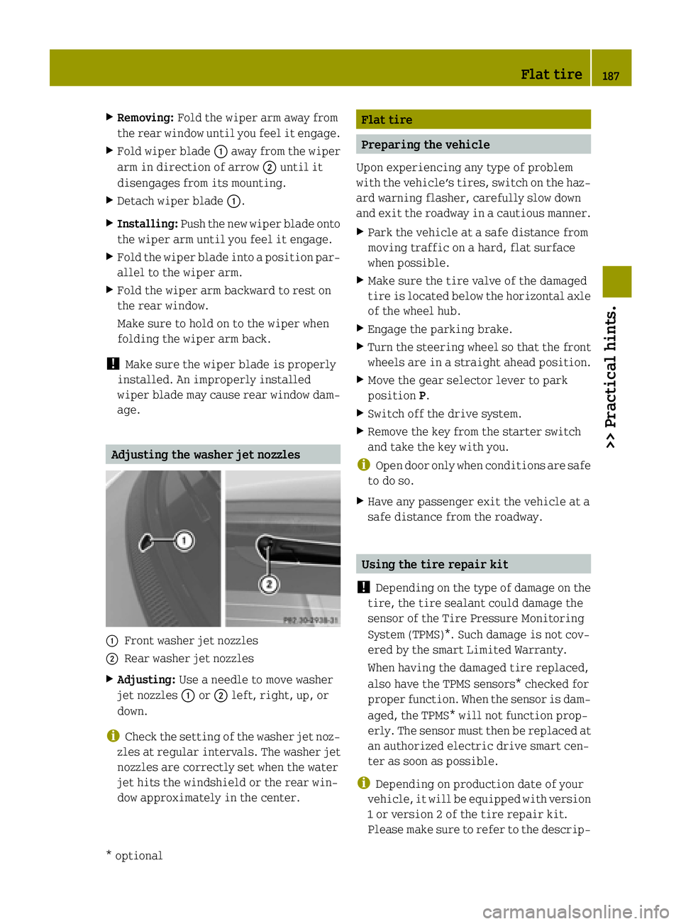
X Fold wiper blade :away from the wiper
arm in direction of arrow ;until it
disengages from its mounting.
X Detach wiper blade :.
X Installing: Push the new wiper blade onto
the wiper arm until you feel it engage.
X Fold the wiper blade into a position par-
allel to the wiper arm.
X Fold the wiper arm backward to rest on
the rear window.
Make sure to hold on to the wiper when
folding the wiper arm back.
! Make sure the wiper blade is properly
installed. An improperly installed
wiper blade may cause rear window dam- age. Adjusting the washer jet nozzles
:
Front washer jet nozzles
; Rear washer jet nozzles
X Adjusting: Use a needle to move washer
jet nozzles :or; left, right, up, or
down.
i Check the setting of the washer jet noz-
zles at regular intervals. The washer jet
nozzles are correctly set when the water
jet hits the windshield or the rear win-
dow approximately in the center. Flat tire
Preparing the vehicle
Upon experiencing any type of problem
with the vehicle’s tires, switch on the haz-
ard warning flasher, carefully slow down
and exit the roadway in a cautious manner.
X Park the vehicle at a safe distance from
moving traffic on a hard, flat surface
when possible.
X Make sure the tire valve of the damaged
tire is located below the horizontal axle
of the wheel hub.
X Engage the parking brake.
X Turn the steering wheel so that the front
wheels are in a straight ahead position.
X Move the gear selector lever to park
position P.
X Switch off the drive system.
X Remove the key from the starter switch
and take the key with you.
i Open door only when conditions are safe
to do so.
X Have any passenger exit the vehicle at a
safe distance from the roadway. Using the tire repair kit
! Depending on the type of damage on the
tire, the tire sealant could damage the
sensor of the Tire Pressure Monitoring
System (TPMS)*. Such damage is not cov-
ered by the smart Limited Warranty.
When having the damaged tire replaced,
also have the TPMS sensors* checked for
proper function. When the sensor is dam-
aged, the TPMS* will not function prop-
erly. The sensor must then be replaced at an authorized electric drive smart cen-
ter as soon as possible.
i Depending on production date of your
vehicle, it will be equipped with version
1 or version 2 of the tire repair kit.
Please make sure to refer to the descrip- Flat tire
187>> Practical hints.
* optional Z