charging SMART FORTWO COUPE ELECTRIC DRIVE 2015 Owners Manual
[x] Cancel search | Manufacturer: SMART, Model Year: 2015, Model line: FORTWO COUPE ELECTRIC DRIVE, Model: SMART FORTWO COUPE ELECTRIC DRIVE 2015Pages: 222, PDF Size: 5.02 MB
Page 6 of 222

1, 2, 3 ...
12-volt battery Charging ................................ 199
Indicator lamp ........................ .171
Notes ..................................... 197
Removing and installing ............ 199 A
ABS (Antilock Brake System) ............. 46
Indicator lamp .........................1 67
Accessory weight .......................... 143
Accidents
Air bags .................................. 33
Acoustic Vehicle Indication* ........... 48
Address change .............................. 15
Air bags ....................................... 33
Children .................................. 33
Front, driver and passenger ......... 36
Front, passenger ....................... 36
Head-thorax ............................. 37
Knee bag .................................. 36
Passenger front air bag off
indicator lamp ..................... 28, 41
Safety guidelines ...................... 35
SRS indicator lamp ...................1 69
Thorax-pelvis ........................... 37
Window curtain ......................... 37
Air conditioning with climate con-
trol
Air distribution ...................... 102
Air recirculation mode .............1 03
Air vents ................................ 101
Air volume .............................. 102
Control panel .......................... 101
Defrosting .............................. 103
Notes ...................................... 99
Rear window defroster ............... 103
Switching on/off ...................... 101
Temperature ............................ 101
Air pressure
see Tire inflation pressure
Air pressure (tires) ...................... 144
Air vents .................................... .101
Alarm system
see Anti-theft systems
Ambient lighting* .......................... 67 Anti-theft systems
.........................48
Anti-theft warning system ........... 49
Electronic immobilizer .............. 48
Interior motion sensor ............... 49
Tow-away alarm .........................49
Anticorrosion/antifreeze ............... 219
Antiglare, Interior rear view mir-
ror .............................................. 61
Antilock Brake System
see ABS
Aquaplaning
see Hydroplaning
Armrest ........................................ 59
Aspect ratio (tires) ....................... 144
Audio system .................................95
Basic ...................................... 96
Navigation/multimedia .............. 96
Automatic headlamp mode ................64
Automatic locking .......................... 53
AUX socket .................................... 96 B
Backrest see Seats
Backup lamp .................................1 81
Bar (air pressure unit) ...................144
Batteries ....................................1 97
Battery
Jump starting .......................... 200
Battery (key)
Replacing the transmitter bat-
tery ....................................... 178
Battery coolant ............................ 125
Bead (tire) .................................. 144
Brake fluid .................................. 127
Checking ................................ 127
Brake lamp ................................... 181
Brake pedal ................................... 78
Brakes ........................................ 148
Parking brake ........................... 77
Warning lamp ........................... 167
Bulbs
Front .................................... .180
Rear ...................................... 181
Replacing .............................. .179 4
Index
Page 7 of 222
 ...... 18
California retail buyers and les-
sees, important notice for ............... 14
Cargo compartment cover blind ........ 104
CD player ......................")
C
CAC (Customer Assistance Center) ...... 18
California retail buyers and les-
sees, important notice for ............... 14
Cargo compartment cover blind ........ 104
CD player ..................................... 95
Center console ............................... 27
Central locking
Automatic ................................ 53
Locking/unlocking from inside .... 53
Certification label ....................... 214
Charge level gauge ......................... 81
Charging
High-voltage battery ................. 112
Charging cable
Connecting .............................. 117
Control element ....................... 116
Storing .................................. 115
Warming up ............................. 114
Child safety
see Children in the vehicle
Children in the vehicle ................... 42
Air bags .................................. 33
Indicator lamp, passenger front
air bag off .......................... 41, 175
Infant and child restraint sys-
tems ....................................... 42
OCS (Occupant Classification
System) ................................... 39
Safety notes ............................. 42
Tether anchorage points ............. 44
Cockpit ........................................ 22
Coin holder ................................. 106
Cold tire inflation pressure ........... 144
Combination switch ........................ 66
Control system
Charge and depart menu .............. 90
Charging mode display ............... 87
Control lever ............................ 83
Introduction ............................ 83
Menus and submenus ................... 89
Messages menu .......................... 93
Multifunction display ................ 83
Odometer menu .......................... 89
Recuperation display ................. 84
Reset menu ............................... 90
Settings menu ........................... 93 Start menu ............................... 90
Time menu ............................... 94
Coolant
Anticorrosion/antifreeze .......... 219
Battery .................................. 125
Capacities ........................ 218, 219
Drive system ........................... 125
Temperature warning lamp ......... 172
Coolant temperature ...................... 152
Copyright ..................................... 20
Cruise control ............................... 97
Curb weight ................................. 144
Customer Assistance Center (CAC) ...... 18 D
Dashboard see Instrument cluster
Daytime running lamp mode .............. 65
Deep water
see Standing water
Defroster
Rear window ............................ 103
Windshield ............................. 103
Department of Transportation
see DOT
Direction of rotation (tires) ........... 137
Door control panel ......................... 28
Door handles ................................. 28
Doors
Locking/unlocking from outside ... 53
Opening from inside .................. 54
DOT (Department of Transporta-
tion) .................................... 142, 144
Drinking and driving .....................147
Drive diagnostics
Indicator lamp ......................... 173
Warning lamp ........................... 173
Driving
Abroad ................................... 153
Coolant temperature ................. 152
Hydroplaning .......................... 150
In winter ................................ 151
Instructions ....................... 76, 147
Safety systems .......................... 46
Through standing water ............. 152
Tips, recuperation ..................... 81
Tips, transmission ..................... 81 Index
5
Page 8 of 222

Driving and parking
Safety notes ............................. 76
Driving safety systems .................... 46
ABS ....................................... .46
ESP ®
....................................... 47
Hydraulic brake assistant ........... 47 E
ECO indicator ............................... 86
Electrical system
Improper work on or modifica-
tions ....................................... 16
Power outlet ............................ 110
Electronic immobilizer .................. 48
Electronic Power Steering
see EPS
Electronic Stability Program
see ESP ®
Emergency Tensioning Device see ETD
Emergency, in case of
Hazard warning flashe r.......... 48, 68
Roadside Assistance ................... 15
Emission control
Information label ..................... 214
System warranties ...................... 13
Engine
Electronics ............................. 212
Starting .................................. 76
Turning off .............................. 79
EPS (Electronic Power Steering)
Warning lamp .......................... 170
ESP ®
(Electronic Stability Program) ... 47
Warning lamp .......................... 170
ETD (Emergency Tensioning Device) ... 33
Safety guidelines ...................... 35
Exterior lamp switch ...................... 64
Exterior lighting
Overview ................................ 180
Exterior rear view mirrors .............. 61F
Flat tire ..................................... 187
Fluids
Capacities .............................. 218
Fog lamps ................................ 67, 180 Front air bags
see Air bags
Front compartment ........................ 123
Front lamps
Overview ................................ 180
Fuse chart ................................... 208
Fuses ......................................... 205 G
GAWR (Gross Axle Weight Rating) ...... 144
Global locking/unlocking ................ 53
Glove box .................................... 106
Gross Axle Weight Rating
see GAWR
Gross Vehicle Weight
see GVW
Gross Vehicle Weight Rating
see GVWR
GVW (Gross Vehicle Weight) ............. 144
GVWR (Gross Vehicle Weight Rating) .. 144 H
Halogen headlamps see Headlamps
Hazard warning flasher .................... 68
Head-thorax air bags ...................... 37
Headlamps
Automatic headlamp mode ............ 64
Daytime running lamp mode ......... 65
High-beam flasher ..................... 66
High-beam headlamps ................. 66
Low-beam headlamps .................. 64
Switch ..................................... 64
Heated exterior rear view mirrors ..... 61
Height adjustment
Seats ...................................... 59
High-beam flasher ......................... 66
High-beam headlamps ................ 66, 180
Indicator lamp ......................... 171
High-mounted brake lamp ............... 181
High-voltage battery
Battery care ............................ 113
Charge level gauge ..................... 81
Charging (AC power socket )......... 114
Charging (control system) ........... 92
Charging (private wallbox) ......... 115 6
Index
Page 9 of 222
 ...................................... 117
Charging cable ........................ 115
Charging cable warming ............ 114
Cruise range .......................")
Charging (public charging sta-
tion) ...................................... 117
Charging cable ........................ 115
Charging cable warming ............ 114
Cruise range ........................... 113
Discharged battery ................... 113
Displaying available power ......... 85
ECO indicator ........................... 86
Energy consumption .................. 113
Intelligent charging manage-
ment ...................................... 123
Introduction ............................ 112
Notes ..................................... 198
Outside temperatures ................ 113
Overvoltage protection .............. 114
Problems with the charging
process .................................. 120
READY indicator ........................ 87
Terms of use ............................ 114
Warning label (wheel change) ...... 196
Warning lamp ........................... 171
High-voltage disconnect device ........ 18
Hill-start assist system .................. 81
Hydraulic brake assistant ................ 47
Hydroplaning ............................... 150 I
Identification labels .................... 214
Identification number, vehicle
(VIN) .......................................... 215
Infant and child restraint systems
see Children in the vehicle
Inflation pressure
see Tires, Inflation pressure
Inside door handle ......................... 54
Instrument cluster .....................23, 25
Illumination ............................ 82
Lamps, indicator and warning ..... 166
Instrument panel
see Instrument cluster
Instruments and controls
see Cockpit
Intelligent charging management
High-voltage battery ................ 123
Interior motion sensor .................... 49
Interior rear view mirror ................ 61Interior storage spaces
see Storage compartments
Intermittent wiping
Rear window wiper ..................... 70
Windshield wipers ..................... 69
Internet connection
Via mobile service module ......... 122
Via powerline .......................... 122 J
Jump-starting ............................. 200 K
Key ............................................. 52
Loss of ................................... 176
Replacing the transmitter bat-
tery ....................................... 178
Kilopascal (air pressure unit) ......... 144
Knee bag ...................................... 36 L
Labels ........................................ 214
Emission control information ..... 214
Lamps, exterior
Exterior lamp switch .................. 64
Switching on/off ....................... 64
Lamps, indicator and warning
12-volt-battery ........................ 171
ABS ........................................ 167
Brakes ................................... 167
Coolant temperature ................. 172
Drive diagnostics .................... 173
EPS ........................................ 170
ESP ®
...................................... 170
Fog lamps ................................ 67
High-beam headlamps ................ 171
High-voltage battery ................. 171
Low tire pressure/TPMS mal-
function telltale ...................... 173
Low-beam headlamps ................. 171
Overview (kilometers) ................ 26
Overview (miles) ....................... 24
Passenger front air bag off .... 36, 175
Seat belt telltale ..................... 168
SRS ........................................ 169
Turn signals ............................ 172 Index
7
Page 17 of 222

charge the high‑voltage battery when no
public charging station is available.
R The operating range of your vehicle is
limited due to the availability of public
charging stations.
R Public charging stations may not be
available at all in some areas.
In light of the foregoing, proper care must
be exercised in the planning of a long dis-
tance trip with the vehicle. smart is not
responsible for the availability of public
charging stations. Roadside Assistance
The smartmove Assistance (Canada) and
smart 1 service (USA) Program provides
factory trained technical help in the event
of a breakdown. Calls to the toll-free Road- side Assistance number
1-800-762-7887 (in the USA)
1-877-627-8004 (in Canada)
will be answered by smart Customer Assis-
tance Representatives 24 hours a day,
365 days a year.
Roadside Assistance will be provided in
accordance with standard program guide-
lines which include providing service to
the vehicle up to a reasonable distance
from a paved roadway. We will make every
effort to assist in a breakdown situation,
however, the accessibility of your vehicle
will be determined by our authorized elec- tric drive smart center technician or the
tow service provider on a case-by-case
basis and may be a factor in our ability to
respond.
Additional charges may be applicable for a breakdown location determined not to be a
reasonably accessible roadside location
as determined by our authorized techni-
cian and tow service provider.
For additional information refer to the
smart Roadside Assistance Program bro-
chure (USA) or the Warranty Booklet (Can-
ada) in your vehicle literature portfolio. Change of address or ownership
In the USA: If you change your address, be
sure to send in the “Information Change
Card” found in the Warranty Information
Booklet.
In Canada: If you change your address, be
sure to send in the “Change of Address
Notice” found in the Warranty Booklet, or
simply call the Customer Service at
1-800-387-0100.
Maintaining your current address infor-
mation with smart will enable us to contact
you should important new information
about the vehicle, such as recalls, become
available.
If you sell your smart, please leave all lit- erature with the vehicle to make it avail-
able to the next operator.
In the USA: If you bought this vehicle used, be sure to send in the “Information ChangeCard” found in the Warranty Information
Booklet.
In Canada: If you bought this vehicle used,
be sure to send in the “Notice of Pre‑Owned Vehicle Purchase” found in the Warranty
Booklet, or call the Customer Service at
1-800-387-0100. Operating your vehicle outside the USA
or Canada
If you plan to operate your vehicle in for-
eign countries, please be aware that:
R Service facilities or replacement parts
may not be readily available.
R The AC power sockets in some countries,
especially overseas, require different
plugs on the charging cable.
R Charging stations may not be available. >> Introduction.
15
Page 19 of 222

partner which is qualified for smart elec-
tric drive.
Particular care should be taken involving
all areas which are in the vicinity of high
voltage parts, e.g. parts in the engine com-
partment. Orange-colored cables and their respective sockets carry high voltage and
must not be damaged.
Serious injury or death can result if you:
R remove the covers of components which
are labeled with a warning sticker.
R handle components of the high-voltage
vehicle electrical system.
R open the housing.
R disconnect plug connectors.
R come into contact with components or
orange-colored cables of the high-volt-
age vehicle electrical system following
an accident.
R come into contact with orange-colored
cables or their damaged plug connectors.
R come into contact with damaged compo-
nents of the high-voltage vehicle elec-
trical system.
Have the damaged orange-colored cables or their damaged plug connectors replaced
immediately at an authorized electric
drive smart center. The service partner
must have the required knowledge and tools
to carry out the necessary work. For safety
reasons, smart recommends using a smart
center which is qualified for smart elec-
tric drive. Particularly for safety-rele-
vant work and work on safety-relevant vehi- cle systems, servicing by an authorized
electric drive smart center is essential.
Do not remove the high-voltage battery of
the high-voltage vehicle electrical sys-
tem. Have the required work carried out by
an authorized electric drive smart center.
smart recommends that you use an author-
ized electric drive smart center. G
WARNING
The high‑voltage battery of the drive sys-
tem is located under the vehicle’s under-
body. When the pressure inside the
high‑voltage battery exceeds a certain
value, for example in case of a vehicle fire, inflammable gas will escape via a duct. Theinflammable gas escapes to an area under
the vehicle. This prevents the high‑voltage
battery from exploding.
Stay away from this area of the vehicle.
When you carry out common works like
replacing bulbs or checking coolant level,
make sure that
R the ignition is switched off
R the charging cable for the high-voltage
battery is disconnected. Automatic switch-off of the high-volt-
age system
The high-voltage system will be automati- cally switched off, in the event:
R of an accident in which the restraint
systems are triggered
R of a short circuit in the high-voltage
system is detected
R that an electric connection in the high-
voltage system has been disconnected
This helps to avoid that you get in contact
with high-voltage. High-voltage battery
G
WARNING
The high‑voltage battery of the drive sys-
tem is located under the vehicle’s under-
body. When the pressure inside the
high‑voltage battery exceeds a certain
value, for example in case of a vehicle fire, inflammable gas will escape via a duct. Theinflammable gas escapes to an area under >> Introduction.
17 Z
Page 84 of 222

Charge level gauge
!
Do not hang any objects on the charge
level gauge.
This could cause the charge level gauge
to be torn from its mountings and be dam-
aged.
The charge level gauge :displays charge
status of the high-voltage battery as a per-
centage.
When the High-voltage Battery at High-voltage Battery at
Reserve Level
Reserve Level message appears in the
multifunction display while the drive sys- tem is in operation, the high-voltage bat-
tery has reached the reserve level.
i If the charge level of the high-voltage
battery has dropped below 20 %, recharge it at:
R an AC power socket (Y page 114)
R a private wall box (Y page 115)
R a public charging station
(Y page 117)
Power gauge G
WARNING
The operating condition of the high-volt-
age battery (e.g. not yet at normal operat-
ing temperature or fully charged) influen- ces the braking effect of the electric
motor.
In overrun or braking mode, the motor's
braking effect may therefore be reduced or
may not be present at all.
As a result of the reduced engine braking
effect, you may cause an accident and
injure yourself or others.
Compensate for the reduced engine braking effect by pressing the brake pedal accord-
ingly, as required.
! Do not hang any objects on the power
gauge.
This could cause the power gauge to be
torn from its mountings and be damaged. Power gauge
;contains two segments:
R Section right of 0
Power gauge ;indicates the current
power that the drive system delivers to
the rear wheels. 100 % correspond to 55 kW peak power.
R Section left of 0
When you release the accelerator pedal
or when you depress the brake pedal, the
electric motor operates as a generator.
Electric current is produced and stored
in the high-voltage battery. As long as
the high-voltage battery is being
charged, the electric motor simulates an
engine brake.
When the pointer of power gauge ;is in
the "OFF“ position, the vehicle is not ready to drive, because:
R the drive system has not been started
R the gear selector lever has not been
moved to position Nor Pwhen starting
the drive system
R the charging cable is connected to the
vehicle
R there is not enough power from the high-
voltage battery
R a problem occured in the high-voltage
system
After the drive system has been started, the pointer of power gauge ;moves to posi-
tion 0.READY
READY appears in the multifunction
display (Y page 87). The vehicle is ready
to drive. Adjusting instrument cluster illumi-
nation
You can adjust the illumination of R the switches and dials in the instrument
cluster
R the radio
R the climate control panel
R the charge level and power gauges
Five illumination levels are available. 82
Instrument cluster>> Controls.
Page 88 of 222

R
Three segments: maximum power is
available.
R Two segments: Less than 66 % amount of
power is available.
R One segment: Less than 33 % amount of
power is available.
Under normal operating conditions the
indicator for the maximum power is at the
maximum range :.
The available amount of power can vary
from the the maximum range due to:
R very high or low outside temperatures
R very high power demand over a long time
period
R very low charge level of the high-voltage
battery
By charging the high-voltage battery, the
reduced availability of power can be
improved (Y page 114). ECO indicator
ECO indicator
:helps you to optimize
your driving style. The energy consumption of your vehicle can be reduced and the
cruising range can be increased.
The calculated ECO value in percent indi-
cates if and how your driving style differs
from an ideal driving style (100 %).
It is calculated from the dynamic factors
R acceleration
R braking behavior
R constant driving Feedback is provided by:
R
your driving style when accelerating and
coasting
- If you accelerate evenly and moder-
ately, the ECO value increases. If you
accelerate hard, the ECO value decrea-
ses.
- Anticipatory, constant driving and
coasting without sudden braking
increases the ECO value.
R the uniformity of your driving style
- If you accelerate moderately, take your
foot off the accelerator pedal early
and avoid frequent braking, your driv- ing style is constant and uniform.
Thus, the ECO value increases.
The ECO indicator summarizes the driving
characteristics from the start of the jour- ney to its completion. For this reason, it
changes dynamically at the beginning of
the journey.
After a prolonged standstill of the vehicle, ECO indicator display :always starts at a
value of 50 %.
Re setting the YSTARTSTART menu (Y page 90),
sets the value of the ECO indicator back to
50 %.
The ECO-value is displayed:
R while driving
R if the key is in starter switch position 2. In place of the ECO display, battery charge
level :and charging time ;appear , if:
R the high‑voltage battery is being
charged
R the key is in starter switch position 1.86
Control system>> Controls.
Page 89 of 222

READY indicator
READY
READY
appears for two seconds in the mul-
tifunction display, if:
R the key is turned to starter switch posi-
tion 2
R there is no malfunction in the drive sys-
tem
The vehicle is ready to drive. Charging mode display
When you switch off the ignition, you see
the display of the charging mode which is
currently set.
The charging mode is not changed after the
ignition has been switched off.
i If the multifunction display has
already gone out, you must turn the key to starter switch position 1. Afterwards,
you can change the setting in the Charge
Charge
and Depart and Depart menu (Ypage 90).
If you do not make a change, the last selec- ted entry is activated. If you have not made
any departure time settings in the last 24
hours, the Instant Charge Instant Charge menu is acti-
vated. Example illustration: Departure time selected
: Preset departure time
; Instant Charge
Instant Charge menu X
To change the setting: press and hold the
control switch on the control lever up or down until the desired mode is selected
in the multifunction display (Y page 83).
Additional information:
R Setting the departure time (Y page 90)
R Starting the charging process immedi-
ately (Y page 92) Outside temperature
G
WARNING
The outside temperature display is not
designed as an ice-warning device and is
therefore unsuitable for that purpose.
Indicated temperatures just above the
freezing point do not guarantee that the
road surface is free of ice. The road may
still be icy, especially in wooded areas or on bridges. Your vehicle could start to skid if you do not adjust your driving style
accordingly.
Therefore, always adjust your driving style
to the prevailing road and weather condi-
tions. Example illustration (U.S. vehicles)
i
Canada vehicles: The outside tempera-
ture display shows °C °Cinstead of °F
°F.
The outside temperature display :
appears in the multifunction display con-
tinuously.
A change of the outside temperature will be displayed with delay. Control system
87>> Controls. Z
Page 93 of 222
This is useful:
R if you wish to cool the interior of the
vehicle before driving
R if you wish to charge the vehicle at a
charging station/wallbox at the most
inexpensive electricity rate
With the "Air conditioning before start"
function, the vehicle interior is cooled
prior to a desired departure time.
Prerequisites:
R The doors and tailgate are closed.
R The charging cable for the high‑voltage
battery is connected to a power source
and inserted into the vehicle's power
socket.
R The high‑voltage battery has a suffi-
cient charge.
The maximum duration of "Air condition-
ing before start" is 30 minutes.
Set the air distribution of your vehicle as
follows so that the "Air conditioning
before start" function has the greatest
effect:
R in summer, to the center and side vents
R in winter, onto the windshield and side
windows
Information on air distribution can be
found on (Y page 102).
The setting of the airflow regulator has no
influence on the "Air conditioning before
start" function.
i If the programmed time is too short, the
high‑voltage battery cannot be com-
pletely charged. After setting the depar- ture time, the maximum charge level
which can be reached is then shown.
i If the high‑voltage battery is not suf-
ficiently charged and the "Air condi-
tioning before start" function is acti-
vated, the high‑voltage battery is
charged first. When a charge level of at
least 20 %has been reached, the "Air con-
ditioning before start" function is acti-
vated. This function then has priority over the charging of the high‑voltage
battery.
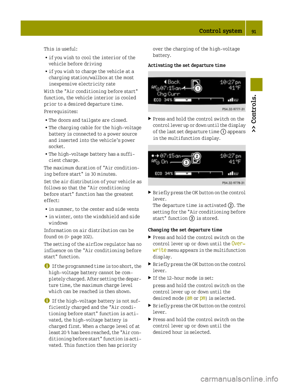
Activating the set departure time X
Press and hold the control switch on the
control lever up or down until the display
of the last set departure time :appears
in the multifunction display. X
Briefly press the OK button on the control
lever.
The departure time is activated ;. The
setting for the "Air conditioning before
start" function =is stored.
Changing the set departure time X Press and hold the control switch on the
control lever up or down until the Over‐
Over‐
write write menu appears in the multifunction
display.
X Briefly press the OK button on the control
lever.
X If the 12-hour mode is set:
press and hold the control switch on the
control lever up or down until the
desired mode (am amorpm pm) is selected.
X Briefly press the OK button on the control
lever.
X Press and hold the control switch on the
control lever up or down until the
desired hour is selected. Control system
91>> Controls. Z