turn signal SSANGYONG KORANDO 1997 Service Owner's Manual
[x] Cancel search | Manufacturer: SSANGYONG, Model Year: 1997, Model line: KORANDO, Model: SSANGYONG KORANDO 1997Pages: 2053, PDF Size: 88.33 MB
Page 502 of 2053
1F2 -- 84 M161 ENGINE CONTROLS
D AEW OO M Y_2000
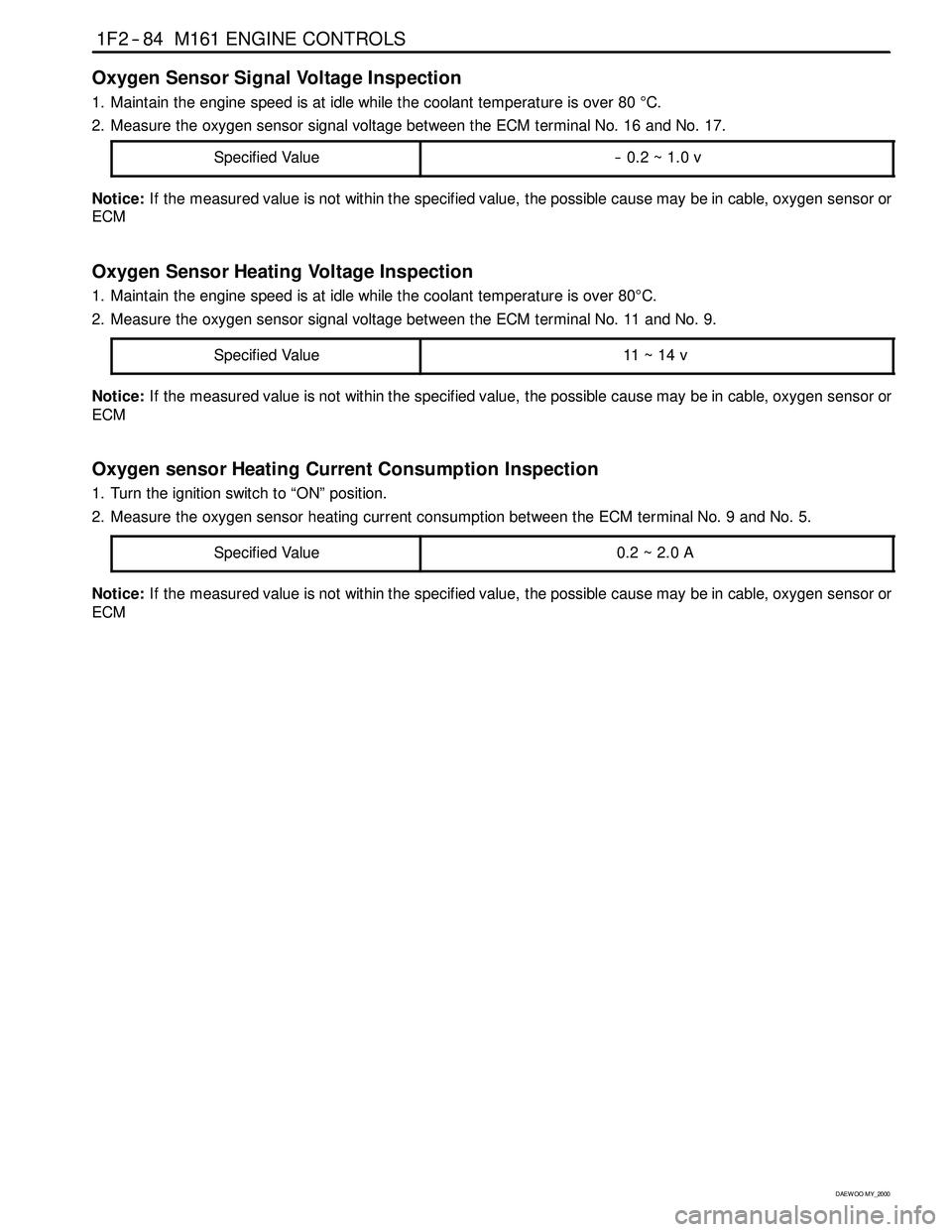
Oxygen Sensor Signal Voltage Inspection
1. Maintain the engine speed is at idle while the coolant temperature is over 80°C.
2. Measure the oxygen sensor signal voltage between the ECM terminal No. 16 and No. 17.
Specified Value
-- 0.2 ~ 1.0 v
Notice:If the measured value is not within the specified value, the possible cause may be in cable, oxygen sensor or
ECM
Oxygen Sensor Heating Voltage Inspection
1. Maintain the engine speed is at idle while the coolant temperature is over 80°C.
2. Measure the oxygen sensor signal voltage between the ECM terminal No. 11 and No. 9.
Specified Value
11 ~ 14 v
Notice:If the measured value is not within the specified value, the possible cause may be in cable, oxygen sensor or
ECM
Oxygen sensor Heating Current Consumption Inspection
1. Turn the ignition switch to “ON” position.
2. Measure the oxygen sensor heating current consumption between the ECM terminal No. 9 and No. 5.
Specified Value
0.2~2.0A
Notice:If the measured value is not within the specified value, the possible cause may be in cable, oxygen sensor or
ECM
Page 512 of 2053
1F2 -- 94 M161 ENGINE CONTROLS
D AEW OO M Y_2000
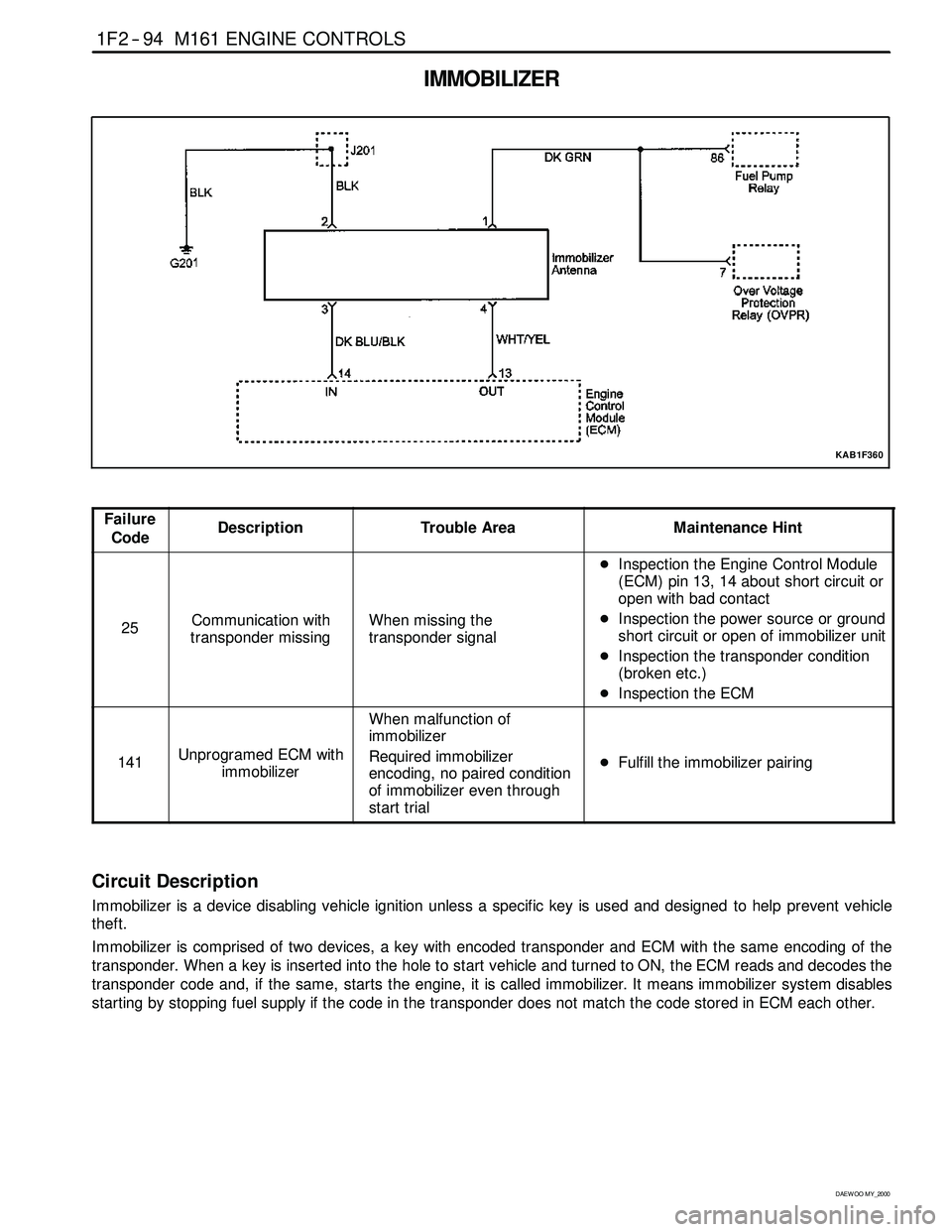
IMMOBILIZER
KAB1F360
Failure
CodeDescriptionTrouble AreaMaintenance Hint
25Communication with
transponder missingWhen missing the
transponder signal
DInspection the Engine Control Module
(ECM) pin 13, 14 about short circuit or
open with bad contact
DInspection the power source or ground
short circuit or open of immobilizer unit
DInspection the transponder condition
(broken etc.)
DInspection the ECM
141Unprogramed ECM with
immobilizer
When malfunction of
immobilizer
Required immobilizer
encoding, no paired condition
of immobilizer even through
start trial
DFulfill the immobilizer pairing
Circuit Description
Immobilizer is a device disabling vehicle ignition unless a specific key is used and designed to help prevent vehicle
theft.
Immobilizer is comprised of two devices, a key with encoded transponder and ECM with the same encoding of the
transponder. When a key is inserted into the hole to start vehicle and turned to ON, the ECM reads and decodes the
transponder code and, if the same, starts the engine, it is called immobilizer. It means immobilizersystem disables
starting by stopping fuel supply if the code in the transponder does not match the code stored in ECM each other.
Page 1100 of 2053

5A-6 AUTOMATIC TRANSMISSION
SSANGYONG MY2002
Solenoids
The TCM controls seven solenoids. Solenoids 1 to 6
(S1 to S6) are mounted in the valve body, while
Solenoid 7 (S7) is mounted in the pump cover.
Solenoid 1 and 2: S1 and S2 are normally open ON/
OFF solenoids that set the selected gear. These
solenoids determine static gear position by
operating the shift valves. Note that S1 and S2
solenoids also send signal pressure to allow or
prohibit rear band engagement.
Solenoid 3 and 4: S3 and S4 are normally open ON/
OFF solenoids that combine to control shift quality
and sequencing. S3 switches the clutch regulator
valve OFF or ON. S4 switches the front band regula-
tor valve OFF or ON. S5 also provides the signal
pressure for the converter clutch regulator valve.
Solenoid 5: S5 is a variable pressure solenoid that
ramps the pressure during gear changes. This sole-
noid provides the signal pressure to the clutch and
band regulator, thereby controlling the shift pres-
sures. S5 also provides the signal pressure for the
converter clutch regulator valve.
Solenoid 6: S6 is a normally open ON/OFF solenoid
that sets the high/low level of line pressure. Solenoid
OFF gives high pressure.
Solenoid 7: S7 is a normally open ON/OFF solenoid
that controls the application of the converter clutch.
Solenoid ON activates the clutch.
Solenoid Logic for Static Gear States
Gear S1 S2
1st ON ON
2nd OFF ON
3 r d OFF OFF
4th ON OFF
Reverse OFF OFF
Neutral OFF OFF
Park OFF OFF
Shift Lever Position Resistance (k
Ω ΩΩ Ω
Ω)
Manual 1 1 ~ 1.4
Manual 221.8 ~ 2.2
Manual 3 3 3 ~ 3.4
Drive4.5 ~ 4.9
Neutral6.8 ~ 7.2
Reverse10.8 ~ 11.2
Park18.6 ~ 19
Kickdown Switch
The Kickdown Switch is used to signal the TCM that
the driver has pressed the acclerator to the floor and
requires a kickdown shift. When this switch is used,
the POWER light comes ON and the POWER shift
pattern is used.
Diagnostic Inputs
The diagnostic control input or K-line is used to initiate
the outputting of diagnostic data from the TCM to a
diagnostic test instrument. This input may also be used
to clear the stored fault history data from the TCM’s
retentive memory. Connection to the diagnostic input
of the TCM is via a connector included in the vehicle’s
wiring harness or computer interface.
Battery Voltage Monitoring Input
The battery voltage monitoring input is connected to
the positive side of the battery. This signal is taken
from the main supply to the TCM.
If the battery voltage at the TCM falls below 11.3 V,
the transmission will adopt a low voltage mode of
operating in which shifts into first gear are inhibited.
All other shifts are allowed but may not occur because
of the reduced voltage. This condition normally occurs
only when the battery is in poor condition.
If the battery voltage is greater than 16.5 V, the trans-
mission will adopt limp home mode and all solenoids
are turned OFF.
When system voltage recovers, the TCM will resume
normal operation after a 30 seconds delay period.
TCM Outputs
The outputs from the TCM are supplied to the compo-
nents described below;
Solenoids
Mode Indicator Light Readings for Resistance / Shift Lever Positions
Page 1102 of 2053

5A-8 AUTOMATIC TRANSMISSION
SSANGYONG MY2002
Solenoid Valve Symbols
(ON/OFF Solenoids)
The solenoid symbol shown adjacent to each solenoid
on the hydraulic system schematics indicates the state
of the oil flow through the solenoid valve with the power
ON or OFF.
Normally Open (NO) Solenoid
POWER ON: Line 500 port is closed. The output port
is open to exhaust at the solenoid valve.
POWER OFF: The exhaust port is closed. The output
port is open to line 500.
Variable Pressure Solenoid Multiplexing System
Friction element shifting pressures are controlled by
the Variable Pressure Solenoid (VPS).
Line pressure is completely independent of shift pres-
sure and is a function of throttle position, gear state
and engine speed.
S5 is a proportional or variable pressure solenoid that
provides the signal pressure to the clutch and band
regulator valves thereby controlling shift pressures.
VPS pressure is multiplexed to the clutch regulator
valve, the band regulator valve and the converter clutch
regulator valve during automatic gearshifts.
A variable pressure solenoid produces a hydraulic
pressure inversely proportional to the current applied.
During a gearshift the TCM applies a progressively
increasing or decreasing (ramped) current to the
solenoid. Current applied will vary between a minimum
oaf 200 mA and a maximum of 1000 mA. Increasing
current decreases output (S5) pressure. Decreasing
current increases output (S5) pressure.
Line 500 pressure, (approximately 440 to 560 kPa), is
the reference pressure for the VPS, and the VPS output
pressure is always below line 500 pressure.
When the VPS is at standby, that is no gearshift is
taking place, the VPS current is set to 200 mA giving
maximum output pressure.
Under steady state conditions the band and clutch
regulator valve solenoids are switched OFF.This applies full Line 500 pressure to the plunger and
because Line 500 pressure is always greater than S5
pressure it squeezes the S5 oil out between the
regulator valve and the plunger. The friction elements
are then fed oil pressure equal to Line 500 multiplied
by the amplification ratio.
When a shift is initiated the required ON/OFF solenoid
is switched ON cutting the supply of Line 500 to the
plunger.
At the same time the VPS pressure is reduced to the
ramp start value and assumes control of the regulator
valve by pushing the plunger away from the valve.
The VPS then carries out the required pressure ramp
and the timed shift is completed by switching OFF the
ON/ OFF solenoid and returning the VPS to the standby
pressure.
This system enables either the band or clutch or both
to be electrically controlled for each gearshift.
Mode Indicator Light
Depending on the application, the mode indicator light
may be used to indicate the mode that has been se-
lected or if an overheat condition exists. The mode
indicator light is usually located on the instrument
cluster.
Communication Systems
CAN
The Controller Area Network (CAN) connects various
control modules by using a twisted pair of wires, to
share common information. This results in a reduction
of sensors and wiring. TCM obtains the actual engine
speed and throttle position, vehicle speed and
accelerator position etc. from ECM via CAN without
any additional sensors.
K-Line
The K-line is typically used for obtaining diagnostic
information from the TCM. A scan tool with a special
interface is connected to the TCM via Data Link
Connector (DLC) and all current faults, stored faults,
runtime parameters are then available. The stored
trouble codes can also be cleared by scan tool.
The K-line can be used for vehicle coding at the
manufacturer’s plant or in the workshop. This allows
for one TCM design to be used over different vehicle
mod-els.
The particular code is sent to the microprocessor via
the K-line and this results in the software selecting the
correct shift and VPS ramp parameters.
Data Link Connector (DLC)
The Data Link Connector (DLC) is a multiple cavity
connector. The DLC provides the means to access the
serial data from the TCM.
The DLC allows the technician to use a scan tool to
monitor the various systems and display the Diagnostic
Trouble Codes (DTCs).
KAA5A070
Page 1107 of 2053

AUTOMATIC TRANSMISSION 5A-13
SSANGYONG MY2002
Reverse Lockout Valve
The reverse lockout valve is a two position valve con-
tained in the upper valve body. This valve uses S1-S2
pressure as a signal pressure and controls the applica-
tion of the rear band (B2).
While the manual valve is in D, 3, 2 or 1 positions,
drive oil is applied to the spring end of the valve,
overriding any signal pressures and holding the valve
in the lockout position. This prevents the application
of B2 in any of the forward driving gears except M1.S1- S2 pressure is exhausted and the valve is held in
the lockout position by the spring. In this position,
engagement of B2 is prohibited.
This feature protects the transmission from abuse by
preventing the undesirable application of B2 at high
speed, and by providing a reverse lockout function.
Note that if the transmission is in failure mode, the
rear band will be applied at all times in P, R and N.
Pump Cover
When the manual valve is in P, R or N positions, drive
oil is exhausted and the reverse lockout valve may be
toggled by S1-S2 pressure.
B2 is applied in P, R, and N if the following conditions
are satisfied;
In P or N, vehicle speed = 3 km/h.
In R, vehicle speed = 10 km/h.
Engine speed = 1600 rpm.
Throttle position = 12 %.
Under these conditions, the TCM switches solenoids
S1 and S2 to OFF. The reverse lockout valve toggles
under the influence of the S1-S2 pressure, to connect
the line pressure to the B2 feed. Oil is fed to both the
inner and outer apply areas of the rear servo piston,
applying B2.
If any of the above conditions are not satisfied, the
TCM switches solenoids S1 and S2 to ON.Primary Regulator Valve
The Primary Regulator Valve (PRV) regulates the trans-
mission line pressure (or pump output pressure). This
valve gives either high or low line pressure depending
on whether S6 is switched OFF or ON. When S6 is
switched ON, S6 pressure is applied to the PRV moving
it against spring pressure and opening the line
pressure circuit to the pump suction port resulting in
reduced line pressure.
Low line pressure is used during light throttle applica-
tions and cruising. Heavy throttle will cause S6 to switch
OFF and thereby cause high line pressure.
This stepped line pressure control has no detrimental
effect on shift feel because all shifting pressures are
controlled by separate band and clutch regulator
valves, and the output of S5.
When reverse gear is selected, both the low and high
line pressure values are boosted to guard against slip-
page. This is achieved by applying reverse oil line
pressure to the PRV to assist the spring load. The
other end of the valve contains ports for line pressure
feedback and S6 pressure.
The PRV also regulates the supply of oil to the
converter via the converter feed port. The cascade
effect of the PRV ensures the first priority of the valve
is to maintain line pressure at very low engine speeds.
When the engine speed increases and the pump
supplies an excess of oil the PRV moves to uncover
the converter feed port thereby pressurizing the
converter. If there is an excess of oil for the
transmission’s needs then the PRV moves further to
allow oil to return to the suction port.
KAA5A170
KAA5A180KAA5A190
Page 1108 of 2053
5A-14 AUTOMATIC TRANSMISSION
SSANGYONG MY2002
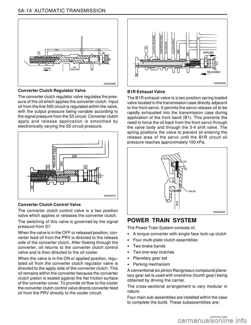
Converter Clutch Regulator Valve
The converter clutch regulator valve regulates the pres-
sure of the oil which applies the converter clutch. Input
oil from the line 500 circuit is regulated within the valve,
with the output pressure being variable according to
the signal pressure from the S5 circuit. Converter clutch
apply and release application is smoothed by
electronically varying the S5 circuit pressure.
Converter Clutch Control Valve
The converter clutch control valve is a two position
valve which applies or releases the converter clutch.
The switching of this valve is governed by the signal
pressure from S7.
When the valve is in the OFF or released position, con-
verter feed oil from the PRV is directed to the release
side of the converter clutch. After flowing through the
converter, oil returns to the converter clutch control
valve and is then directed to the oil cooler.
When the valve is in the ON or applied position, regu-
lated oil from the converter clutch regulator valve is
directed to the apply side of the converter clutch. This
oil remains within the converter because the converter
clutch piston is sealed against the flat friction surface
of the converter cover. To provide oil flow to the cooler
the converter clutch control valve directs converter feed
oil from the PRV directly to the cooler circuit.B1R Exhaust Valve
The B1R exhaust valve is a two position spring loaded
valve located in the transmission case directly adjacent
to the front servo. It permits the servo release oil to be
rapidly exhausted into the transmission case during
application of the front band (B1). This prevents the
need to force the oil back from the front servo through
the valve body and through the 3-4 shift valve. The
spring positions the valve to prevent oil entering the
release area of the servo until the B1R circuit oil
pressure reaches approximately 100 kPa.
POWER TRAIN SYSTEM
The Power Train System consists of;
A torque converter with single face lock-up clutch
Four multi-plate clutch assemblies
Two brake bands
Two one-way clutches
Planetary gear set
Parking mechanism
A conventional six pinion Ravigneaux compound plane-
tary gear set is used with overdrive (fourth gear) being
obtained by driving the carrier.
The cross-sectional arrangement is very modular in
nature.
Four main sub-assemblies are installed within the case
to complete the build. These subassemblies are;
KAA5A220KAA5A200
KAA5A210
KAA5A240
Page 1132 of 2053
5A-38 AUTOMATIC TRANSMISSION
SSANGYONG MY2002
DIAGNOSIS
BASIC KNOWLEDGE REQUIRED
You must be familliar with some basic electronics to
use this section of the Service Manual. They will help
you to follow diagnostic procedures.
Notice: Lack of the basic knowledge of this transmis-
sion when performing diagnostic procedures could re-
sult in incorrect diagnostic performance or damage to
transmission components. Do not, under any circum-
stances, attempt to diagnose a transmission problem
without this basic knowledge.
Notice: If a wire is probed with a sharp instrument
and not properly sealed afterward, the wire will corrode
and an open circuit will result.
Diagnostic test probes are now available that allow
you to probe individual wires without leaving the wire
open to the environment. These probe devices are
inexpensive and easy to install, and they permanently
seal the wire from corrosion.
Special Tools
You should be able to use a Digital Volt Meter (DVM),
a circuit tester, jumper wires or leads and a line
pressure gauge set. The functional check procedure
is designed to verify the correct operation of electronic
components in the transmission. This will eliminate the
unnecessary removal of transmission components.
FUNCTIONAL CHECK
PROCEDURE
Begin with the Functional Check Procedure which pro-
vides a general outline of how to diagnose automatic
transmission. The following functional check procedure
will indicate the proper path of diagnosing the transmis-
sion by describing the basic checks and then referenc-
ing the locations of the specific checks.
Check the fluid level according to the Fluid Level
Service Procedure.
Check the transmission fluid leak.
Check if the transmission fluid is not burnt by smell.
Notice: The specific fluid used in this transmission
turns brown during normal operation. Brown fluid
does not indicate a transmission fault.
Ensure that the transmission is not in Limp Home
Mode (LHM).
Check the battery terminals and the earth connec-
tions for corrosion or looseness.
Check that the cooler flow is not restricted.
Check all electrical plug connections for tightness.
Use on-board diagnostic tool or a scan tool to see
if any transmission trouble codes have been set.
DIAGNOSTIC INFORMATION AND PROCEDURES
Refer to the appropriate “Diagnostic Trouble Code
(DTC)” information and repair the vehicle as
directed. After repairing the vehicle, perform the
road test and verify that the code has not set again.
Perform the Electrical/Garage Shift Tests.
Perform the Road Test Procedure in this section.
Inspect the oil and check for metal or other contami-
nants in the oil pan.
TRANSMISSION FLUID LEVEL
SERVICE PROCEDURE
This procedure is to be used when checking a concern
with the fluid level in a vehicle. A low fluid level will
result in slipping and loss of drive/ reverse or delay on
engagement of drive/ reverse when the vehicle is cold.
The vehicle is first checked for transmission diagnostic
messages on the scan tool. If the oil level is low, it is
possible to register a vehicle speed signal fault.
The vehicle is to be test driven to determine if there is
an abnormal delay when selecting drive or reverse, or
loss of drive. One symptom of low fluid level is a
momentary loss of drive when driving the vehicle around
a corner. Also when the transmission fluid level is low,
a loss of drive may occur when the transmission fluid
temperature is low.
If there is no loss of drive when the vehicle is driven
warm and a vehicle speed signal fault is registered,
then fluid should be added to the transmission.
When adding or changing transmission fluid use only
Castrol TQ 95 automatic transmission fluid. The use of
incorrect fluid will cause the performance and durability
of the transmission to be severely degraded.
Fluid Level Diagnosis procedure
1. If the vehicle is at operating temperature allow the
vehicle to cool down for two hours, but no greater
than four hours. Or if the vehicle is at cool status,
start the engine and allow the engine to idle for
approximately 5 minutes or, if possible, drive the
vehicle for a few kilometers. This will allow the
transmission to be within the correct temperature
range. Transmission fluid level should be checked
at temperature 50 - 60 °C (82 - 140 °F).
Caution: Removal of the fluid filler plug when
the transmission fluid is hot may cause injury if
fluid drains from the filler hole.
2. With the brake pedal pressed, move the gear shift
control lever through the gear ranges, pausing a
few seconds in each range. Return the gear shift
control lever to P (Park). Turn the engine OFF.
3. Park the vehicle on a hoist, inspection pit or similar
raised level surface. The vehicle must be control
level to obtain a correct fluid level measurement.
Page 1134 of 2053
5A-40 AUTOMATIC TRANSMISSION
SSANGYONG MY2002
Dye and Black Light Method
1. Add dye to the transmission through the transmission
fluid filler plug. Follow the manufacturer’s recommen-
dation for the amount of dye to be used.
2. Use the black light to find the fluid leak.
3. Make the necessary repairs.
Repairing the Fluid Leak
Once the leak point is found the source of the leak
must be determined. The following list describes the
potential causes for the leak:
Fasteners are not torqued to specification.
Fastener threads and fastener holes are dirty or
corroded.
Gaskets, seals or sleeves are misaligned, damaged
or worn.
Damaged, warped or scratched seal bore or gasket
surface.
Loose or worn bearing causing excess seal or sleeve
wear.
Case or component porosity.
Fluid level is too high.
Plugged vent or damaged vent tube.
Water or coolant in fluid.
Fluid drain back holes plugged.
ELECTRICAL / GARAGE SHIFT
TEST
This preliminary test should be performed before a hoist
or road test to make sure electronic control inputs are
connected and operating. If the inputs are not checked
before operating the transmission, a simple electrical
condition could be misdiagnosed as a major
transmission condition.
A scan tool provides valuable information and must
be used on the automatic transmission for accurate
diagnosis.
1. Move gear shift control lever to P (Park) and set
the parking brake.
2. Connect scan tool to Data Link Connector (DLC)
terminal.
3. Start engine.
4. Turn the scan tool ON.
5. Verify that the appropriate signals are present.
These signals may include:
ENGINE SPEED
VEHICLE SPEED
THROTTLE POSITION
ACCEL. PEDAL POSITION
TRANSMISSION GEAR STATE
GEAR SHIFT LEVER POSITION
TRANSMISSION FLUID TEMPERATURE
CLOSED THROTTLE POSITION LEARN
OPEN THROTTLE POSITION LEARNT
CLOSED ACCEL. PEDAL POSITION LEARNT
OPEN ACCEL. PEDAL POSITION LEARNT
A/C COMPRESSOR STATUS
KICKDOWN SWITCH STATUS
4WD STATUS
MODE SWITCH
THROTTLE POSITION VOLTAGE
GEAR SHIFT LEVER POSITION VOLTAGE
TRANS. FLUID TEMPERATURE VOLTAGE
A/C SWITCH
KICKDOWN SWITCH VOLTAGE
4WD LAMP LOW VOLTAGE
4WD LAMP HIGH VOLTAGE
MODE SWITCH VOLTAGE
BATTERY VOLTAGE
6. Monitor the A/C COMPRESSOR STATUS signal
while pushing the A/C switch.
The A/C COMPRESSOR STATUS should come
ON when the A/C switch is pressed, and turn
OFF when the A/C switch is repushed.
7. Monitor the GEAR SHIFT LEVER POSITION signal
and move the gear shift control lever through all
the ranges.
Verify that the GEAR SHIFT LEVER POSITION
value matches the gear range indicated on the
instrument panel or console.
Gear selections should be immediate and not
harsh.
8. Move gear shift control lever to neutral and monitor
the THROTTLE POSITION signal while increasing
and decreasing engine speed with the accelerator
pedal.
THROTTLE POSITION should increase with en-
gine speed.
ROAD TEST PROCEDURE
Perform the road test using a scan tool.
This test should be performed when traffic and road
conditions permit.
Observe all traffic regulations.
ELECTRONIC ADJUSTMENTS
Idle Speed Adjustments
Carry out the adjustments to the idle speed as detailed
in the workshop manual.
Vehicle Coding
The vehicle coding is integrated as part of the
diagnostic software. A scan tool has the function to
code the ve-hicle through the K-line.
Page 1135 of 2053
5A-40 AUTOMATIC TRANSMISSION
SSANGYONG MY2002
Dye and Black Light Method
1. Add dye to the transmission through the transmission
fluid filler plug. Follow the manufacturer’s recommen-
dation for the amount of dye to be used.
2. Use the black light to find the fluid leak.
3. Make the necessary repairs.
Repairing the Fluid Leak
Once the leak point is found the source of the leak
must be determined. The following list describes the
potential causes for the leak:
Fasteners are not torqued to specification.
Fastener threads and fastener holes are dirty or
corroded.
Gaskets, seals or sleeves are misaligned, damaged
or worn.
Damaged, warped or scratched seal bore or gasket
surface.
Loose or worn bearing causing excess seal or sleeve
wear.
Case or component porosity.
Fluid level is too high.
Plugged vent or damaged vent tube.
Water or coolant in fluid.
Fluid drain back holes plugged.
ELECTRICAL / GARAGE SHIFT
TEST
This preliminary test should be performed before a hoist
or road test to make sure electronic control inputs are
connected and operating. If the inputs are not checked
before operating the transmission, a simple electrical
condition could be misdiagnosed as a major
transmission condition.
A scan tool provides valuable information and must
be used on the automatic transmission for accurate
diagnosis.
1. Move gear shift control lever to P (Park) and set
the parking brake.
2. Connect scan tool to Data Link Connector (DLC)
terminal.
3. Start engine.
4. Turn the scan tool ON.
5. Verify that the appropriate signals are present.
These signals may include:
ENGINE SPEED
VEHICLE SPEED
THROTTLE POSITION
ACCEL. PEDAL POSITION
TRANSMISSION GEAR STATE
GEAR SHIFT LEVER POSITION
TRANSMISSION FLUID TEMPERATURE
CLOSED THROTTLE POSITION LEARN
OPEN THROTTLE POSITION LEARNT
CLOSED ACCEL. PEDAL POSITION LEARNT
OPEN ACCEL. PEDAL POSITION LEARNT
A/C COMPRESSOR STATUS
KICKDOWN SWITCH STATUS
4WD STATUS
MODE SWITCH
THROTTLE POSITION VOLTAGE
GEAR SHIFT LEVER POSITION VOLTAGE
TRANS. FLUID TEMPERATURE VOLTAGE
A/C SWITCH
KICKDOWN SWITCH VOLTAGE
4WD LAMP LOW VOLTAGE
4WD LAMP HIGH VOLTAGE
MODE SWITCH VOLTAGE
BATTERY VOLTAGE
6. Monitor the A/C COMPRESSOR STATUS signal
while pushing the A/C switch.
The A/C COMPRESSOR STATUS should come
ON when the A/C switch is pressed, and turn
OFF when the A/C switch is repushed.
7. Monitor the GEAR SHIFT LEVER POSITION signal
and move the gear shift control lever through all
the ranges.
Verify that the GEAR SHIFT LEVER POSITION
value matches the gear range indicated on the
instrument panel or console.
Gear selections should be immediate and not
harsh.
8. Move gear shift control lever to neutral and monitor
the THROTTLE POSITION signal while increasing
and decreasing engine speed with the accelerator
pedal.
THROTTLE POSITION should increase with en-
gine speed.
ROAD TEST PROCEDURE
Perform the road test using a scan tool.
This test should be performed when traffic and road
conditions permit.
Observe all traffic regulations.
ELECTRONIC ADJUSTMENTS
Idle Speed Adjustments
Carry out the adjustments to the idle speed as detailed
in the workshop manual.
Vehicle Coding
The vehicle coding is integrated as part of the
diagnostic software. A scan tool has the function to
code the ve-hicle through the K-line.
Page 1152 of 2053

AUTOMATIC TRANSMISSION 5A-57
SSANGYONG MY2002
DTC P0707 Transmission Range Sensor Circuit Low Input
1Perform a Transmission Control Module (TCM)
Diagnostic System Check.
Is the check performed?
1. Turn the ignition ON, with the engine OFF.
2. Install a scan tool.
3. Record and then clear DTCs.
4. Operate the vehicle within the conditions for
setting this DTC as specified in the text.
5. Review the TR Sensor value on the scan tool.
Is the TR Sensor value less than the specified value?
1. Turn the ignition OFF.
2. Disconnect the Transmission Range (TR) sensor
connector.
3. Turn the ignition ON.
Is the TR Sensor value greater than specified value?
Replace the TR sensor.
Is the action complete?
With a test light connected to B+, probe the TR
sensor signal circuit at terminal 1.
Does the test light illuminate?
1. Turn the ignition OFF.
2. Disconnect the Transmission Control Module (TCM)
connector A.
3. Turn the ignition ON.
4. With a test light connected to B+, probe the TR
sensor signal circuit at terminal 1.
Does the test light illuminate?
Repair the short to ground in the TR sensor signal
circuit.
Is a repair complete?
Check for a poor connection at the TR sensor connector
and TCM connector and repair the malfunctioning
terminals as necessary.
Is a repair necessary?
1. Turn the ignition OFF.
2. Replace the TCM.
Is the action complete?
1. Using the scan tool, clear the DTCs.
2. Road test the vehicle within the conditions for
setting this DTC as specified in the text.
Does the scan tool indicate that this diagnostic has
run and passed?
Check if any DTCs are set.
Are there any DTCs displayed or DTC previously
recorded at Step 2 that have not been diagnosed?
StepAction Value(s) Yes No
2
3
- Go to Step 6 Go to Step 8 5
- Go to Step 7 Go to Step 9 6
- Go to Step 10 - 4
7
- Go to Step 10 - 8
- Go to Step 10 - 9
- Go to Step 11 10
11
- Go to Step 2Go to “TCM
Diagnostic
System Check”
4.12 V
Go to Step 4 Go to Step 5
0.87 V Go to Step 3 Go to
“Diagnostic
Aids”
-Go to
applicable
DTC tableSystem OK,
Check
Complete
- Go to Step 10 -