turn signal SSANGYONG KORANDO 1997 Service Workshop Manual
[x] Cancel search | Manufacturer: SSANGYONG, Model Year: 1997, Model line: KORANDO, Model: SSANGYONG KORANDO 1997Pages: 2053, PDF Size: 88.33 MB
Page 1493 of 2053

POWER STEERING AND COLUMN 6E-7
SSANGYONG MY2002
Check the turn signal/dimmer switch and turn signal/
dimmer switch lever for improper installation.
Check the signal/dimmer switch housing for foreign
material.ChecksActionRemove and inspect the turn signal/dimmer switch
and signal/dimmer switch lever. Reinstall the signal/
dimmer switch and signal/dimmer switch lever.
Remove any foreign material.
Turn Signal Will Not Indicate Lane Change
No Turn Signal Lights
Check for an inoperative turn signal flasher.
Check for a faulty turn signal switch.
Check the chassis-to-column connector for an
improper connection.ChecksActionReplace the turn signal flasher.
Replace the turn signal switch.
Reconnect the chassis-to-column connector.
Turn Signal/Dimmer Switch Difficult to Operate
Check for a broken lane change pressure pad or a
broken spring hanger.
Check for improper functioning of the lane change spring.
Check the turn signal switch for improper installation.ChecksActionReplace the lane change pressure pad or the spring
hanger.
Replace the lane change spring.
Replace the turn signal switch.
Turn Indicator Lights On, but Not Flashing
Check for a faulty turn signal switch.
Check the chassis-to-column connector for an im-
proper connection.ChecksActionReplace the turn signal switch.
Reconnect the chassis-to-column connector.
Front or Rear Turn Signal Lights Not Flashing
Turn Signal Lights Flash Very Slowly
Check the chassis-to-column connector for an im-
proper connection.ChecksActionReconnect the chassis-to-column connector.
Check for an inoperative turn signal flasher.
Check for a faulty turn signal switch.
Check the chassis-to-column connector for an im-
proper connection.ChecksActionReplace the turn signal flasher.
Replace the turn signal switch.
Reconnect the chassis-to-column connector.
Page 1495 of 2053

POWER STEERING AND COLUMN 6E-9
SSANGYONG MY2002
KAA6E060
KAA6E040
ON-VEHICLE SERVICE
HEADLAMP/TURN SIGNAL
SWITCH AND LEVER
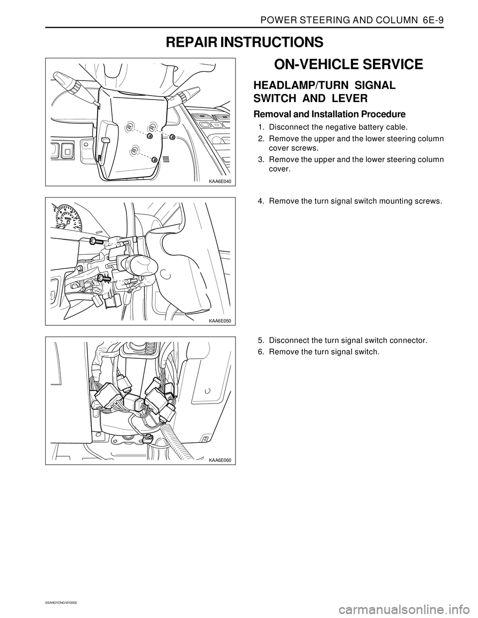
Removal and Installation Procedure
1. Disconnect the negative battery cable.
2. Remove the upper and the lower steering column
cover screws.
3. Remove the upper and the lower steering column
cover.
REPAIR INSTRUCTIONS
KAA6E050
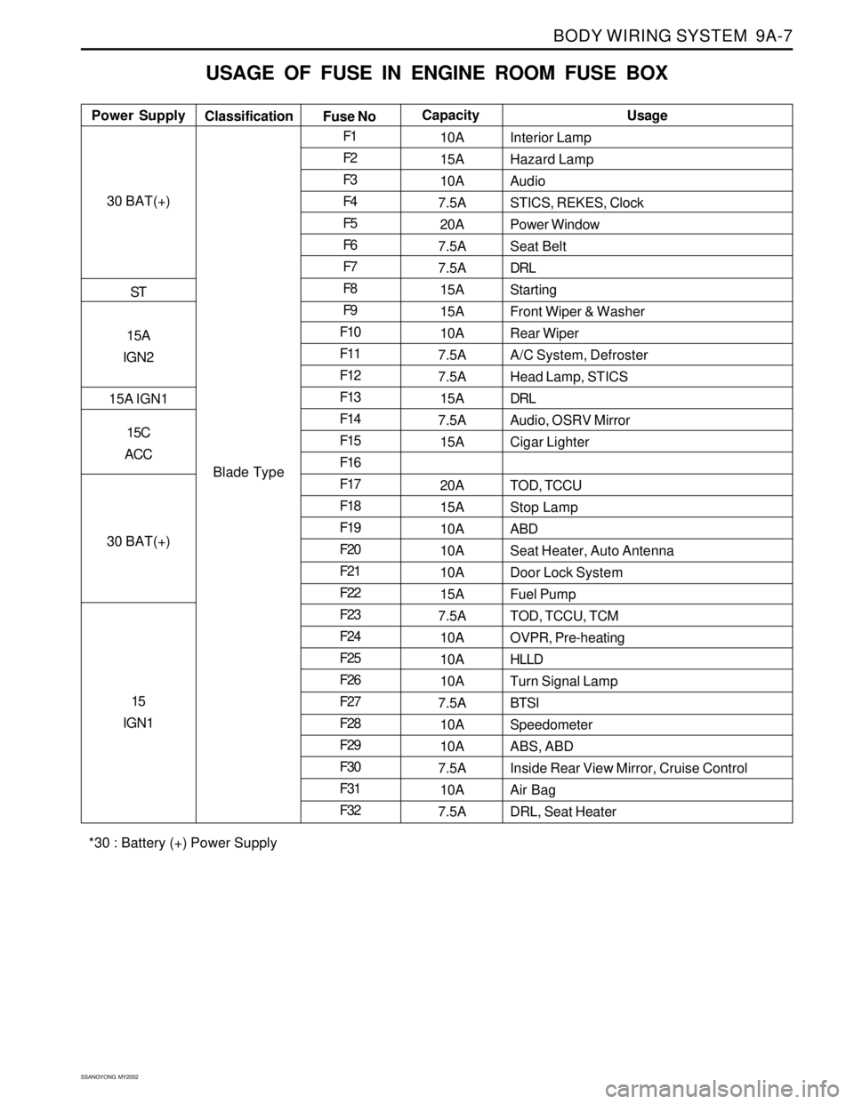
4. Remove the turn signal switch mounting screws.
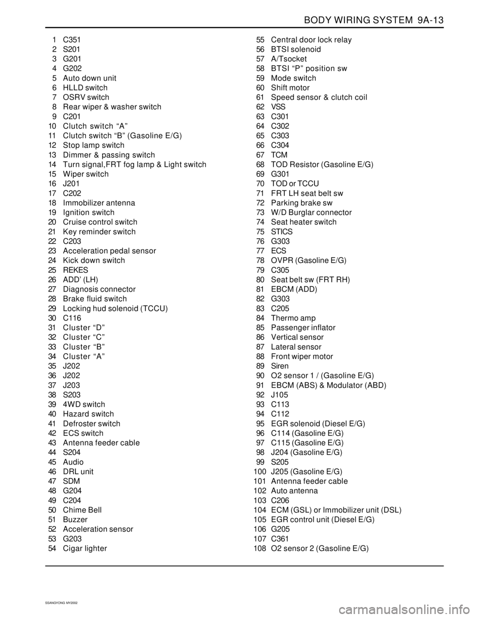
5. Disconnect the turn signal switch connector.
6. Remove the turn signal switch.
Page 1658 of 2053

BODY WIRING SYSTEM 9A-7
SSANGYONG MY2002
USAGE OF FUSE IN ENGINE ROOM FUSE BOX
Interior Lamp
Hazard Lamp
Audio
STICS, REKES, Clock
Power Window
Seat Belt
DRL
Starting
Front Wiper & Washer
Rear Wiper
A/C System, Defroster
Head Lamp, STICS
DRL
Audio, OSRV Mirror
Cigar Lighter
TOD, TCCU
Stop Lamp
ABD
Seat Heater, Auto Antenna
Door Lock System
Fuel Pump
TOD, TCCU, TCM
OVPR, Pre-heating
HLLD
Turn Signal Lamp
BTSI
Speedometer
ABS, ABD
Inside Rear View Mirror, Cruise Control
Air Bag
DRL, Seat Heater Power SupplyUsage
Classification
Fuse NoCapacity
30 BAT(+)
ST
15A
IGN2
15A IGN1
15C
ACC
30 BAT(+)
15
IGN1
Blade TypeF1
F2
F3
F4
F5
F6
F7
F8
F9
F10
F11
F12
F13
F14
F15
F16
F17
F18
F19
F20
F21
F22
F23
F24
F25
F26
F27
F28
F29
F30
F31
F3210A
15A
10A
7.5A
20A
7.5A
7.5A
15A
15A
10A
7.5A
7.5A
15A
7.5A
15A
20A
15A
10A
10A
10A
15A
7.5A
10A
10A
10A
7.5A
10A
10A
7.5A
10A
7.5A
*30 : Battery (+) Power Supply
Page 1662 of 2053

BODY WIRING SYSTEM 9A-11
SSANGYONG MY2002
WIRING HARNESS & CONNECTOR & GROUND LOCATION
W/H ENGINE ROOM
KAA9A070
1 Starting motor
2 G102
3 Damper solenoid (FRT LH)
4 Compressor
5 Wheel speed sensor (FRT LH)
6 Starting motor “ST” terminal connector
7 Canister purge valve (Gasoline E/G)
8 Pre-heating time control unit (Diesel E/G)
9 C109 (Diesel E/G)
10 J102
11 J101
12 G101
13 Turn signal & position lamp (FRT LH)
14 Fog lamp (FRT LH)
15 Head lamp (FRT LH)
16 HLLD (FRT LH)
17 Hood switch
18 Thermo switch (Diesel E/G)
19 LH horn
20 Condenser fan motor-Non A/conditioner
21 Condenser fan motor (LH)22 Resistor
23 RH horn
24 Fog lamp (FRT RH)
25 Condenser fan motor (RH)
26 Head lamp (FRT RH)
27 HLLD (FRT RH)
28 Turn signal & position lamp (FRT RH)
29 G103
30 C110 (Diesel E/G)
31 Alternator B+ (Diesel E/G)
32 J104
33 J103
34 C110 (Gasoline E/G)
35 Alternator B+ (Gasoline E/G)
36 Damper Solenoid (FRT RH)
37 C111
38 Wheel speed sensor (FRT RH)
39 Dual pressure switch
40 Washer motor
41 ADD (FRT RH)
42 C112
43 C113
Page 1664 of 2053

BODY WIRING SYSTEM 9A-13
SSANGYONG MY2002
1 C351
2 S201
3 G201
4 G202
5 Auto down unit
6 HLLD switch
7 OSRV switch
8 Rear wiper & washer switch
9 C201
10 Clutch switch “A”
11 Clutch switch “B” (Gasoline E/G)
12 Stop lamp switch
13 Dimmer & passing switch
14 Turn signal,FRT fog lamp & Light switch
15 Wiper switch
16 J201
17 C202
18 Immobilizer antenna
19 Ignition switch
20 Cruise control switch
21 Key reminder switch
22 C203
23 Acceleration pedal sensor
24 Kick down switch
25 REKES
26 ADD’ (LH)
27 Diagnosis connector
28 Brake fluid switch
29 Locking hud solenoid (TCCU)
30 C116
31 Cluster “D”
32 Cluster “C”
33 Cluster “B”
34 Cluster “A”
35 J202
36 J202
37 J203
38 S203
39 4WD switch
40 Hazard switch
41 Defroster switch
42 ECS switch
43 Antenna feeder cable
44 S204
45 Audio
46 DRL unit
47 SDM
48 G204
49 C204
50 Chime Bell
51 Buzzer
52 Acceleration sensor
53 G203
54 Cigar lighter55 Central door lock relay
56 BTSI solenoid
57 A/Tsocket
58 BTSI “P” position sw
59 Mode switch
60 Shift motor
61 Speed sensor & clutch coil
62 VSS
63 C301
64 C302
65 C303
66 C304
67 TCM
68 TOD Resistor (Gasoline E/G)
69 G301
70 TOD or TCCU
71 FRT LH seat belt sw
72 Parking brake sw
73 W/D Burglar connector
74 Seat heater switch
75 STICS
76 G303
77 ECS
78 OVPR (Gasoline E/G)
79 C305
80 Seat belt sw (FRT RH)
81 EBCM (ADD)
82 G303
83 C205
84 Thermo amp
85 Passenger inflator
86 Vertical sensor
87 Lateral sensor
88 Front wiper motor
89 Siren
90 O2 sensor 1 / (Gasoline E/G)
91 EBCM (ABS) & Modulator (ABD)
92 J105
93 C113
94 C112
95 EGR solenoid (Diesel E/G)
96 C114 (Gasoline E/G)
97 C115 (Gasoline E/G)
98 J204 (Gasoline E/G)
99 S205
100 J205 (Gasoline E/G)
101 Antenna feeder cable
102 Auto antenna
103 C206
104 ECM (GSL) or Immobilizer unit (DSL)
105 EGR control unit (Diesel E/G)
106 G205
107 C361
108 O2 sensor 2 (Gasoline E/G)
Page 1675 of 2053

SECTION 9B
LIGHTING SYSTEM
CAUTION: Disconnect the negative battery cable before removing or installing any electrical unit or when a
tool or equipment could easily come in contact with exposed electrical terminals. Disconnecting this cable
will help prevent personal injury and damage to the vehicle. The ignition must also be in LOCK unless
otherwise noted.
TABLE OF CONTENTS
Description and Operation...................................9B-2
Head Lamps - ON Reminder................................9B-2
Head Lamps........................................................9B-2
Daytime Running Lamps......................................9B-2
Parking and Turn Signal Lamps...........................9B-2
Fog Lamps..........................................................9B-2
Rear Combination Lamps.....................................9B-2
Center High-Mounted Stop Lamp.........................9B-2
Backup Lamps....................................................9B-3
License Plate Lamps ...........................................9B-3
Interior Room Lamps ...........................................9B-3
Luggage Lamps..................................................9B-3
Components Locator............................................9B-4
Diagnostic Information and Procedure...............9B-5
Head Lamps........................................................9B-5
Fog Lamps..........................................................9B-7
Tail Lamps..........................................................9B-8
Interior Room and Luggage Lamps....................9B-11
Door Courtesy Lamps ........................................9B-13
Cigar Lighter......................................................9B-14
Repair Instructions..............................................9B-15
On-Vehicle Service Unit Repair..............................9B-15
Head Lamps......................................................9B-15Front Combination Lamp....................................9B-16
Center High-Mounted Stop Lamp.......................9B-16
Rear Combination Lamps...................................9B-17
Fog Lamps........................................................9B-17
Interior Courtesy Lamp .......................................9B-18
Door Courtesy Lamp ..........................................9B-18
Luggage Lamp..................................................9B-19
License Plate Lamps .........................................9B-19
Specifications.....................................................9B-20
Bulb Usage Chart..............................................9B-20
Fastener Tightening Specifications.....................9B-20
Schematic and Routing Diagrams.....................9B-21
Head Lamp Leveling Device (HLLD) : Gasoline ..9B-21
Head Lamp Leveling Device (HLLD) : Diesel......9B-22
Tail Lamp Relay Circuit Position Lamp,
Tail Lamp, License Lamp................................9B-23
Illumination Switch.............................................9B-24
Turn Signal Lamp...............................................9B-25
Front Fog Lamp.................................................9B-26
Rear Fog Lamp..................................................9B-27
Stop Lamp, BTSI (Brake Transmission
Shift Interlock) - Metal Top..............................9B-28
Stop Lamp, BTSI (Brake Transmission
Shift Interlock) - Soft Top.................................9B-29
Page 1676 of 2053

SSANGYONG MY2002
9B-2 LIGHTING SYSTEM
DESCRIPTION AND OPERATION
HEAD LAMPS - ON REMINDER
When the headlamp switch is in the headlamps-on or
parkinglamps-on positions, voltage is applied to the
chime module. With the headlamp switch on and the
driver’s side door open, the module loses voltage. The
module senses this change. If voltage is still available,
it is applied to sound the chime. The chime can be
turned off by turning the headlamp switch off or closing
the driver’s side door. To replace the chime module,
refer to Section 9E, Instrumentation / Driver Information.
HEAD LAMPS
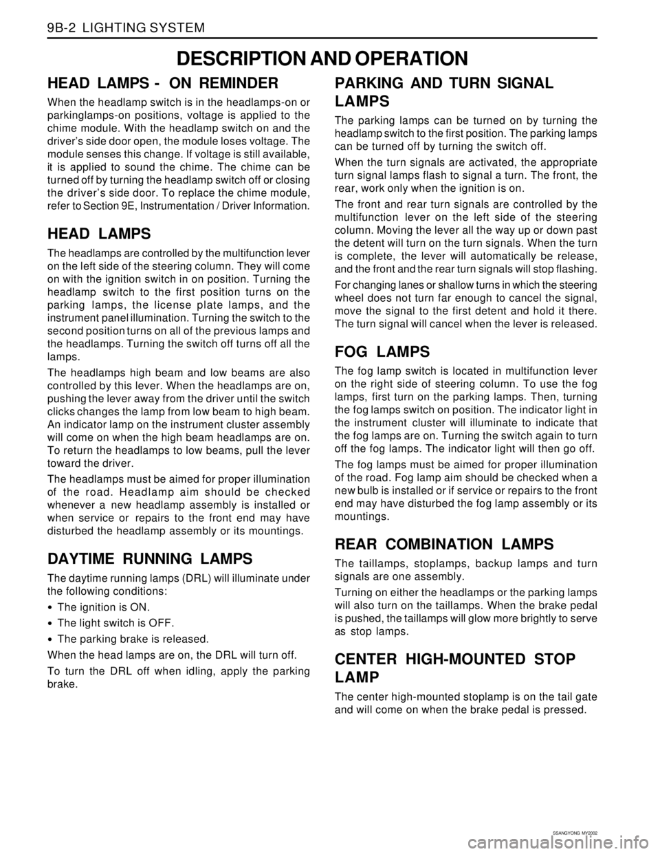
The headlamps are controlled by the multifunction lever
on the left side of the steering column. They will come
on with the ignition switch in on position. Turning the
headlamp switch to the first position turns on the
parking lamps, the license plate lamps, and the
instrument panel illumination. Turning the switch to the
second position turns on all of the previous lamps and
the headlamps. Turning the switch off turns off all the
lamps.
The headlamps high beam and low beams are also
controlled by this lever. When the headlamps are on,
pushing the lever away from the driver until the switch
clicks changes the lamp from low beam to high beam.
An indicator lamp on the instrument cluster assembly
will come on when the high beam headlamps are on.
To return the headlamps to low beams, pull the lever
toward the driver.
The headlamps must be aimed for proper illumination
of the road. Headlamp aim should be checked
whenever a new headlamp assembly is installed or
when service or repairs to the front end may have
disturbed the headlamp assembly or its mountings.
DAYTIME RUNNING LAMPS
The daytime running lamps (DRL) will illuminate under
the following conditions:
The ignition is ON.
The light switch is OFF.
The parking brake is released.
When the head lamps are on, the DRL will turn off.
To turn the DRL off when idling, apply the parking
brake.
PARKING AND TURN SIGNAL
LAMPS
The parking lamps can be turned on by turning the
headlamp switch to the first position. The parking lamps
can be turned off by turning the switch off.
When the turn signals are activated, the appropriate
turn signal lamps flash to signal a turn. The front, the
rear, work only when the ignition is on.
The front and rear turn signals are controlled by the
multifunction lever on the left side of the steering
column. Moving the lever all the way up or down past
the detent will turn on the turn signals. When the turn
is complete, the lever will automatically be release,
and the front and the rear turn signals will stop flashing.
For changing lanes or shallow turns in which the steering
wheel does not turn far enough to cancel the signal,
move the signal to the first detent and hold it there.
The turn signal will cancel when the lever is released.
FOG LAMPS
The fog lamp switch is located in multifunction lever
on the right side of steering column. To use the fog
lamps, first turn on the parking lamps. Then, turning
the fog lamps switch on position. The indicator light in
the instrument cluster will illuminate to indicate that
the fog lamps are on. Turning the switch again to turn
off the fog lamps. The indicator light will then go off.
The fog lamps must be aimed for proper illumination
of the road. Fog lamp aim should be checked when a
new bulb is installed or if service or repairs to the front
end may have disturbed the fog lamp assembly or its
mountings.
REAR COMBINATION LAMPS
The taillamps, stoplamps, backup lamps and turn
signals are one assembly.
Turning on either the headlamps or the parking lamps
will also turn on the taillamps. When the brake pedal
is pushed, the taillamps will glow more brightly to serve
as stop lamps.
CENTER HIGH-MOUNTED STOP
LAMP
The center high-mounted stoplamp is on the tail gate
and will come on when the brake pedal is pressed.
Page 1682 of 2053

SSANGYONG MY2002
9B-8 LIGHTING SYSTEM
Turn Signal Lamps and Hazard Lamps Do Not Work
Step
1
2
3
4
5
6
7
8Action
Check fuses F26, F2 and EF10, EF20.
Is either fuse blown?
Check for a short circuit and repair if necessary
Replace the fuse.
Is the repair complete?
1. Turn the ignition on.
2. Check the voltage at fuse F26, F2 and EF10,
EF20.
Does the battery voltage available at both fuses F26,
F2 and EF10, EF20 equal the specified value?
1. Turn the hazard lamp switch on.
2. Remove each or the inoperative lamps from
socket.
3. Test each lamp socket positive terminal with a
voltmeter.
Does the battery voltage pulsing at the turn-signal,
hazard-lamp socket positive terminal equal the
specified value?
At each bulb socket, use an ohmmeter to check the
ground circuit.
Is the resistance equal to the specified value?
Replace any faulty turn signal/hazard bulbs.
Is the repair complete?
Repair the power supply circuit to fuses.
Is the repair complete?
Repair the open ground circuit.
Is the repair complete?Yes
Go to Step 2
System OK
Go to Step 4
Go to Step 5
Go to Step 6
System OK
System OK
System OKNo
Go to Step 3
-
Go to Step 7
Go to Step 9
Go to Step 8
-
-
- Value(s)
-
-
11 - 14 v
11 - 14 v
0 Ω
-
-
-
TAIL LAMPS
Taillamps Do Not Work
Step
1
2
3
4
5Action
Check fuse EF12.
Is EF12 blown.
1. Check for a short circuit and repair it, if necessary.
2. Replace the fuse.
Is the repair complete?
1. Press the brake pedal down.
2. Check the positive terminals of the bulb sockets
with a test lamp.
Does the test lamp illuminate?
Connect an ohmmeter between ground and the
stoplamp ground terminal.
Is the resistance equal to specified value?
Repair the ground circuit.
Is the repair complete?Yes
Go to Step 2
System OK
Go to Step 2
-
System OKNo
Go to Step 3
-
Go to Step 6
Go to Step 4
- Value(s)
-
-
-
0 Ω
-
Page 1683 of 2053

LIGHTING SYSTEM 9B-9
SSANGYONG MY2002
Trun Signal Lamps and Hazard Lamps Do Not Work (Cont’d)
Step
9
10
11
12
13
14
15
16
17
18
19Action
1. Turn on the hazard switch.
2. Test the blinker unit connector terminal 49 with a
voltmeter.
Does the battery voltage pulsing at the blinker unit
terminal 113 equal the specified value?
1. Turn on the hazard switch.
2. Test the blinker unit connector terminal 31 with a
voltmeter.
Does the battery voltage pulsing at the blinker unit
terminal 31 equal the specified value?
1. Disconnect the blinker unit from the connector.
2. Use an ohmmeter to check between ground and
the connector for terminal 31, 49 of the blinker
unit.
Is the resistance equal to the specified value?
Repair the blinker unit ground connection.
Is the repair complete?
Replace faulty blinker unit.
Is the repair complete?
1. Disconnect the hazard switch connector.
2. Check for voltage at terminal 49.
3. Turn the ignition on.
4. Check for voltage at terminal 111.
Does the battery voltage available at both terminals
equal the specified value?
1. Remove the hazard switch.
2. Turn the hazard switch OFF.
3. Check for continuity between terminals 66 and
111.
4. Turn the hazard switch on.
5. Check for continuity between terminals 66 and
64.
Do both tests show the specified value?
1. Remove the hazard switch.
2. Turn the hazard switch to the on position.
3. Use an ohmmeter to check for continuity between
terminals 112, 62, and 63.
Does the continuity between terminals 112, 62, and
63 equal the specified value?
Replace the faulty hazard switch.
Is the repair complete?
Repair the open circuit between hazard switch
terminal 113 and blinker unit terminal 42.
Is the repair complete?
Repair the open circuit between the hazard switch
and the fuses EF12 or F11.
Is the repair complete?Yes
Go to Step 15
Go to Step 11
Go to Step 13
System OK
System OK
Go to Step 15
Go to Step 18
System OK
System OK
System OK
System OKNo
Go to Step 10
Go to Step 14
Go to Step 12
-
-
Go to Step 19
Go to Step 16
System OK
-
-
- Value(s)
11 - 14 v
11 - 14 v
0 - 0.5 Ω
-
-
11 - 14 v
0 Ω
0 Ω
-
-
-
Page 1684 of 2053

SSANGYONG MY2002
9B-10 LIGHTING SYSTEM
Hazard Lamps Do Not Operate, Turn Signals Are OK (Cont’d)
Step
1
2
3
4
5
6
7
8
9
10Action
Check fuses F26 and F2.
Is fuse EF12 blown?
1. Check for a short circuit and repair if necessary.
2. Replace the fuse.
Is the repair complete?
Use a voltmeter to check for power to fuse F26.
Does the battery voltage available at fuse F26 equal
the value specified?
Repair the power supply circuit to fuse F2.
Is the repair complete?
1. Disconnect the hazard switch connector.
2. Use a voltmeter to check power to the hazard
switch terminal 112.
Does the battery voltage available at connector
terminal 112 equal the value specified?
1. Remove the hazard switch and disconnect it for
testing.
2. Turn the hazard switch to the on position.
3. Test with an ohmmeter between terminals 112
and 113.
Is the resistance equal to the specified value?
1. With the hazard switch still removed and discon-
nected for testing, turn the hazard switch to
the on position.
2. Use an ohmmeter to check between terminals 11,
62, and 63.
Is the resistance equal to the specified value?
Repair the open circuit between the hazard switch
connector and splice connector.
Is the repair complete?
Repair the open circuit between the hazard switch
connector terminal 111 and fuse F26.
Is the repair complete?
Replace the faulty hazard switch.
Is the repair complete?Yes
Go to Step 2
System OK
Go to Step 5
System OK
Go to Step 6
Go to Step 7
Go to Step 8
System Ok
System OK
System OKNo
Go to Step 3
-
Go to Step 4
-
Go to Step 9
Go to Step 10
Go to Step 10
-
-
- Value (s)
-
-
11 - 14 v
-
11 - 14v
0 Ω
0 Ω
-
-
-