SSANGYONG KORANDO 1997 Service Repair Manual
KORANDO 1997
SSANGYONG
SSANGYONG
https://www.carmanualsonline.info/img/67/57502/w960_57502-0.png
SSANGYONG KORANDO 1997 Service Repair Manual
Page 570 of 2053
OM600 ENGINE MECHANICAL 1B3 -- 21
D AEW OO M Y_2000
POLY V-- BELT
1 Nut 23N∙m (17 lb-ft) .......................
2 Tensioning Lever
3Bolt4Spring
5 Tensioning Lever
6PolyV--Belt
Page 571 of 2053
1B3 -- 22 OM600 ENGINE MECHANICAL
D AEW OO M Y_2000
Removal & Installation Procedure
1. Remove the nut.
2. Push the tensioning lever in direction of arrow with a
rod (F12’ 180mm) and pull out the bolt to the rear.
3. Push back the tensioning lever (arrow direction) to
release the spring tension and remove the belt.
4. Install the poly V-- belt beginning at the tensioning
pulley (7).
7 Tensioning Pulley
8 Crankshaft
9 Generator
10 Water Pump
11 Guide Pulley
12 Power Steering Pump
13 Aircon. Compressor
Length of Belt
Length (L)With Air Conditioner2,100 mm
Length (L)Without Air Conditioner2,040 mm
Page 572 of 2053
OM600 ENGINE MECHANICAL 1B3 -- 23
D AEW OO M Y_2000
TENSIONING DEVICE
Preceding Work : Removal of cooling fan
1 Bolt 21N∙m (15 lb-ft) ......................
2 Damper
3 Nut 21N∙m (15 lb-ft) .......................
4 Tensioning Lever
5 Guide Rail Pin
6Bolt
7PolyV--Belt
8 Belt Pulley
9 Bolt 10N∙m (89 lb-in) .....................10 Tensioning Pulley
11 Socket Bolt 29N∙m (21 lb-ft) ................
12 Closing Cover
13 Washer
14 Tensioning Lever
15 Fit Bolt 100N∙m (74 lb-ft) ...................
16 Closing Cover
17 Spring
18 Bolt 20N∙m (15 lb-ft) ......................
Page 573 of 2053
1B3 -- 24 OM600 ENGINE MECHANICAL
D AEW OO M Y_2000
Removal & Installation Procedure
1. Remove the nut.
Installation Notice
Tightening Torque10 N∙m(89lb-in)
2. Push the tensioning lever in direction of arrow with a
rod (F12’ 180mm) and push out the bolt to the rear.
3. Push back the tensioning lever to release the spring
tension and remove the belt.
4. Remove the bolt (9) and then remove the belt pulley
(8).
5. Remove the bolt (1, 18) and take off the damper (2).
Notice
Pay attention to installation position of the damper.
Page 574 of 2053
OM600 ENGINE MECHANICAL 1B3 -- 25
D AEW OO M Y_2000
6. Pull off the tensioning lever (4) from guide rail pin.
7. Remove the spring (17).
Installation Notice
Insert spring (17) with color coding (blue/violet) fac-
ing up.
8. Pry off the closing cover (12) and remove the socket
bolt (11) and then remove the tensioning pulley (10).
Installation Notice
Tightening Torque29 N∙m (21 lb-ft)
9. Pry off the closing cover (16) and remove the fit bolt
(15).
10. Remove the tensioning lever (14) and washer (13).
11. Clean thread in the timing case cover and fit bolt.
Installation Notice
Apply Loctite on thread of fit bolt.
Tightening Torque100 N∙m (74 lb-ft)
12. Installation should follow the removal procedure in
the reverse order.
Page 575 of 2053
1B3 -- 26 OM600 ENGINE MECHANICAL
D AEW OO M Y_2000
POLY V-- BELT ALIGNMENT & INSPECTION
Without Air Conditioner
With Air Conditioner
Page 576 of 2053
OM600 ENGINE MECHANICAL 1B3 -- 27
D AEW OO M Y_2000
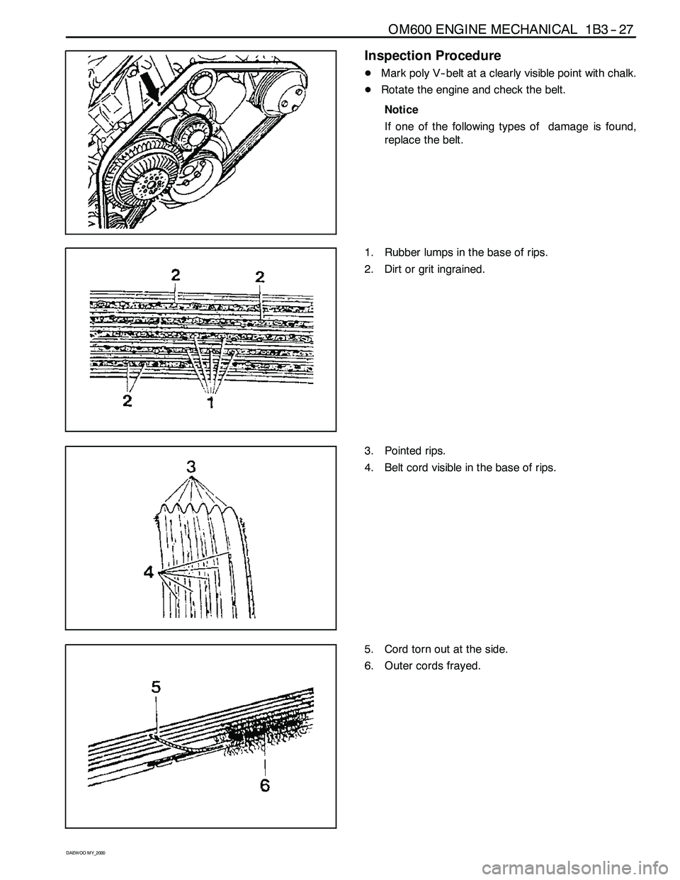
Inspection Procedure
DMark poly V-- belt at a clearly visible point with chalk.
DRotate the engine and check the belt.
Notice
If one of the following types of damage is found,
replace the belt.
1. Rubber lumps in the base of rips.
2. Dirt or grit ingrained.
3. Pointed rips.
4. Belt cord visible in the base of rips.
5. Cord torn out at the side.
6. Outer cords frayed.
Page 577 of 2053
1B3 -- 28 OM600 ENGINE MECHANICAL
D AEW OO M Y_2000
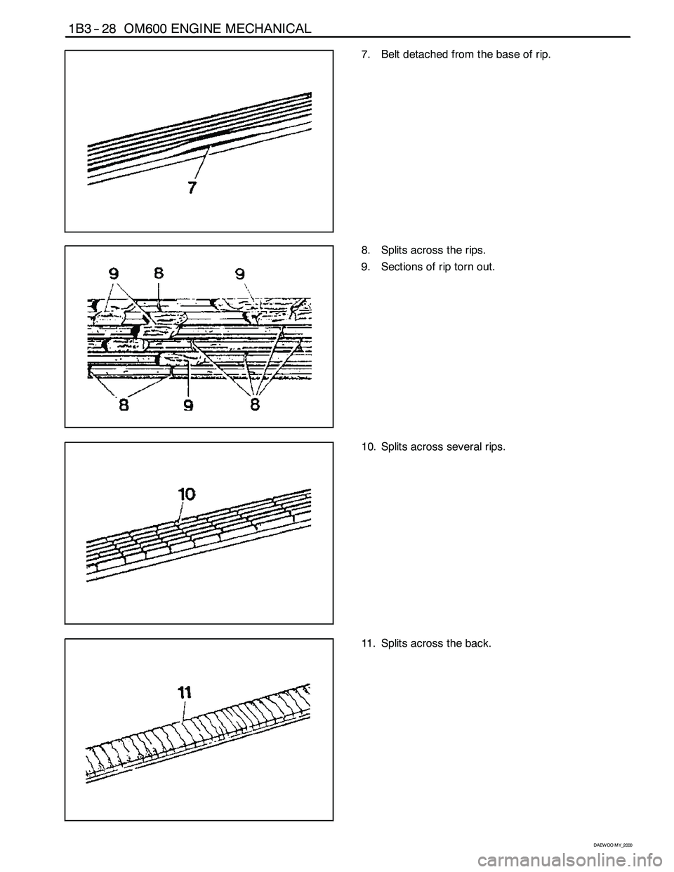
7. Belt detached from the base of rip.
8. Splits across the rips.
9. Sections of rip torn out.
10. Splits across several rips.
11. Splits across the back.
Page 578 of 2053
OM600 ENGINE MECHANICAL 1B3 -- 29
D AEW OO M Y_2000
PRECHAMBER
Preceding Work : Removal of glow plug
Removal of fuel injection nozzle
1 Threaded Ring 130 N∙m (96 lb-ft) ...........
2 Prechamber3 Cylinder Head
Page 579 of 2053
1B3 -- 30 OM600 ENGINE MECHANICAL
D AEW OO M Y_2000
Tools Required
603 589 00 09 00 Serration Wrench
667589036300 SlidingHammer
Removal & Installation Procedure
1. Using the serration wrench (4), remove the threaded
ring (1).
Serration Wrench 603 589 00 09 00
2. Install the sliding hammer into the prechamber.
Sliding Hammer 667 589 03 63 00
3. Remove the perchamber (2).
Notice
After removing the prechamber, cover over the
bores with clean rag.
4. Inspect the prechamber.
Notice
If the prechamber seats in the cylinder head are
leaking or if the prechambers are replaced, the seal-
ing surfaces in the cylinder head must be rema-
chined.


