remote control SSANGYONG KORANDO 1997 Service Repair Manual
[x] Cancel search | Manufacturer: SSANGYONG, Model Year: 1997, Model line: KORANDO, Model: SSANGYONG KORANDO 1997Pages: 2053, PDF Size: 88.33 MB
Page 1317 of 2053

MANUAL TRANSMISSION 5B-9
SSANGYONG MY2002
SEMI-REMOTE KIT DISASSEMBLY AND ASSEMBLY
YAD5B110
1 Remote Shift
2 Shift Lever
3 Shift Inner Boot
4 Lining Shift Socket
5 Control Housing Arm Insulator
6 Control Housing Arm
7 Bushing
8 Shift Rod Link
9 Washer
10 Clip
11 Shift Rod Pin
12 Cover Assembly
13 Shift Tower Cover14 Bolt
15 Breather Hose Bar
16 Control Shift Spring
17 Offset Control Lever
18 Retainer Ring
19 Pin
20 Shift Rail
21 Grove Pin
22 Pin & Clip
23 Joint Assembly
24 Joint Housing
25 Bushing
Page 1320 of 2053

SSANGYONG MY2002
5B-12 MANUAL TRANSMISSION
1 Remote Shift
2 Shift Lever
3 Shift Inner Boot
4 Lining Shift Socket
5 Control Housing Arm Insulator
6 Control Housing Arm
7 Bushing
8 Shift Rod Link
9 Washer
10 Clip
11 Shift Rod Pin
12 Cover Assembly
13 Shift Tower Cover
14 Bolt
15 Bleeder Hose Barb
16 Control Shift Spring
17 Offset Control Lever
18 Retainer Ring
19 Pin
20 Shift Rail
21 Groove Pin
22 Pin and Clip
23 Joint Assembly
24 Joint Housing
25 Bushing
26 Bolt
27 Bolt
28 O-ring
29 Shaft Rail
30 Case Cover
31 Cap Plug
32 Insert
33 Selecter Plate
34 Selecter Arm
35 Inlockter Plate
36 Selecter Arm Pin
37 Selecter Plate
38 Insert
39 Shift Fork
40 Output Shaft
41 Retainer Ring
42 Washer
43 Inner Corn
44 Outer-Race
45 1-2nd Blocking-Ring
46 Output Shaft Assembly
47 Insert
48 Ball
49 Spring
50 Reverse Sliding Gear
51 1-2nd Blocking-Ring
52 Outer Corn Race
53 Inner Corn
54 Sleeve Bearing
55 Sleeve
56 Needle Bearing
57 1st Speed Driven Gear58 Bearing Corn
59 Bearing Cup
60 Thrust Bearing
61 Thrust Race
62 Blocking-Ring
63 Spring
64 Insert
65 Synchronizer Sleeve
66 Spring
67 Blocking-Ring
68 Synchronizer
69 3rd Speed Gear
70 Needle Bearing
71 Spacer
72 Snap Ring
73 Washer
74 2nd Speed Gear
75 Needle Bearing
76 Spacer
77 Synchronizer Sleeve
78 Bearing
79 O-Ring
80 Bearing
81 Corn Bearing
82 Shaft Gear
83 Counter Shaft Gear
84 Corn Bearing
85 Roll Pin
86 Shift 5th Fork
87 Insert
88 Shift Rail
89 Reverse Fork
90 Spring
91 Retainer Ring
92 Shift Lever
93 5th Speed Driven Gear
94 Snap Ring
95 Bearing Cap
96 Shim
97 Rear Retainer
98 Bolt
99 5th Speed Driven Gear
100 Blocking 5th-Ring
101 Hub Bearing
102 Insert
103 Sleeve
104 Spring
105 Spring
106 Synchronizer
107 5th Synchronizer Retainer
108 Snap Ring
109 Oil Ring Funnel
110 Roll Pin
111 Reverse Idler Shaft
112 Reverse Idler Gear
113 O-Ring
114 Cross member Mounting Hole
Page 1322 of 2053

SSANGYONG MY2002
5B-14 MANUAL TRANSMISSION
ON-VEHICLE SERVICE
SEMI-REMOTE KIT
Removal Procedure
1. Remove the control housing arm insulator from the
semi-remote kit.
YAD5B120
YAD5B140
YAD5B130
2. Remove two snap rings and two screws using the
snap ring plier.
Notice: Do not reuse the damaged snap ring.
3. Disconnect the shift rod pin using the punch.
MAINTENANCE AND REPAIR
Page 1323 of 2053

MANUAL TRANSMISSION 5B-15
SSANGYONG MY2002
6. Push down the socket lining’s wing from the
control housing arm and disconnect the socket
lining and shift lever from the semi-remote kit.
YAD5B160
YAD5B170
YAD5B180
7. Remove the control housing arm by rotating the
clip pin.
8. Remove the retainer-ring from the U-joint assembly
using the snap ring plier.
YAD5B150
4. Remove the shift rod link from the semi-remote
kit.
5. Remove four metal bushing from the shift rod.
Page 1326 of 2053

SSANGYONG MY2002
5B-18 MANUAL TRANSMISSION
8. Insert the washer and assemble the snap ring.
YAD5B130
YAD5B260
9. Insert the control housing arm insulator to the semi-
remote kit.
YAD5B250
7. Assemble the shift rod, the shift rail and U-joint
using the pin.
Page 1590 of 2053

SUPPLEMENTAL RESTRAINTS SYSTEM 8B-5
SSANGYONG MY2002
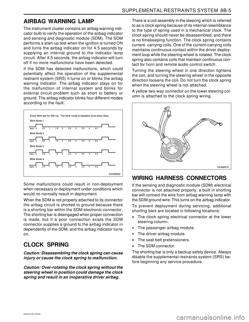
KAA8B060
AIRBAG WARNING LAMP
The instrument cluster contains an airbag warning indi-
cator bulb to verify the operation of the airbag indicator
and sensing and diagnostic module (SDM). The SDM
performs a start-up test when the ignition is turned ON
and turns the airbag indicator on for 4.5 seconds by
supplying an internal ground to the indicator lamp
circuit. After 4.5 seconds, the airbag indicator will turn
off if no more malfunctions have been detected.
If the SDM has detected malfunctions, which could
potentially affect the operation of the supplemental
restraint system (SRS) it turns on or blinks the airbag
warning indicator. The airbag indicator stays on for
the malfunction of internal system and blinks for
external circuit problem such as short to battery or
ground. The airbag indicator blinks four different modes
according to the fault.
Some malfunctions could result in non-deployment
when necessary or deployment under conditions which
would no normally result in deployment.
When the SDM is not properly attached to its connector
the airbag circuit is shorted to ground because there
is a shorting bar within the SDM electronic connector.
The shorting bar is disengaged when proper connection
is made, but if a poor connection exists the SDM
connector supplies a ground to the airbag indicator in
dependently of the SDM, and the airbag indicator turns
on.
CLOCK SPRING
Caution: Disassembling the clock spring can cause
injury or cause the clock spring to malfunction.
Caution: Over-rotating the clock spring without the
steering wheel in position could damage the clock
spring and result in an inoperative driver airbag.There is a coil assembly in the steering which is referred
to as a clock spring because of its internal resemblance
to the type of spring used in a mechanical clock. The
clock spring should never be disassembled, and there
is no timekeeping function. The clock spring contains
current- carrying coils. One of the current-carrying coils
maintains continuous contact within the driver deploy-
ment loop while the steering wheel is rotated. The clock
spring also contains coils that maintain continuous con-
tact for horn and remote audio control switch.
Turning the steering wheel in one direction tightens
the coil, and turning the steering wheel in the opposite
direction loosens the coil. Do not turn the clock spring
when the steering wheel is not attached.
A yellow two-way connector on the lower steering col-
umn is attached to the clock spring wiring.
WIRING HARNESS CONNECTORS
If the sensing and diagnostic module (SDM) electrical
connector is not attached properly, a built in shorting
bar will connect the wire from airbag warning lamp with
the SDM ground wire. This turns on the airbag indicator.
To prevent deployment during servicing, additional
shorting bars are located in following locations:
The clock spring electrical connector at the lower
steering column.
The passenger airbag module.
The driver airbag module.
The seat belt pretensioners.
The SDM connector.
The shorting bar is only a backup safety device. Always
disable the supplemental restraints system (SRS) be-
fore beginning any service procedure.
KAA8B070
Page 1643 of 2053

SUPPLEMENTAL RESTRAINTS SYSTEM 8B-61
SSANGYONG MY2002
KAA8B050
CLOCK SPRING
Removal and installation Procedure
Caution: The SDM can maintain sufficient voltage
to deploy the airbags for 0.15 seconds after the
Ignition is OFF and the airbag fuse has been
removed. If the airbags are not disconnected, service
cannot begin until one minute has passed after
disconnecting power to the SDM. If the airbags are
disconnected, service can begin immediately
without waiting for one-minute time period to
expire. Failure to temporarily disable the SRS
during service result in unexpected deployment,
personal injury, and otherwise unneeded SRS repair.
1. Disconnect the negative battery cable.
2. Remove the driver airbag module. Refer to “Driver
Airbag Module” in this section.
3. Remove the steering wheel. Refer to Section 6E,
Steering Wheel and Column.
4. Remove the steering column cover. Refer to
Section 6E, Steering Wheel and Column.
5. Carefully full the instrument panel lower cover.
6. Remove driver side knee bolster.
7. Disconnect the clock spring, horn and remote
audio control connectors at the lower steering
column.
8. Remove the screws and the clock spring from the
steering shaft.
Installation Notice
Turning the clock spring more than three turns
clockwise or counterclockwise can damage the
spring.
Align the clock spring before installation. Turn
the lobe of the clock spring clockwise to lock
but do not force. Then turn the lobe of clock
spring count clockwise approximately three
turns to the neutral position, with the front of
the wheels straight ahead. Properly align the
pointed marks on the components of the clock
spring.
9. Installation should follow the removal procedure
in the reverse order.
Caution: If the clock spring is not properly
aligned, the steering wheel may not be able to
rotate completely during a turn. Restricted
turning ability can cause the vehicle to crash.
Improper alignment of the clock spring also may
make the supplemental restraint system (SRS)
inoperative, preventing the airbag from
deploying during crash. Both of the out comes
can result in injury.
Tightening Torque 4 Nm (35 lb-in)
Page 1784 of 2053

SSANGYONG MY2002
9L-2 GLASS AND MIRRORS
DESCRIPTION AND OPERATION
STATIONARY GLASS
Stationary glass consists of all the glass on the vehicle
which is immovable within its frame, such as the wind
shield glass, the back glass, the quarter window, and
the inside rearview mirror.
INSIDE REARVIEW MIRROR
The inside rearview mirror can be manually adjusted
up/down, and left/right.
OUTSIDE REARVIEW MIRRORS
The outside rearview mirrors are equipped with a remote
control mirror. The electric control outside rearviewmirror
can be adjusted by an electric control switch on the
instrument panel
Page 1849 of 2053

SSANGYONG MY2002
9T1-2 REMOTE KEYLESS ENTRY AND ANTI-THEFT SYSTEM
DESCRIPTION AND OPERATION
REMOTE KEYLESS ENTRY AND
ANTI-THEFT SYSTEM
The remote keyless entry and anti-theft system can
perform the following functions:
•Remotely lock and unlock the vehicle doors by
means of a hand-held, high-frequency transmitter.
Sense intrusion into the vehicle through the doors
or the hood.
Activate a warning if an intrusion is detected.
Automatically relock the doors if thedoor or the
tail gate is not opened within 30 seconds after the
vehicle has been unlocked by remote keyless
entry.
Help the driver find the vehicle in a parking area.
The remote keyless entry system consist of the
following components:
STICS.
Remote keyless entry system receiver.
Hand-held transmitter.
Tailgate open switch.
Door contact switch.
Siren.
Hood open switch
Key reminder switch.
Antenna.
STICS can perform the following functions:
1. Wiper INT sening vehicle speed.
By operating INT tiem control volume, variable
time will be changed within 1.5-20 seconds
2. Washer relating wiper.
3. Dimming room lamp.
When room lamp is coupled with door, it truns on
if door is opened. After closing the door it
maintains 2 seconds of lighting and dims off
whithin 3 seconds.
4. Time delayed power window control.
Power window can be operated within 30 seconds
after truning the IGN 1 switch from ON to OFF. If
driver/passenger’s door is opened within the 30
seconds from that moment.
5. Rear defogger timer.
The rear defogger will be operated for 12 min. by
turning ON the defogger switch while engine is
running.
Defogger will be stopped by pushing the switch
again.
The defogger will be operated 6 mim, if push ON
the switch within 10 min. after 12 min. of operation.6. Seat belt waring.
The warning lamp will be turned on for about 6
sec. With an intermittent chime bell when the IGN.
Switch is ON unless fastening the seat belt.
7. parking brake warning.
The indicator lamp will flash if drive while the
parking brake is applied.
8. Tail lamp lighting warning.
When the driver’s door is opened while the tail
lamp is still ON, the buzzer operates intermittently.
In this condition, the door will be automatically
unlock when it locked.
9. Door ajar warning.
The indicator lamp will be blinking when the door
is not closed completely and driving.
10. IGN key reminder.
The chime will be operated intermittently if the
driver’s door is opened while the IGN key is still
remain-ing in the ignition switch. In this condition,
the door will be automatically unlocked when it
locked.
11. Central door lock.
All doors will be locked/unlocked by locking/
unlocking the driver’s or passenger’s door.
12. coupled with REKES.
Being coupled with REKES (remote keyless entry
system), all doors will be locked/unlocked
according to signals of transmitter when the
ignition key is not inserted.
13. iginition key hole illumination.
coupled with door switch, ignition key hole
illumination lamp will trun on when the driver ’s
door is opened and will dim off after 10 sec. After
closing the door.
14. Auto door lock.
All doors will be locked automatically if the vehicle
speed reaches 50 km/h though the doors are in
unlock.
15. Auto door unlock.
All doors will be automatically unlock if the vehicle
crashes while driving (over 15km/h).
Operate the burglar alarm.
1. Burglar alarm must operate immediately when the
door, tailgate or hood is opened with improper
ways after all doors and hood were closed and
continued this status for 1 seconds.
2. If the tailgate is opened by key when the system
is on the burglar alarm cindition, the sysem must
be changed to the second burglar alarm condition
frim normal condition.
Page 1858 of 2053

SSANGYONG MY2002
9T2-2 IMMOBILIZER SYSTEM
DESCRIPTION AND OPERATION
Immobilizer is a device disabling vehicle ignition unless
a speific key is used and designed to help prevent
vehicle theft.
Immobilizer is comprised of two devices, a key with
encoded transponder and engine control unit (ECU)
with the same encoding of the transponder. When a
key is inserted into the key hole to start vehicle and
turned to ‘ON’, the ECU reads and decodes the
transponder code and, if the same, starts the engine,
it is called immobilizer. It means immobilizer system
disables starting by stopping fuel supply if the code
in the transponder does not match the code stored in
ECU each other.
Notice:
If vehicle is equipped with immobilizer system and
the engine cranks normally but not start, check
immobilizer system first rather than ignition and
other electrical systems because it can be
disabled fuel supply of injectors by ECU due to
defective immobilizer system.
Programming of the immobilizer system will be
performed by authorized personnel only. If
following defective codes for immobilizer system
appear during diagnosis of vehicle with SCANNER,
ask immobilizer programming to authorized
personnel and actual programming should be
performed by authorized per-sonnel only.
Display of defectives relevant to immobilizer
system : SCANNER
1. No communication with transponder
2. No immobilizer programming
The transponder in the key can be damaged by
shocks of dropping or hitting other objectives, so
handle it with care.
Each supplied key has programming of code on
its own. Accordingly if ECU needs to be replaced,
replace the transponder in the key.
The vehicle equipped with immobilizer system will
never be started with remote ignition device, so
do not attempt to install it.
The immobilizer system will never be removed from
the vehicle. So never attempt to remove it to install
a remote ignition device or others.
If engine does not start during service, use every
key to start the engine and then check immobilizer
sys-tem finally.
Cases that requires immobilizer
programming
1. Replacement ECU
In this case, replace the every transponder of the
key at once.
2. Replacement of the transponder
3. Additional key for lost 1 or 2 keys
1) Clear all codes for current keys from the ECU
2) When using current key : clear code of the trans-
ponder and re-program it
3) Additional (purchased) key : perform programming
4. When lost all keys
1) Clear all memorized key codes from the ECU
2) Replace the key and key set
3) Immobilizer programming