ecm SSANGYONG KORANDO 1997 Service Workshop Manual
[x] Cancel search | Manufacturer: SSANGYONG, Model Year: 1997, Model line: KORANDO, Model: SSANGYONG KORANDO 1997Pages: 2053, PDF Size: 88.33 MB
Page 235 of 2053

1F1 -- 72 M162 ENGINE CONTROLS
D AEW OO M Y_2000
COOLING FAN
KAB1F290
Failure
CodeDescriptionTrouble AreaMaintenance Hint
44Cooling fan (HI) relay
short circuit to powerCooling fan short circuit to
powerDInspection the Engine Control Module
(ECM) pin 35 about short circuit or
openwithbadcontact
45
Cooling fan (HI) relay
short circuit to ground or
openCooling fan short circuit to
ground or open
openwithbadcontact
DInspection the power source
DInspection the cooling fan
DInspection the ECM
Circuit Description
Ignition voltage is supplied directly to the cooling fan relay coil. The ECM controls the relay by grounding the control
circuit. When the ECM is commanding a command ON, the voltage of the control circuit should be low (near 0 volt).
When the ECM is commanding the control circuit should be high (near battery voltage). If the fault detection circuit
senses a voltage other than what is expected, the fault line status will change causing the fault code to set.
Page 236 of 2053

M162 ENGINE CONTROLS 1F1 -- 73
D AEW OO M Y_2000
A/C COMPRESSOR RELAY
KAB1F290
Failure
CodeDescriptionTrouble AreaMaintenance Hint
228A/C compressor relay
short circuit to battery
WhenmalfunctionofA/C
DMonitoring the actual operation
through scan tool
DInspection the Engine Control Module
(ECM)pin44aboutshortcircuitor
229
A/c compressor relay
short circuit to ground or
open
When malfunction ofA/C
compressor control
(ECM)pin44aboutshortcircuitor
open with bad contact
DInspection the relay short circuit or
open
DInspection the ECM
Circuit Description
When the ECM detects that A/C has been requested, the ECMwill activated the A/C clutch relay. When the relay has
been activated, voltage should be present at both the A/C clutch relay and A/C switch circuit at ECM.
Page 237 of 2053

1F1 -- 74 M162 ENGINE CONTROLS
D AEW OO M Y_2000
CRUISE CONTROL SWITCH
KAB1F300
Failure
CodeDescriptionTrouble AreaMaintenance Hint
129
Cruise control “OFF”
due to message counter
failureCruise control system
Message counter fault
130Vehicle speed signal
failureWhen malfunction of
auto-- cruise systemDMonitoring the actual recognition
status and vehicle speed signal
throughscantool
131Vehicle speed signal
failure
autocruisesystem
Implausible condition of
vehicle speed signal.through scan tool
DInspection the Engine Control Module
(ECM)pin52,53,54,55,57about
132Cruise control lever
failureCruise control lever defective
(ECM)pin52,53,54,55,57about
short circuit or open with bad contact
DInspection the CAN and ABS
133Cruise control
acceleration failureCruise control system
Implausible condition of
acceleration signal
InspectiontheCANandABS
DInspection the cruise control lever
switch
DInspection the ECM
134Cruise control
deceleration failureCruise control system
Implausible condition of
deceleration signal
p
Circuit Description
Cruise control is an automatic speed control system that maintain a desired driving speed without using the accelerator
pedal. The vehicle speed must be greater than 40 km/h to engage cruise control.
Page 238 of 2053

M162 ENGINE CONTROLS 1F1 -- 75
D AEW OO M Y_2000
TRACTION CONTROLSYSTEM (TCS)
KAB1F310
Failure
CodeDescriptionTrouble AreaMaintenance Hint
150TCS input signal short
circuit to batteryTCS short circuit to powerDInspection the Engine Control Module
(ECM) pin 45 about short circuit or
openwithbadcontact
151TCS input signal short
circuit to ground or openTCS short circuit to ground or
open
openwithbadcontact
DInspection the TCS lamp of I/P cluster.
DInspection the ECM
Circuit Description
Battery voltage is supplied to the TCS warning lamp with the ignition in ON and START. The warning lamp can be
activated only by the Electrical Brake Control Module (EBCM) internally supplying ground to terminal 32. If the TCS
input circuit is open or short, this failure codewill be set.
Page 239 of 2053

1F1 -- 76 M162 ENGINE CONTROLS
D AEW OO M Y_2000
RESONANCE FLAP
KAB1F160
Failure
CodeDescriptionTrouble AreaMaintenance Hint
198Resonance flap short
circuit to batteryResonance flap short circuit
to power
DMonitoring the actual operational
status and vehicle speed signal
through scan tool
DInspection the Engine Control Module
(ECM) pin 97 about short circuit or
openwithbadcontact
199Resonance flap short
circuit to ground or openResonance flap short circuit
to ground or open
openwithbadcontact
DInspection the power source short
circuit or open to resonance flap
DInspection the resonance flap solenoid
and hardware
DInspection the ECM
Circuit Description
A pneumatically actuated resonance flap is located on the intake manifold, andwill beopened and closed by load,
which operates resonance flap according to engine and controlled by ECM and rpm.
Resonance flap is closed at idle/partial load (less than 3,800/rpm). The switch valvewill be adjusted by ECM and reso-
nance flapwill be closed. By increasing air flow passage through dividing intake air flow toward both air collection
housing. This leads to a significant increase in the torque in the lower speed range.
Resonance flap is open at full load (over 3,800/rpm). The switch valvewill not be adjusted by ECM and resonance flap
will beopen. The collected air in the air collection housingwill not be divided and intake air passage will be shorten.
Page 240 of 2053

M162 ENGINE CONTROLS 1F1 -- 77
D AEW OO M Y_2000
STOP LAMP SWITCH
KAB1F320
Failure
CodeDescriptionTrouble AreaMaintenance Hint
135Stop lamp switch failure
When malfunction of stop
lamp switch – implausible
condition of stop lamp signal
input
DMonitoring the actual operational
status and vehicle speed signal
through scan tool
DInspection the Engine Control Module
(ECM) pin 49 about short circuit or
open with bad contact
DInspection the contact condition of
stop lamp switch
DInspection the ECM
Circuit Description
The stop lamp switch is normally opened. When the ignition switch ON and brake ON, the battery voltage is supplied to
the ECM. A scan tool should display ON when brake pedal is depressed and should read OFF with brake pedal rele-
ased.
Page 241 of 2053

1F1 -- 78 M162 ENGINE CONTROLS
D AEW OO M Y_2000
ENGINE RPM
KAB1F330
Failure
CodeDescriptionTrouble AreaMaintenance Hint
32
Engine rpm output
circuit short circuit to
battery
When short circuit to battery
DMonitoring the actual rpm in cluster
DInspection the Engine Control Module
(ECM) pin 60 about short circuit or
open
33
Engine rpm output
circuit short circuit to
ground or openWhen short circuit to ground
or open
open
DInspection the cluster panel board
circuit
DInspection the ECM
Page 243 of 2053

1F1 -- 80 M162 ENGINE CONTROLS
D AEW OO M Y_2000
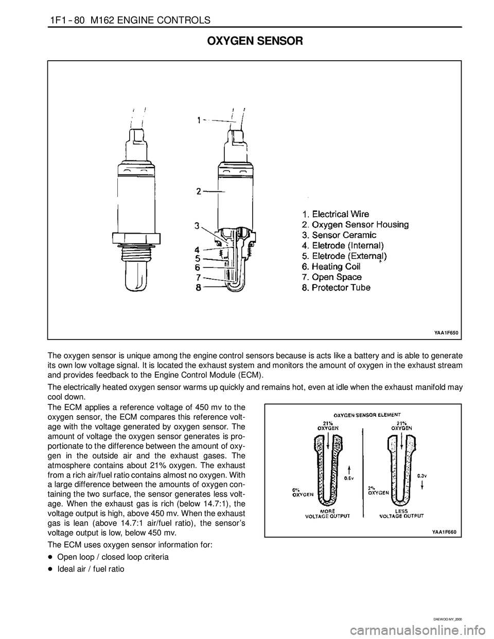
OXYGEN SENSOR
YAA1F650
The oxygen sensor is unique among the engine control sensors because is acts like a battery and is able to generate
its own low voltage signal. It is located the exhaust system and monitors the amount of oxygen in the exhaust stream
and provides feedback to the Engine Control Module (ECM).
The electrically heated oxygen sensor warms up quickly and remains hot, even at idle when the exhaust manifold may
cool down.
The ECM applies a reference voltage of 450 mv to the
oxygen sensor, the ECM compares this reference volt-
age with the voltage generated by oxygen sensor. The
amount of voltage the oxygen sensor generates is pro-
portionate to the difference between the amount of oxy-
gen in the outside air and the exhaust gases. The
atmosphere contains about 21% oxygen. The exhaust
from a rich air/fuel ratio contains almost no oxygen. With
a large difference between the amounts of oxygen con-
taining the two surface, the sensor generates less volt-
age. When the exhaust gas is rich (below 14.7:1), the
voltage output is high, above 450 mv. When the exhaust
gas is lean (above 14.7:1 air/fuel ratio), the sensor ’s
voltage output is low, below 450 mv.
The ECM uses oxygen sensor information for:
DOpen loop / closed loop criteria
DIdeal air / fuel ratio
YAA1F660
Page 245 of 2053

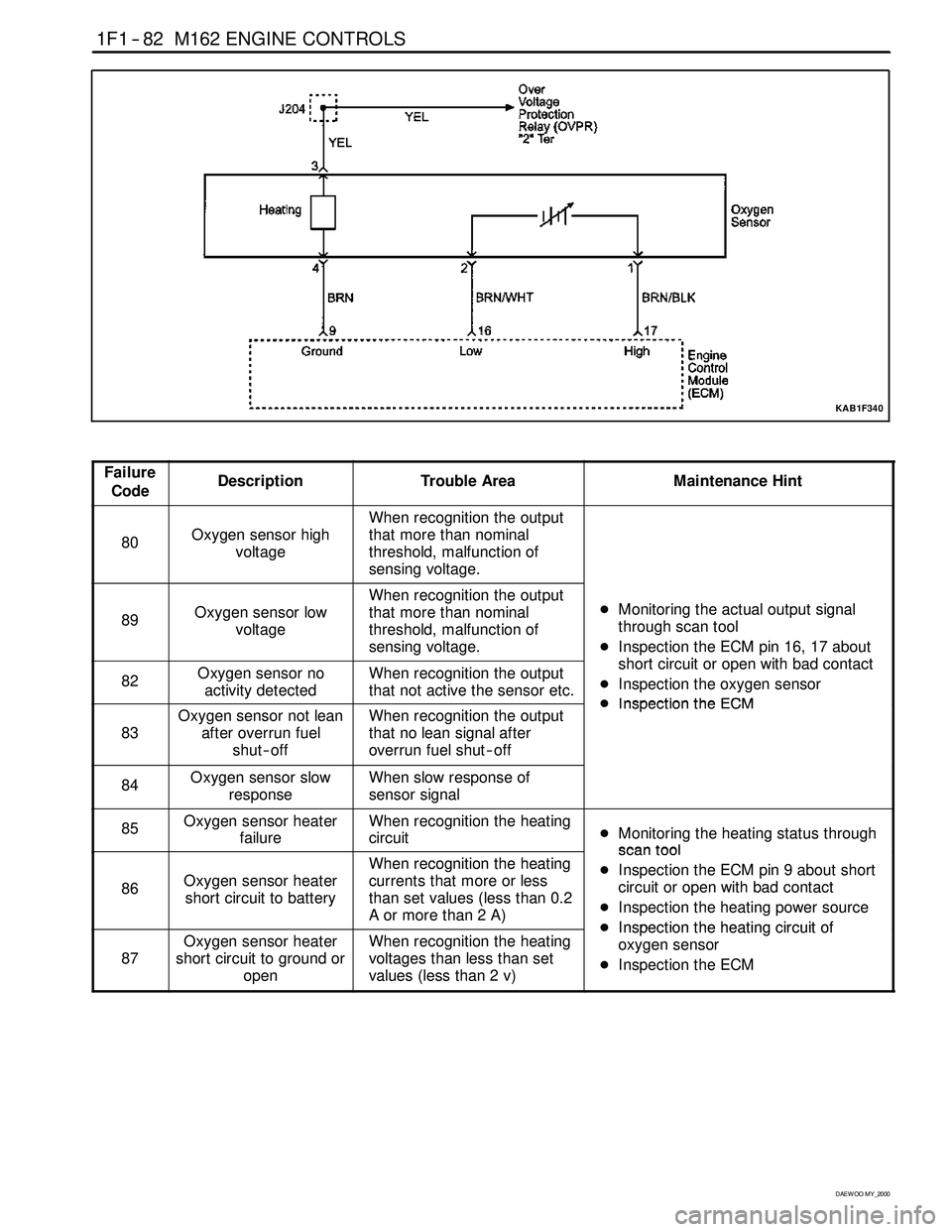
1F1 -- 82 M162 ENGINE CONTROLS
D AEW OO M Y_2000
KAB1F340
Failure
CodeDescriptionTrouble AreaMaintenance Hint
80Oxygen sensor high
voltage
When recognition the output
that more than nominal
threshold, malfunction of
sensing voltage.
89Oxygen sensor low
voltage
When recognition the output
that more than nominal
threshold, malfunction of
sensing voltage.DMonitoring the actual output signal
through scan tool
DInspection the ECM pin 16, 17 about
htiitithbdtt
82Oxygen sensor no
activity detectedWhen recognition the output
that not active the sensor etc.short circuit or open with bad contact
DInspection the oxygen sensor
DInspectiontheECM
83
Oxygen sensor not lean
after overrun fuel
shut -- offWhen recognition the output
that no lean signal after
overrun fuel shut -- offDInspectiontheECM
84Oxygen sensor slow
responseWhen slow response of
sensor signal
85Oxygen sensor heater
failureWhen recognition the heating
circuitDMonitoring the heating status through
scantool
86Oxygen sensor heater
short circuit to battery
When recognition the heating
currents that more or less
than set values (less than 0.2
Aormorethan2A)scantool
DInspection the ECM pin 9 about short
circuit or open with bad contact
DInspection the heating power source
DInspectiontheheatingcircuitof
87
Oxygen sensor heater
short circuit to ground or
openWhen recognition the heating
voltages than less than set
values (less than 2 v)DInspectiontheheating circuitof
oxygen sensor
DInspection the ECM
Page 246 of 2053

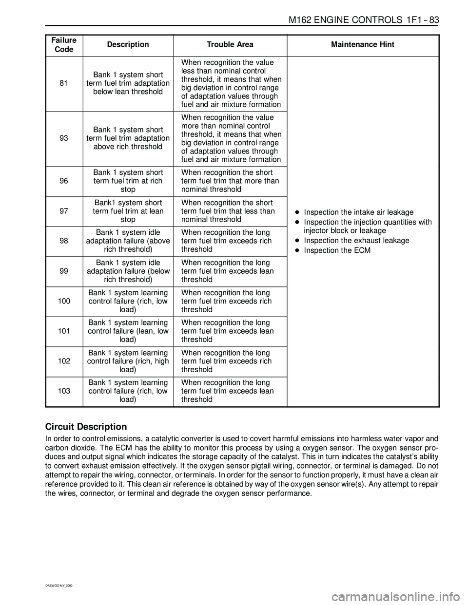
M162 ENGINE CONTROLS 1F1 -- 83
D AEW OO M Y_2000
Failure
CodeDescriptionTrouble AreaMaintenance Hint
81
Bank 1 system short
term fuel trim adaptation
below lean threshold
When recognition the value
less than nominal control
threshold, it means that when
big deviation in control range
of adaptation values through
fuel and air mixture formation
93
Bank 1 system short
term fuel trim adaptation
above rich threshold
When recognition the value
more than nominal control
threshold, it means that when
big deviation in control range
of adaptation values through
fuel and air mixture formation
96
Bank 1 system short
term fuel trim at rich
stopWhen recognition the short
term fuel trim that more than
nominal threshold
97
Bank1 system short
term fuel trim at lean
stopWhen recognition the short
term fuel trim that less than
nominal threshold
DInspection the intake air leakage
DIns
pection the injectionquantities with
98
Bank 1 system idle
adaptation failure (above
rich threshold)When recognition the long
term fuel trim exceeds rich
threshold
DInspectiontheinjectionquantitieswith
injector block or leakage
DInspection the exhaust leakage
DInspection the ECM
99
Bank 1 system idle
adaptation failure (below
rich threshold)When recognition the long
term fuel trim exceeds lean
threshold
p
100
Bank 1 system learning
control failure (rich, low
load)When recognition the long
term fuel trim exceeds rich
threshold
101
Bank 1 system learning
control failure (lean, low
load)When recognition the long
term fuel trim exceeds lean
threshold
102
Bank 1 system learning
control failure (rich, high
load)When recognition the long
term fuel trim exceeds rich
threshold
103
Bank 1 system learning
control failure (rich, low
load)When recognition the long
term fuel trim exceeds lean
threshold
Circuit Description
In order to control emissions, a catalytic converter is used to covert harmful emissions into harmless water vapor and
carbon dioxide. The ECM has the ability to monitor this process by using a oxygen sensor. The oxygen sensor pro-
duces and output signal which indicates the storage capacity of the catalyst. This in turn indicates the catalyst’s ability
to convert exhaust emission effectively. If the oxygen sensor pigtail wiring, connector, or terminal is damaged. Do not
attempt to repair the wiring, connector, or terminals. In order for the sensor to function properly, it must have a clean air
reference provided to it. This clean air reference is obtained by way of the oxygen sensor wire(s). Any attempt to repair
the wires, connector, or terminal and degrade the oxygen sensor performance.