Pig tail SSANGYONG KORANDO 1997 Service Repair Manual
[x] Cancel search | Manufacturer: SSANGYONG, Model Year: 1997, Model line: KORANDO, Model: SSANGYONG KORANDO 1997Pages: 2053, PDF Size: 88.33 MB
Page 177 of 2053

1F1 -- 14 M162 ENGINE CONTROLS
D AEW OO M Y_2000
DIAGNOSIS
FAILURE CODE DIAGNOSIS
CLEARING FAILURE CODES
Notice:To prevent Engine Control Module (ECM) damage, the key must be OFF when disconnecting or reconnecting
the power to the ECM (for example battery cable, ECM pigtail connector, ECM fuse, jumper cables, etc.)
Parameters listed in the table may not be exactly the same as your reading due to the type of instrument or other
factors. If a failure code is displayed during the “TROUBLE CODE” in scan tool check mode, check the circuit for the
code listed in the table below. For details of each code, turn to the page referred to under the “See Page” for the re-
spective “Failure Code” in the below table.
Failure codes should be cleared after repairs have been completed.
FAILURE CODES TABLE
Failure
codeSee
PageDescription
001F1 -- 66Engine coolant temperature sensor low voltage
011F1 -- 66Engine coolant temperature sensor high voltage
021F1 -- 66Engine coolant temperature sensor plausibility
031F1 -- 62Intake air temperature sensor low voltage
041F1 -- 62Intake air temperature sensor high voltage
051F1 -- 62Intake air temperature sensor plausibility
061F1 -- 66Engine coolant temperature insufficient for closed loop fuel control
081F1 -- 38System voltage too low
091F1 -- 62Mass air flow sensor plausibility
101F1 -- 62Mass air flow sensor low voltage
111F1 -- 62Mass air flow sensor high voltage
171F1 -- 23Crankshaft position sensor signal failure (no engine revolution signal)
181F1 -- 23Crankshaft position sensor signal failure (rpm > max. value)
191F1 -- 27Camshaft position senosr signal : No.1 cylinder recognition failure
201F1 -- 23Crankshaft position sensor signal failure (gap recognition failure)
211F1 -- 90Transmission coding failure
231F1 -- 88CAN communication failure : ASR/MSR
241F1 -- 88CAN communication failure : ABS
251F1 -- 94Communication with transponder missing
261F1 -- 88CAN communication failure : TCU (A/T only)
271F1 -- 88CAN communication failure : TOD (E32 only)
291F1 -- 89CAN communication failure : ID 200h not plausible
301F1 -- 89CAN communication failure : ID 208h not plausible
311F1 -- 89CAN communication failure : communication initialization failure
321F1 -- 78Engine rpm output circuit short circuit to battery
331F1 -- 78Engine rpm output circuit short circuit to ground or open
341F1 -- 43Fuel pump relay short circuit to battery
351F1 -- 43Fuel pump relay short circuit to ground or open
Page 246 of 2053

M162 ENGINE CONTROLS 1F1 -- 83
D AEW OO M Y_2000
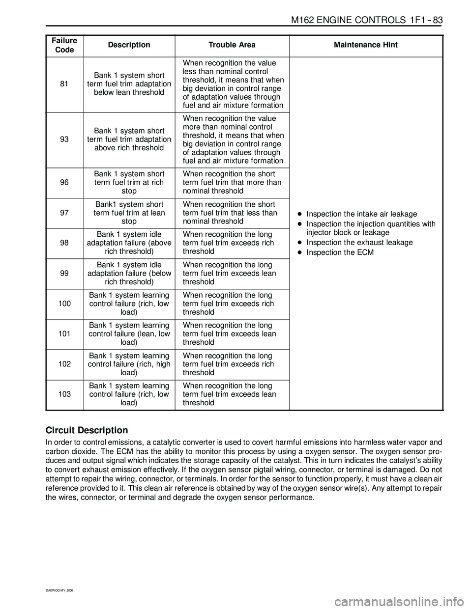
Failure
CodeDescriptionTrouble AreaMaintenance Hint
81
Bank 1 system short
term fuel trim adaptation
below lean threshold
When recognition the value
less than nominal control
threshold, it means that when
big deviation in control range
of adaptation values through
fuel and air mixture formation
93
Bank 1 system short
term fuel trim adaptation
above rich threshold
When recognition the value
more than nominal control
threshold, it means that when
big deviation in control range
of adaptation values through
fuel and air mixture formation
96
Bank 1 system short
term fuel trim at rich
stopWhen recognition the short
term fuel trim that more than
nominal threshold
97
Bank1 system short
term fuel trim at lean
stopWhen recognition the short
term fuel trim that less than
nominal threshold
DInspection the intake air leakage
DIns
pection the injectionquantities with
98
Bank 1 system idle
adaptation failure (above
rich threshold)When recognition the long
term fuel trim exceeds rich
threshold
DInspectiontheinjectionquantitieswith
injector block or leakage
DInspection the exhaust leakage
DInspection the ECM
99
Bank 1 system idle
adaptation failure (below
rich threshold)When recognition the long
term fuel trim exceeds lean
threshold
p
100
Bank 1 system learning
control failure (rich, low
load)When recognition the long
term fuel trim exceeds rich
threshold
101
Bank 1 system learning
control failure (lean, low
load)When recognition the long
term fuel trim exceeds lean
threshold
102
Bank 1 system learning
control failure (rich, high
load)When recognition the long
term fuel trim exceeds rich
threshold
103
Bank 1 system learning
control failure (rich, low
load)When recognition the long
term fuel trim exceeds lean
threshold
Circuit Description
In order to control emissions, a catalytic converter is used to covert harmful emissions into harmless water vapor and
carbon dioxide. The ECM has the ability to monitor this process by using a oxygen sensor. The oxygen sensor pro-
duces and output signal which indicates the storage capacity of the catalyst. This in turn indicates the catalyst’s ability
to convert exhaust emission effectively. If the oxygen sensor pigtail wiring, connector, or terminal is damaged. Do not
attempt to repair the wiring, connector, or terminals. In order for the sensor to function properly, it must have a clean air
reference provided to it. This clean air reference is obtained by way of the oxygen sensor wire(s). Any attempt to repair
the wires, connector, or terminal and degrade the oxygen sensor performance.
Page 266 of 2053

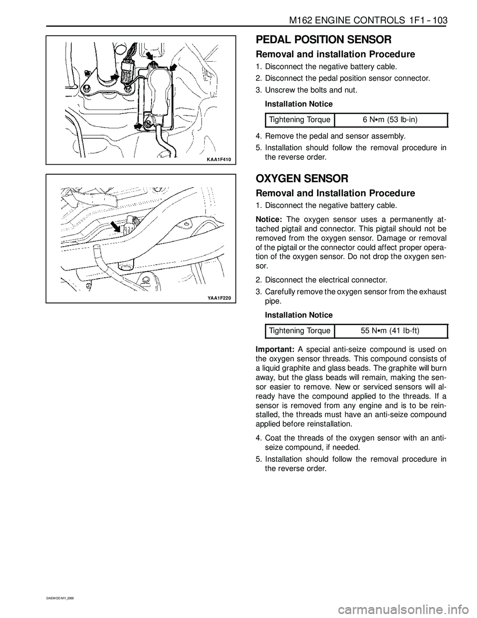
M162 ENGINE CONTROLS 1F1 -- 103
D AEW OO M Y_2000
KAA1F410
PEDAL POSITION SENSOR
Removal and installation Procedure
1. Disconnect the negative battery cable.
2. Disconnect the pedal position sensor connector.
3. Unscrew the bolts and nut.
Installation Notice
Tightening Torque
6NSm (53 lb-in)
4. Remove the pedal and sensor assembly.
5. Installation should follow the removal procedure in
the reverse order.
YAA1F220
OXYGEN SENSOR
Removal and Installation Procedure
1. Disconnect the negative battery cable.
Notice:The oxygen sensor uses a permanently at-
tached pigtail and connector. This pigtail should not be
removed from the oxygen sensor. Damage or removal
of the pigtail or the connector could affect proper opera-
tion of the oxygen sensor. Do not drop the oxygen sen-
sor.
2. Disconnect the electrical connector.
3. Carefully remove the oxygen sensor from the exhaust
pipe.
Installation Notice
Tightening Torque
55 NSm (41 Ib-ft)
Important:A special anti-seize compound is used on
the oxygen sensor threads. This compound consists of
a liquid graphite and glass beads. The graphitewill burn
away, but the glass beadswill remain, making the sen-
sor easier to remove. New or serviced sensors will al-
ready have the compound applied to the threads. If a
sensor is removed from any engine and is to be rein-
stalled, the threads must have an anti-seize compound
applied before reinstallation.
4. Coat the threads of the oxygen sensor with an anti-
seize compound, if needed.
5. Installation should follow the removal procedure in
the reverse order.
Page 436 of 2053

1F2 -- 14 M161 ENGINE CONTROLS
D AEW OO M Y_2000
DIAGNOSIS
FAILURE CODE DIAGNOSIS
CLEARING FAILURE CODES
Notice:To prevent Engine Control Module (ECM) damage, the key must be OFF when disconnecting or reconnecting
the power to the ECM (for example battery cable, ECM pigtail connector, ECM fuse, jumper cables, etc.)
Parameters listed in the table may not be exactly the same as your reading due to the type of instrument or other
factors. If a failure code is displayed during the “TROUBLE CODE” in scan tool check mode, check the circuit for the
code listed in the table below. For details of each code, turn to the page referred to under the “See Page” for the re-
spective “Failure Code” in the below table.
Failure codes should be cleared after repairs have been completed.
FAILURE CODES TABLE
Failure
codeSee
PageDescription
001F2 -- 66Engine coolant temperature sensor low voltage
011F2 -- 66Engine coolant temperature sensor high voltage
021F2 -- 66Engine coolant temperature sensor plausibility
031F2 -- 62Intake air temperature sensor low voltage
041F2 -- 62Intake air temperature sensor high voltage
051F2 -- 62Intake air temperature sensor plausibility
061F2 -- 66Engine coolant temperature insufficient for closed loop fuel control
081F2 -- 38System voltage too low
091F2 -- 62Mass air flow sensor plausibility
101F2 -- 62Mass air flow sensor low voltage
111F2 -- 62Mass air flow sensor high voltage
171F2 -- 23Crankshaft position sensor signal failure (no engine revolution signal)
181F2 -- 23Crankshaft position sensor signal failure (rpm > max. value)
191F2 -- 27Camshaft position senosr signal : No.1 cylinder recognition failure
201F2 -- 23Crankshaft position sensor signal failure (gap recognition failure)
211F2 -- 90Transmission coding failure
231F2 -- 88CAN communication failure : ASR/MSR
241F2 -- 88CAN communication failure : ABS
251F2 -- 94Communication with transponder missing
261F2 -- 88CAN communication failure : TCU (A/T only)
291F2 -- 89CAN communication failure : ID 200h not plausible
301F2 -- 89CAN communication failure : ID 208h not plausible
311F2 -- 89CAN communication failure : communication initialization failure
321F2 -- 77Engine rpm output circuit short circuit to battery
331F2 -- 77Engine rpm output circuit short circuit to ground or open
341F2 -- 43Fuel pump relay short circuit to battery
351F2 -- 43Fuel pump relay short circuit to ground or open
Page 501 of 2053

M161 ENGINE CONTROLS 1F2 -- 83
D AEW OO M Y_2000
Failure
CodeDescriptionTrouble AreaMaintenance Hint
81
Bank 1 system short
term fuel trim adaptation
below lean threshold
When recognition the value
less than nominal control
threshold, it means that when
big deviation in control range
of adaptation values through
fuel and air mixture formation
93
Bank 1 system short
term fuel trim adaptation
above rich threshold
When recognition the value
more than nominal control
threshold, it means that when
big deviation in control range
of adaptation values through
fuel and air mixture formation
96
Bank 1 system short
term fuel trim at rich
stopWhen recognition the short
term fuel trim that more than
nominal threshold
97
Bank1 system short
term fuel trim at lean
stopWhen recognition the short
term fuel trim that less than
nominal threshold
DInspection the intake air leakage
DIns
pection the injectionquantities with
98
Bank 1 system idle
adaptation failure (above
rich threshold)When recognition the long
term fuel trim exceeds rich
threshold
DInspectiontheinjectionquantitieswith
injector block or leakage
DInspection the exhaust leakage
DInspection the ECM
99
Bank 1 system idle
adaptation failure (below
rich threshold)When recognition the long
term fuel trim exceeds lean
threshold
p
100
Bank 1 system learning
control failure (rich, low
load)When recognition the long
term fuel trim exceeds rich
threshold
101
Bank 1 system learning
control failure (lean, low
load)When recognition the long
term fuel trim exceeds lean
threshold
102
Bank 1 system learning
control failure (rich, high
load)When recognition the long
term fuel trim exceeds rich
threshold
103
Bank 1 system learning
control failure (rich, low
load)When recognition the long
term fuel trim exceeds lean
threshold
Circuit Description
In order to control emissions, a catalytic converter is used to covert harmful emissions into harmless water vapor and
carbon dioxide. The ECM has the ability to monitor this process by using a oxygen sensor. The oxygen sensor pro-
duces and output signal which indicates the storage capacity of the catalyst. This in turn indicates the catalyst’s ability
to convert exhaust emission effectively. If the oxygen sensor pigtail wiring, connector, or terminal is damaged. Do not
attempt to repair the wiring, connector, or terminals. In order for the sensor to function properly, it must have a clean air
reference provided to it. This clean air reference is obtained by way of the oxygen sensor wire(s). Any attempt to repair
the wires, connector, or terminal and degrade the oxygen sensor performance.
Page 521 of 2053

M161 ENGINE CONTROLS 1F2 -- 103
D AEW OO M Y_2000
KAA1F410
PEDAL POSITION SENSOR
Removal and installation Procedure
1. Disconnect the negative battery cable.
2. Disconnect the pedal position sensor connector.
3. Unscrew the bolts and nut.
Installation Notice
Tightening Torque
6NSm (53 lb-in)
4. Remove the pedal and sensor assembly.
5. Installation should follow the removal procedure in
the reverse order.
YAA1F820
OXYGEN SENSOR
Removal and Installation Procedure
1. Disconnect the negative battery cable.
Notice:The oxygen sensor uses a permanently at-
tached pigtail and connector. This pigtail should not be
removed from the oxygen sensor. Damage or removal
of the pigtail or the connector could affect proper opera-
tion of the oxygen sensor. Do not drop the oxygen sen-
sor.
2. Disconnect the electrical connector.
3. Carefully remove the oxygen sensor from the exhaust
pipe.
Installation Notice
Tightening Torque
55 NSm (41 Ib-ft)
Important:A special anti-seize compound is used on
the oxygen sensor threads. This compound consists of
a liquid graphite and glass beads. The graphitewill burn
away, but the glass beadswill remain, making the sen-
sor easier to remove. New or serviced sensors will al-
ready have the compound applied to the threads. If a
sensor is removed from any engine and is to be rein-
stalled, the threads must have an anti-seize compound
applied before reinstallation.
4. Coat the threads of the oxygen sensor with an anti-
seize compound, if needed.
5. Installation should follow the removal procedure in
the reverse order.
Page 1143 of 2053

5A-48 AUTOMATIC TRANSMISSION
SSANGYONG MY2002
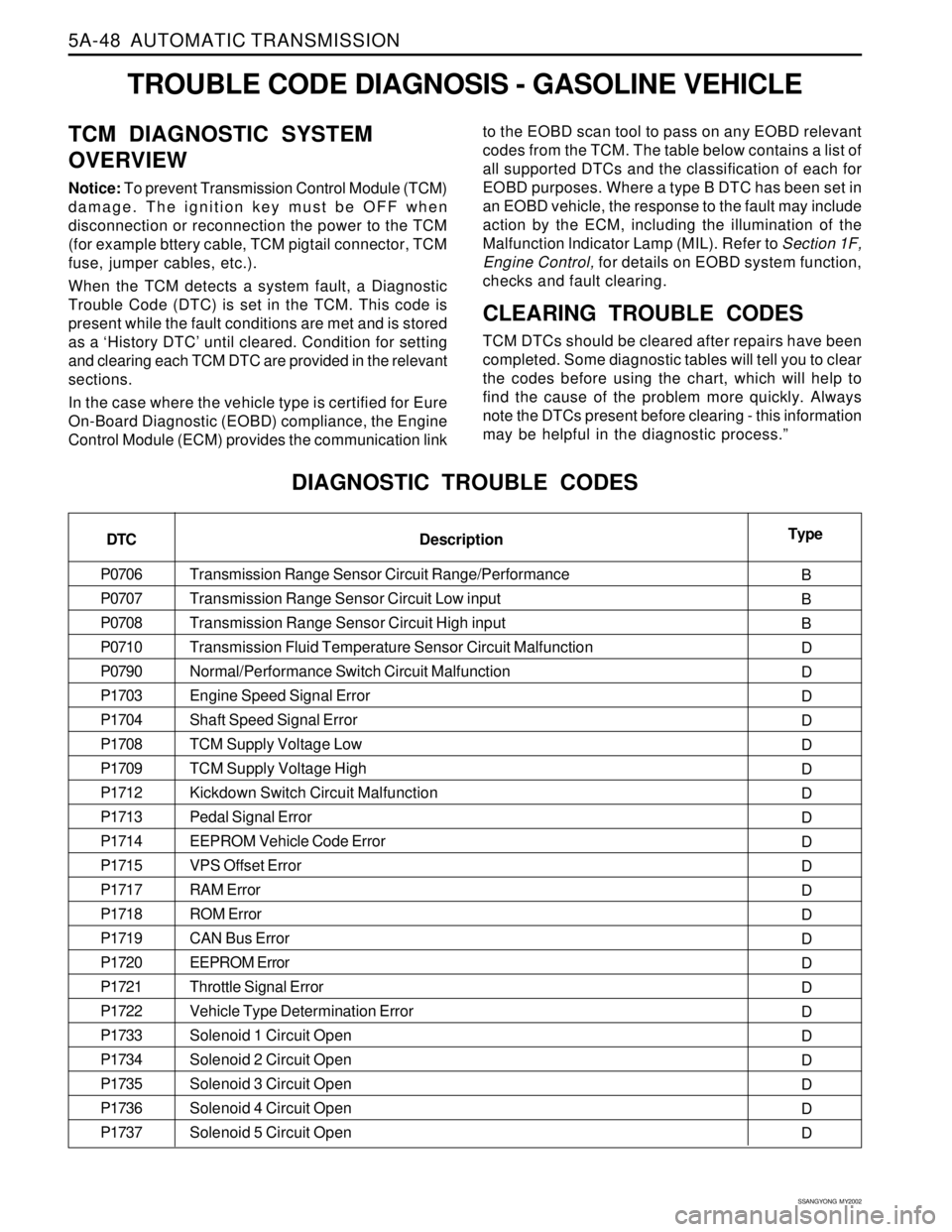
TROUBLE CODE DIAGNOSIS - GASOLINE VEHICLE
TCM DIAGNOSTIC SYSTEM
OVERVIEW
Notice: To prevent Transmission Control Module (TCM)
damage. The ignition key must be OFF when
disconnection or reconnection the power to the TCM
(for example bttery cable, TCM pigtail connector, TCM
fuse, jumper cables, etc.).
When the TCM detects a system fault, a Diagnostic
Trouble Code (DTC) is set in the TCM. This code is
present while the fault conditions are met and is stored
as a ‘History DTC’ until cleared. Condition for setting
and clearing each TCM DTC are provided in the relevant
sections.
In the case where the vehicle type is certified for Eure
On-Board Diagnostic (EOBD) compliance, the Engine
Control Module (ECM) provides the communication linkto the EOBD scan tool to pass on any EOBD relevant
codes from the TCM. The table below contains a list of
all supported DTCs and the classification of each for
EOBD purposes. Where a type B DTC has been set in
an EOBD vehicle, the response to the fault may include
action by the ECM, including the illumination of the
Malfunction lndicator Lamp (MIL). Refer to Section 1F,
Engine Control, for details on EOBD system function,
checks and fault clearing.
CLEARING TROUBLE CODES
TCM DTCs should be cleared after repairs have been
completed. Some diagnostic tables will tell you to clear
the codes before using the chart, which will help to
find the cause of the problem more quickly. Always
note the DTCs present before clearing - this information
may be helpful in the diagnostic process.”
DIAGNOSTIC TROUBLE CODES
DTC
P0706
P0707
P0708
P0710
P0790
P1703
P1704
P1708
P1709
P1712
P1713
P1714
P1715
P1717
P1718
P1719
P1720
P1721
P1722
P1733
P1734
P1735
P1736
P1737Type
B
B
B
D
D
D
D
D
D
D
D
D
D
D
D
D
D
D
D
D
D
D
D
D Description
Transmission Range Sensor Circuit Range/Performance
Transmission Range Sensor Circuit Low input
Transmission Range Sensor Circuit High input
Transmission Fluid Temperature Sensor Circuit Malfunction
Normal/Performance Switch Circuit Malfunction
Engine Speed Signal Error
Shaft Speed Signal Error
TCM Supply Voltage Low
TCM Supply Voltage High
Kickdown Switch Circuit Malfunction
Pedal Signal Error
EEPROM Vehicle Code Error
VPS Offset Error
RAM Error
ROM Error
CAN Bus Error
EEPROM Error
Throttle Signal Error
Vehicle Type Determination Error
Solenoid 1 Circuit Open
Solenoid 2 Circuit Open
Solenoid 3 Circuit Open
Solenoid 4 Circuit Open
Solenoid 5 Circuit Open
Page 1145 of 2053

5A-50 AUTOMATIC TRANSMISSION
SSANGYONG MY2002
Transmission Range Sensor Circuit Low Input
Transmission Range Sensor Circuit High Input
Transmission Fluid Temperature Sensor Circuit Malfunction
Normal/Performance Switch Circuit Malfunction
Engine Speed Signal Error
Shaft Speed Signal Error
TCM Supply Voltage Low
TCM Supply Voltage High
Air Conditioning Switch Circuit Malfunction
Kickdown Switch Circuit Malfunction
EEPROM Vehicle Code Error
VPS Offset Error
Throttle Not Learnt Error
RAM Error
ROM Error
EEPROM Error
Throttle Signal Error
Vehicle Type Determination Error
Solenoid 1 Circuit Open
Solenoid 2 Circuit Open
Solenoid 3 Circuit Open
Solenoid 4 Circuit Open
Solenoid 5 Circuit Open
Solenoid 6 Circuit Open
Solenoid 7 Circuit Open
Solenoid 1 Circuit Short
Solenoid 2 Circuit Short
Solenoid 3 Circuit Short
Solenoid 4 Circuit Short
TROUBLE CODE DIAGNOSIS - DIESEL VEHICLE
TCM DIAGNOSTIC SYSTEM
OVERVIEW
Notice: To prevent Transmission Control Module (TCM)
damage. The ignition key must be OFF when
disconnection or reconnection the power to the TCM
(for example bttery cable, TCM pigtail connector, TCM
fuse, jumper cables, etc.).
When the TCM detects a system fault, a Diagnostic
Trouble Code (DTC) is set in the TCM. This code is
present while the fault conditions are met and is storedas a ‘History DTC’ until cleared. Condition for setting
and clearing each TCM DTC are provided in the relevant
sections.CLEARING TROUBLE CODES
TCM DTCs should be cleared after repairs have been
completed. Some diagnostic tables will tell you to clear
the codes before using the chart, which will help to
find the cause of the problem more quickly. Always
note the DTCs present before clearing - this information
may be helpful in the diagnostic process.
DIAGNOSTIC TROUBLE CODES
DTC
P0707
P0708
P0710
P0790
P1703
P1704
P1708
P1709
P1710
P1712
P1714
P1715
P1716
P1717
P1718
P1720
P1721
P1722
P1733
P1734
P1735
P1736
P1737
P1738
P1739
P1741
P1742
P1743
P1744Description
Page 1292 of 2053

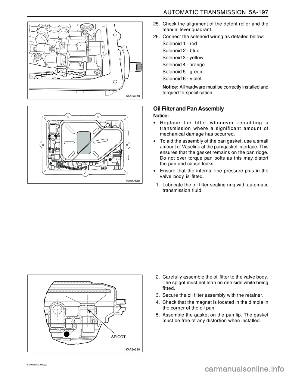
AUTOMATIC TRANSMISSION 5A-197
SSANGYONG MY2002
2. Carefully assemble the oil filter to the valve body.
The spigot must not lean on one side while being
fitted.
3. Secure the oil filter assembly with the retainer.
4. Check that the magnet is located in the dimple in
the corner of the oil pan.
5. Assemble the gasket on the pan lip. The gasket
must be free of any distortion when installed. 25. Check the alignment of the detent roller and the
manual lever quadrant.
26. Connect the solenoid wiring as detailed below:
Solenoid 1 - red
Solenoid 2 - bIue
Solenoid 3 - yellow
Solenoid 4 - orange
Solenoid 5 - green
Solenoid 6 - violet
Notice: All hardware must be correctly installed and
torqued to specification.
Oil Filter and Pan Assembly
Notice:
Replace the filter whenever rebuilding a
transmission where a significant amount of
mechanical damage has occurred.
To aid the assembly of the pan gasket, use a small
amount of Vaseline at the pan/gasket interface. This
ensures that the gasket remains on the pan ridge.
Do not over torque pan bolts as this may distort
the pan and cause leaks.
Ensure that the internal line pressure plus in the
valve body is fitted.
1. Lubricate the oil filter sealing ring with automatic
transmission fluid.
KAA5A2B0 KAA5A2A0
KAA5A510