SSANGYONG KORANDO 1997 Service Repair Manual
KORANDO 1997
SSANGYONG
SSANGYONG
https://www.carmanualsonline.info/img/67/57502/w960_57502-0.png
SSANGYONG KORANDO 1997 Service Repair Manual
Page 11 of 2053

GENERAL INFORMATION 0B -- 11
D AEW OO M Y_2000
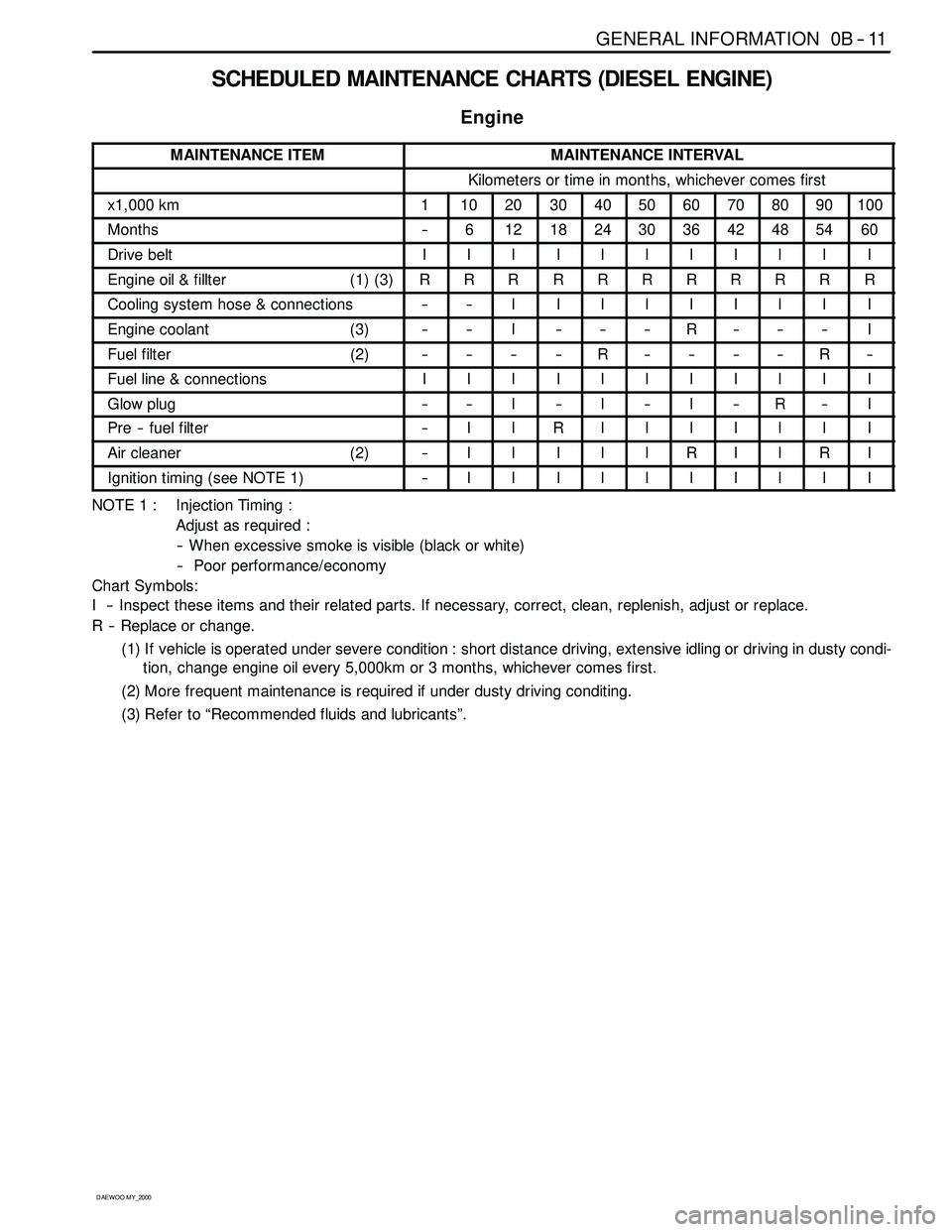
SCHEDULED MAINTENANCE CHARTS (DIESEL ENGINE)
Engine
MAINTENANCE ITEMMAINTENANCE INTERVAL
Kilometers or time in months, whichever comes first
x1,000 km1102030405060708090100
Months--6121824303642485460
Drive beltIIIIIIIIIII
Engine oil & fillter (1) (3)RRRRRRRRRRR
Cooling system hose & connections----IIIIIIIII
Engine coolant (3)----I------R------I
Fuel filter (2)--------R--------R--
Fuel line & connectionsIIIIIIIIIII
Glow plug----I--I--I--R--I
Pre -- fuel filter--IIRIIIIIII
Air cleaner (2)--IIIIIRIIRI
Ignition timing (see NOTE 1)--IIIIIIIIII
NOTE 1 : Injection Timing :
Adjust as required :
-- When excessive smoke is visible (black or white)
-- Poor performance/economy
Chart Symbols:
I -- Inspect these items and their related parts. If necessary, correct, clean, replenish, adjust or replace.
R -- Replace or change.
(1) If vehicle is operated under severe condition : short distance driving, extensive idling or driving in dusty condi-
tion, change engine oil every 5,000km or 3 months, whichever comes first.
(2) More frequent maintenance is required if under dusty driving conditing.
(3) Refer to “Recommended fluids and lubricants”.
Page 578 of 2053
OM600 ENGINE MECHANICAL 1B3 -- 29
D AEW OO M Y_2000
PRECHAMBER
Preceding Work : Removal of glow plug
Removal of fuel injection nozzle
1 Threaded Ring 130 N∙m (96 lb-ft) ...........
2 Prechamber3 Cylinder Head
Page 592 of 2053
OM600 ENGINE MECHANICAL 1B3 -- 43
D AEW OO M Y_2000
18. Disconnect the booster hose connected to intake
manifold.
19. Remove the intake manifold and gasket.
20. Remove the cylinder head cover and gasket with the
blow-- by gas hose.
21. Disconnect the glow plug cables.
Page 593 of 2053
1B3 -- 44 OM600 ENGINE MECHANICAL
D AEW OO M Y_2000
22. Remove the cable channel.
23 .Disconnect the cables from the glow plug sensor
and coolant temperature sensor.
24. Remove the heater pipe bracket from the oil filter.
25. Pry off the clamp and push the heater feed pipe for-
ward and then pull out the pipe.
Page 608 of 2053
OM600 ENGINE MECHANICAL 1B3 -- 59
D AEW OO M Y_2000
27. Replace the seal and then install the chain tension-
er.
Tightening Torque80 N∙m (59 lb-ft)
28. Remove the engine lock.
29. Insert the nozzle washer into the hole to face round
part downward.
30. Install the fuel injection nozzle.
Tightening Torque40 N∙m (30 lb-ft)
31. Connect the fuel hose.
32. Install the cable channel and connect the cables to
glow plugs.
Page 609 of 2053
1B3 -- 60 OM600 ENGINE MECHANICAL
D AEW OO M Y_2000
33. Replace the gasket and install the cylinder head
cover.
Tightening Torque10 N∙m(89lb-in)
34. Install the blow-- by hose.
35. Connect the wires to the coolant temperature sen-
sor and the glow plug sensor.
36. Replace the intake manifold gasket.
37. Install the intake manifold.
Tightening Torque25 N∙m (18 lb-ft)
Page 686 of 2053
OM600 ENGINE MECHANICAL 1B3 -- 137
D AEW OO M Y_2000
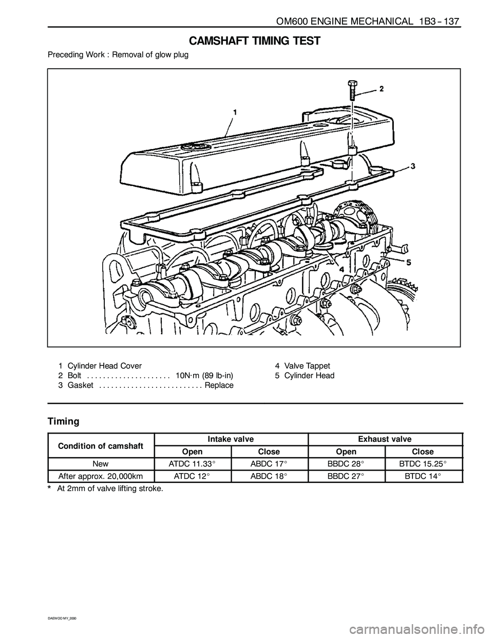
CAMSHAFT TIMING TEST
Preceding Work : Removal of glow plug
1 Cylinder Head Cover
2 Bolt 10N∙m (89 lb-in) .....................
3 Gasket Replace..........................4 Valve Tappet
5 Cylinder Head
Timing
CditifhftIntake valveExhaust valveCondition of camshaftOpenCloseOpenClose
NewAT DC 11 . 3 3_ABDC 17_BBDC 28_BTDC 15.25_
After approx. 20,000kmAT DC 1 2_ABDC 18_BBDC 27_BTDC 14_
* At 2mm of valve lifting stroke.
Page 696 of 2053
OM600 ENGINE MECHANICAL 1B3 -- 147
D AEW OO M Y_2000
TIMING CHAIN
Preceding Work : Removal of glow plug
Removal of chain tensioner
Removal of cooling fan
Removal of cylinder head cover
1 Chain Link
2 Timing Chain
3 Camshaft Sprocket
4 Outer Plate
Page 753 of 2053
D AEW OO M Y_2000
SECTION 1E3
OM600 ENGINE ELECTRICAL
Caution: Disconnect the negative battery cable before removing or installing any electrical unit or when a
tool or equipment could easily come in contact with exposed electrical terminals. Disconnecting this cable
will help prevent personal injury and damage to the vehicle. The ignition must also be in LOCK unless other -
wise noted.
TABLE OF CONTENTS
Specifications 1E3 -- 1............................
General Specifications 1E3-- 1....................
Maintenance and Repair 1E3 -- 2...................
On-- Vehicle Service 1E3-- 2.........................Glow Plug 1E3-- 2...............................
Generator 1E3-- 6...............................
Starter Motor 1E3-- 8............................
SPECIFICATIONS
GENERAL SPECIFICATIONS
ApplicationDescription
Generator12V -- 75A
Starter12V -- 2.2kW
Glow Plug11. 5 V
Page 924 of 2053
SSAMGYONG MY2002
4A-4 HYDRAULIC BRAKES
KAA4A010
BRAKE WARNING LAMP CIRCUIT DESCRIPTION
Diagnostic Aids
The BRAKE lamp glows brightly when the ignition is
ON and either the parking brake lever switch or the
brake fluid level switch is closed.
If neither switch is closed, the BRAKE lamp receives
a ground through the generator, and it glows dimly
when the ignition is ON and the engine is off. When
the engine starts, the generator creates voltage. With
voltage on both sides of the lamp, the lamp turns off.
Test Description
The numbers below refer to steps in the diagnostic
table.
1. This step begins the test sequence for a BRAKE
warning lamp that stays on when the engine is run-
ning.
2. This step begins the test sequence for a BRAKE
warning lamp that never turns on.


