transfer case SSANGYONG KORANDO 1997 Service Repair Manual
[x] Cancel search | Manufacturer: SSANGYONG, Model Year: 1997, Model line: KORANDO, Model: SSANGYONG KORANDO 1997Pages: 2053, PDF Size: 88.33 MB
Page 10 of 2053
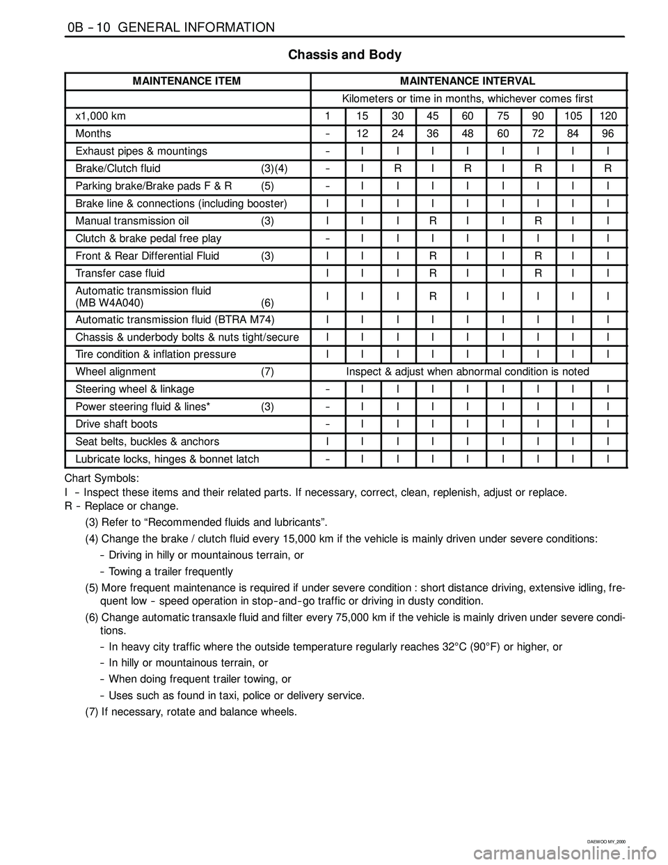
0B -- 10 GENERAL INFORMATION
D AEW OO M Y_2000
Chassis and Body
MAINTENANCE ITEMMAINTENANCE INTERVAL
Kilometers or time in months, whichever comes first
x1,000 km1153045607590105120
Months--1224364860728496
Exhaust pipes & mountings--IIIIIIII
Brake/Clutch fluid (3)(4)--IRIRIRIR
Parking brake/Brake pads F & R (5)--IIIIIIII
Brake line & connections (including booster)IIIIIIIII
Manual transmission oil (3)IIIRIIRII
Clutch & brake pedal free play--IIIIIIII
Front & Rear Differential Fluid (3)IIIRIIRII
Transfer case fluidIIIRIIRII
Automatic transmission fluid
(MB W4A040) (6)IIIRIIIII
Automatic transmission fluid (BTRA M74)IIIIIIIII
Chassis & underbody bolts & nuts tight/secureIIIIIIIII
Tire condition & inflation pressureIIIIIIIII
Wheel alignment (7)Inspect & adjust when abnormal condition is noted
Steering wheel & linkage--IIIIIIII
Power steering fluid & lines* (3)--IIIIIIII
Drive shaft boots--IIIIIIII
Seat belts, buckles & anchorsIIIIIIIII
Lubricate locks, hinges & bonnet latch--IIIIIIII
Chart Symbols:
I -- Inspect these items and their related parts. If necessary, correct, clean, replenish, adjust or replace.
R -- Replace or change.
(3) Refer to “Recommended fluids and lubricants”.
(4) Change the brake / clutch fluid every 15,000 km if the vehicle is mainly driven under severe conditions:
-- Driving in hilly or mountainous terrain, or
-- Towing a trailer frequently
(5) More frequent maintenance is required if under severe condition : short distance driving, extensive idling, fre-
quent low -- speed operation in stop-- and-- go traffic or driving in dusty condition.
(6) Change automatic transaxle fluid and filter every 75,000 km if the vehicle is mainly driven under severe condi-
tions.
-- In heavy city traffic where the outside temperature regularly reaches 32°C(90°F) or higher, or
-- In hilly or mountainous terrain, or
-- When doing frequent trailer towing, or
-- Uses such as found in taxi, police or delivery service.
(7) If necessary, rotate and balance wheels.
Page 12 of 2053
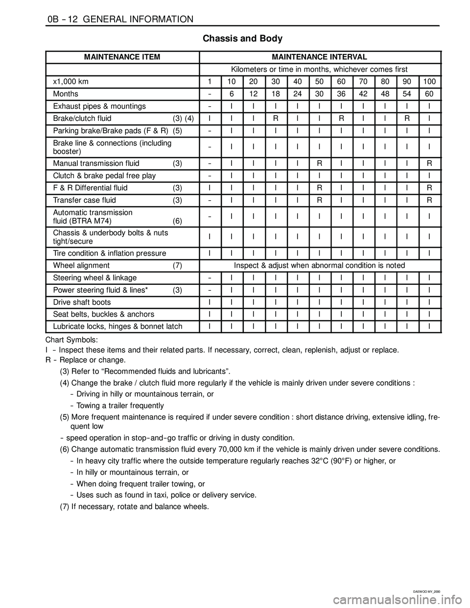
0B -- 12 GENERAL INFORMATION
D AEW OO M Y_2000
Chassis and Body
MAINTENANCE ITEMMAINTENANCE INTERVAL
Kilometers or time in months, whichever comes first
x1,000 km1102030405060708090100
Months--6121824303642485460
Exhaust pipes & mountings--IIIIIIIIII
Brake/clutch fluid (3) (4)IIIRIIRIIRI
Parking brake/Brake pads (F & R) (5)--IIIIIIIIII
Brake line & connections (including
booster)--IIIIIIIIII
Manual transmission fluid (3)--IIIIRIIIIR
Clutch & brake pedal free play--IIIIIIIIII
F & R Differential fluid (3)IIIIIRIIIIR
Transfer case fluid (3)--IIIIRIIIIR
Automatic transmission
fluid (BTRA M74) (6)--IIIIIIIIII
Chassis & underbody bolts & nuts
tight/secureIIIIIIIIIII
Tire condition & inflation pressureIIIIIIIIIII
Wheel alignment (7)Inspect & adjust when abnormal condition is noted
Steering wheel & linkage--IIIIIIIIII
Power steering fluid & lines* (3)--IIIIIIIIII
Drive shaft bootsIIIIIIIIIII
Seat belts, buckles & anchorsIIIIIIIIIII
Lubricate locks, hinges & bonnet latchIIIIIIIIIII
Chart Symbols:
I -- Inspect these items and their related parts. If necessary, correct, clean, replenish, adjust or replace.
R -- Replace or change.
(3) Refer to “Recommended fluids and lubricants”.
(4) Change the brake / clutch fluid more regularly if the vehicle is mainly driven under severe conditions :
-- Driving in hilly or mountainous terrain, or
-- Towing a trailer frequently
(5) More frequent maintenance is required if under severe condition : short distance driving, extensive idling, fre-
quent low
-- speed operation in stop-- and-- go traffic or driving in dusty condition.
(6) Change automatic transmission fluid every 70,000 km if the vehicle is mainly driven under severe conditions.
-- In heavy city traffic where the outside temperature regularly reaches 32°C(90°F) or higher, or
-- In hilly or mountainous terrain, or
-- When doing frequent trailer towing, or
-- Uses such as found in taxi, police or delivery service.
(7) If necessary, rotate and balance wheels.
Page 252 of 2053
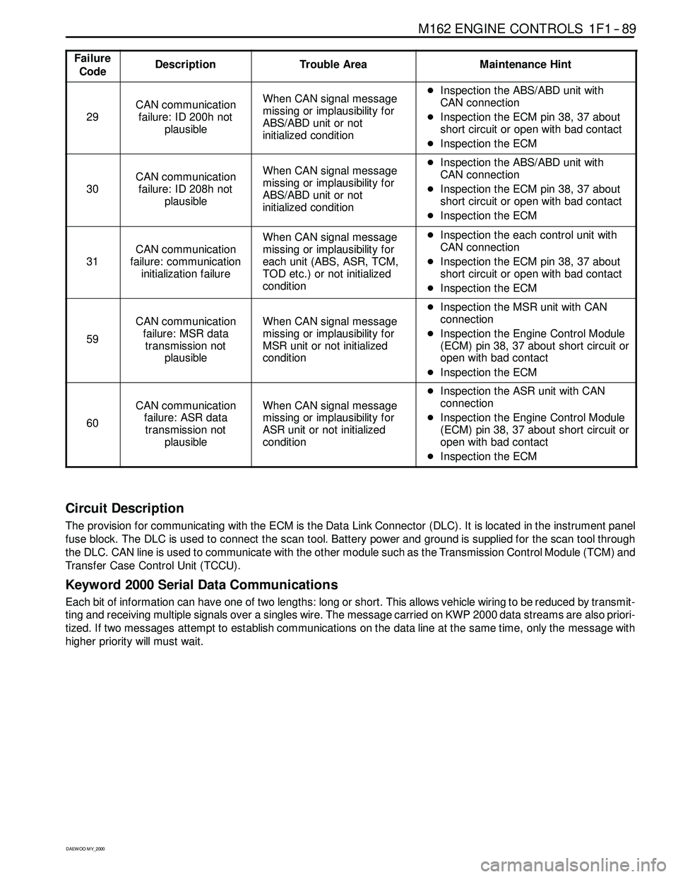
M162 ENGINE CONTROLS 1F1 -- 89
D AEW OO M Y_2000
Failure
CodeDescriptionTrouble AreaMaintenance Hint
29
CAN communication
failure: ID 200h not
plausibleWhen CAN signal message
missing or implausibility for
ABS/ABD unit or not
initialized conditionDInspection the ABS/ABD unit with
CAN connection
DInspection the ECM pin 38, 37 about
short circuit or open with bad contact
DInspection the ECM
30
CAN communication
failure: ID 208h not
plausibleWhen CAN signal message
missing or implausibility for
ABS/ABD unit or not
initialized conditionDInspection the ABS/ABD unit with
CAN connection
DInspection the ECM pin 38, 37 about
short circuit or open with bad contact
DInspection the ECM
31
CAN communication
failure: communication
initialization failure
When CAN signal message
missing or implausibility for
each unit (ABS, ASR, TCM,
TOD etc.) or not initialized
conditionDInspection the each control unit with
CAN connection
DInspection the ECM pin 38, 37 about
short circuit or open with bad contact
DInspection the ECM
59
CAN communication
failure: MSR data
transmission not
plausibleWhen CAN signal message
missing or implausibility for
MSR unit or not initialized
condition
DInspection the MSR unit with CAN
connection
DInspection the Engine Control Module
(ECM) pin 38, 37 about short circuit or
open with bad contact
DInspection the ECM
60
CAN communication
failure: ASR data
transmission not
plausibleWhen CAN signal message
missing or implausibility for
ASR unit or not initialized
condition
DInspection the ASR unit with CAN
connection
DInspection the Engine Control Module
(ECM) pin 38, 37 about short circuit or
open with bad contact
DInspection the ECM
Circuit Description
The provision for communicating with the ECM is the Data Link Connector (DLC). It is located in the instrument panel
fuse block. The DLC is used to connect the scan tool. Battery power and ground is supplied for the scan tool through
the DLC. CAN line is used to communicate with the other module such as the Transmission Control Module (TCM) and
Transfer Case Control Unit (TCCU).
Keyword 2000 Serial Data Communications
Each bit of information can have one of two lengths: long or short. This allows vehicle wiring to be reduced by transmit-
ting and receiving multiple signals over a singles wire. The message carried on KWP 2000 data streams are also priori-
tized. If two messages attempt to establish communications on the data line at the same time, only the message with
higher prioritywill must wait.
Page 507 of 2053
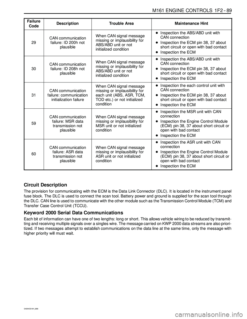
M161 ENGINE CONTROLS 1F2 -- 89
D AEW OO M Y_2000
Failure
CodeDescriptionTrouble AreaMaintenance Hint
29
CAN communication
failure: ID 200h not
plausibleWhen CAN signal message
missing or implausibility for
ABS/ABD unit or not
initialized conditionDInspection the ABS/ABD unit with
CAN connection
DInspection the ECM pin 38, 37 about
short circuit or open with bad contact
DInspection the ECM
30
CAN communication
failure: ID 208h not
plausibleWhen CAN signal message
missing or implausibility for
ABS/ABD unit or not
initialized conditionDInspection the ABS/ABD unit with
CAN connection
DInspection the ECM pin 38, 37 about
short circuit or open with bad contact
DInspection the ECM
31
CAN communication
failure: communication
initialization failure
When CAN signal message
missing or implausibility for
each unit (ABS, ASR, TCM,
TOD etc.) or not initialized
conditionDInspection the each control unit with
CAN connection
DInspection the ECM pin 38, 37 about
short circuit or open with bad contact
DInspection the ECM
59
CAN communication
failure: MSR data
transmission not
plausibleWhen CAN signal message
missing or implausibility for
MSR unit or not initialized
condition
DInspection the MSR unit with CAN
connection
DInspection the Engine Control Module
(ECM) pin 38, 37 about short circuit or
open with bad contact
DInspection the ECM
60
CAN communication
failure: ASR data
transmission not
plausibleWhen CAN signal message
missing or implausibility for
ASR unit or not initialized
condition
DInspection the ASR unit with CAN
connection
DInspection the Engine Control Module
(ECM) pin 38, 37 about short circuit or
open with bad contact
DInspection the ECM
Circuit Description
The provision for communicating with the ECM is the Data Link Connector (DLC). It is located in the instrument panel
fuse block. The DLC is used to connect the scan tool. Battery power and ground is supplied for the scan tool through
the DLC. CAN line is used to communicate with the other module such as the Transmission Control Module (TCM) and
Transfer Case Control Unit (TCCU).
Keyword 2000 Serial Data Communications
Each bit of information can have one of two lengths: long or short. This allows vehicle wiring to be reduced by transmit-
ting and receiving multiple signals over a singles wire. The message carried on KWP 2000 data streams are also priori-
tized. If two messages attempt to establish communications on the data line at the same time, only the message with
higher prioritywill must wait.
Page 871 of 2053
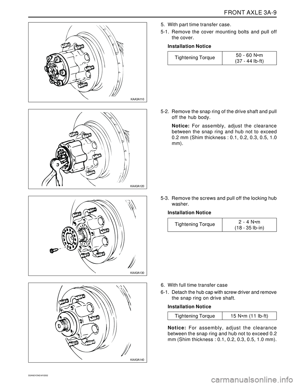
FRONT AXLE 3A-9
SSANGYONG MY2002
5. With part time transfer case.
5-1.Remove the cover mounting bolts and pull off
the cover.
Installation Notice
5-2. Remove the snap ring of the drive shaft and pull
off the hub body.
Notice: For assembly, adjust the clearance
between the snap ring and hub not to exceed
0.2 mm (Shim thickness : 0.1, 0.2, 0.3, 0.5, 1.0
mm).
6. With full time transfer case
6-1. Detach the hub cap with screw driver and remove
the snap ring on drive shaft.
Installation Notice 5-3.Remove the screws and pull off the locking hub
washer.
Installation Notice
Notice: For assembly, adjust the clearance
between the snap ring and hub not to exceed 0.2
mm (Shim thickness : 0.1, 0.2, 0.3, 0.5, 1.0 mm).
KAA3A110
KAA3A120
KAA3A130
KAA3A140
Tightening Torque50 - 60 Nm
(37 - 44 lb-ft)
Tightening Torque2 - 4 Nm
(18 - 35 lb-in)
Tightening Torque 15 Nm (11 lb-ft)
Page 891 of 2053
SSANGYONG MY2002
3C-4 PROPELLER SHAFT
KAA3C070
KAA3C080
KAA3C060
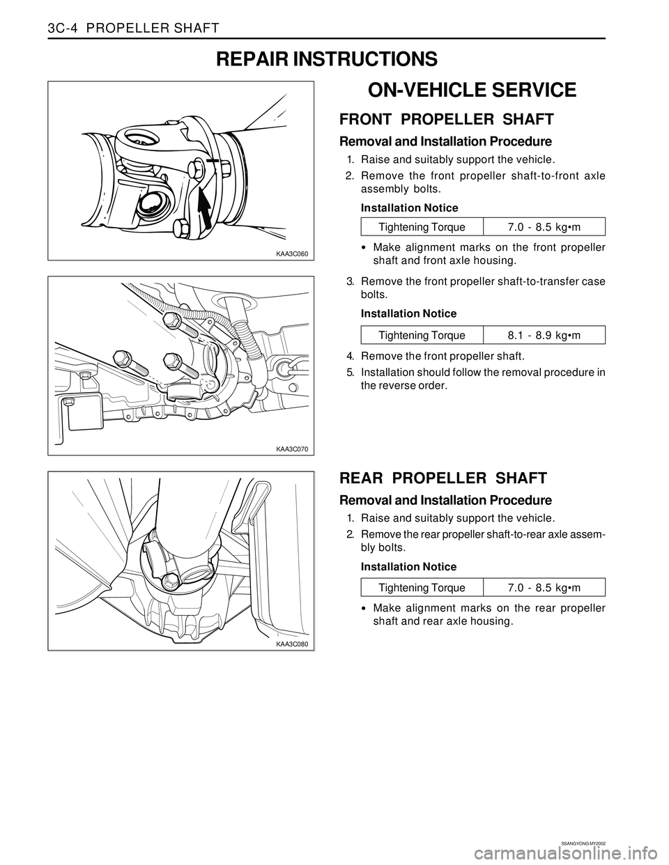
ON-VEHICLE SERVICE
FRONT PROPELLER SHAFT
Removal and Installation Procedure
1. Raise and suitably support the vehicle.
2. Remove the front propeller shaft-to-front axle
assembly bolts.
Installation Notice
REPAIR INSTRUCTIONS
Tightening Torque7.0 - 8.5 kgm
Make alignment marks on the front propeller
shaft and front axle housing.
3. Remove the front propeller shaft-to-transfer case
bolts.
Installation Notice
Tightening Torque8.1 - 8.9 kgm
4. Remove the front propeller shaft.
5. Installation should follow the removal procedure in
the reverse order.
REAR PROPELLER SHAFT
Removal and Installation Procedure
1. Raise and suitably support the vehicle.
2. Remove the rear propeller shaft-to-rear axle assem-
bly bolts.
Installation Notice
Tightening Torque7.0 - 8.5 kgm
Make alignment marks on the rear propeller
shaft and rear axle housing.
Page 892 of 2053
PROPELLER SHAFT 3C-5
SSANGYONG MY2002
KAA3C090
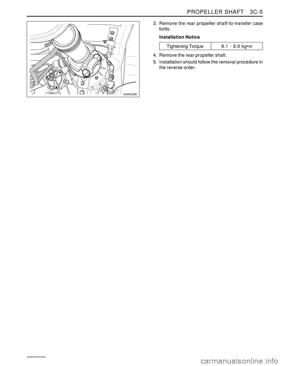
3. Remove the rear propeller shaft-to-transfer case
bolts.
Installation Notice
Tightening Torque8.1 - 8.9 kgm
4. Remove the rear propeller shaft.
5. Installation should follow the removal procedure in
the reverse order.
Page 1096 of 2053
5A-2 AUTOMATIC TRANSMISSION
SSANGYONG MY2002
OPERATORS INTERFACES
There are three operator interfaces as the following;
•Gear Shift Control Lever
Driving Mode Selector
Indicator Light
Gear Shift Control lever
The transmission uses a conventional shift control lever.
The gear shift control lever can be moved from one
position to another within the staggered configuration
of the shift control lever gate to positively indicate the
gear selection.
DESCRIPTION AND OPERATION
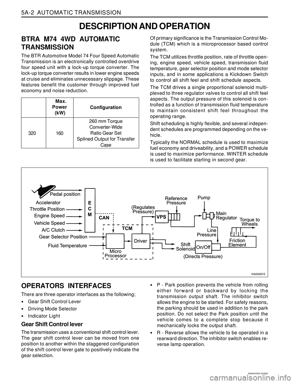
BTRA M74 4WD AUTOMATIC
TRANSMISSION
The BTR Automotive Model 74 Four Speed Automatic
Transmission is an electronically controlled overdrive
four speed unit with a lock-up torque converter. The
lock-up torque converter results in lower engine speeds
at cruise and eliminates unnecessary slippage. These
features benefit the customer through improved fuel
economy and noise reduction.Of primary significance is the Transmission Control Mo-
dule (TCM) which is a microprocessor based control
system.
The TCM utilizes throttle position, rate of throttle open-
ing, engine speed, vehicle speed, transmission fluid
temperature, gear selector position and mode selector
inputs, and in some applications a Kickdown Switch
to control all shift feel and shift schedule aspects.
The TCM drives a single proportional solenoid multi-
plexed to three regulator valves to control all shift feel
aspects. The output pressure of this solenoid is con-
trolled as a function of transmission fluid temperature
to maintain consistent shift feel throughout the
operating range.
Shift scheduling is highly flexible, and several indepen-
dent schedules are programmed depending on the ve-
hicle.
Typically the NORMAL schedule is used to maximize
fuel economy and driveability, and a POWER schedule
is used to maximize performance. WINTER schedule
is used to facilitate starting in second gear. Configuration Max.
Power
(kW)
320 160260 mm Torque
Converter-Wide
Ratio Gear Set
Splined Output for Transfer
Case
P - Park position prevents the vehicle from rolling
either forward or backward by locking the
transmission output shaft. The inhibitor switch
allows the engine to be started. For safety reasons,
the parking should be used in addition to the park
position. Do not select the Park position until the
vehicle comes to a complete stop because it
mechanically locks the output shaft.
R - Reverse allows the vehicle to be operated in a
rearward direction. The inhibitor switch enables re-
verse lamp operation.
KAA5A010
Page 1099 of 2053
AUTOMATIC TRANSMISSION 5A-5
SSANGYONG MY2002
Engine Speed
The engine speed signal is derived from the Control-
ler Area Network (CAN) via Engine Control Module
(ECM).
Vehicle Speed
The vehicle speed sensor, which is located in the
transfer case, sends the output shaft speed signal
to the Engine Control Module (ECM). The information
is then transferred to the TCM via the CAN.
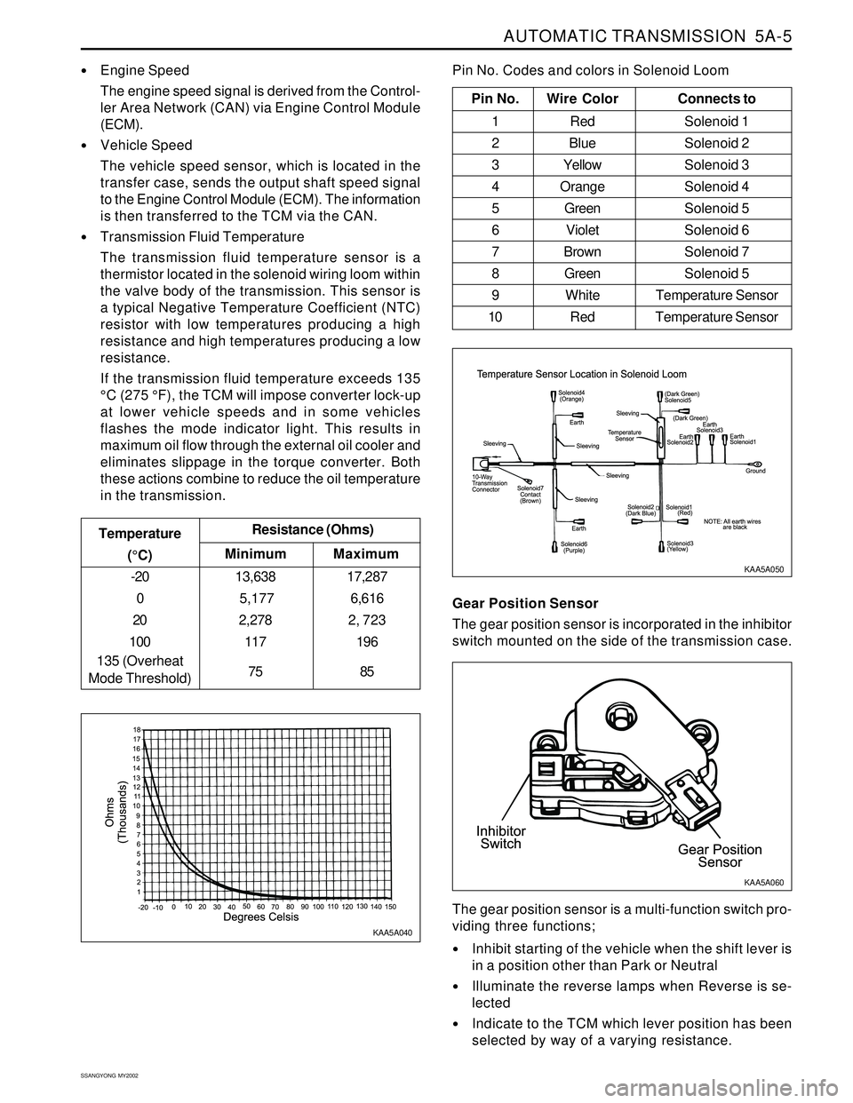
Transmission Fluid Temperature
The transmission fluid temperature sensor is a
thermistor located in the solenoid wiring loom within
the valve body of the transmission. This sensor is
a typical Negative Temperature Coefficient (NTC)
resistor with low temperatures producing a high
resistance and high temperatures producing a low
resistance.
If the transmission fluid temperature exceeds 135
°C (275 °F), the TCM will impose converter lock-up
at lower vehicle speeds and in some vehicles
flashes the mode indicator light. This results in
maximum oil flow through the external oil cooler and
eliminates slippage in the torque converter. Both
these actions combine to reduce the oil temperature
in the transmission.
Minimum Temperature
(°C)Resistance (Ohms)
-20
0
20
100
135 (Overheat
Mode Threshold)13,638
5,177
2,278
117
75
Maximum
17,287
6,616
2, 723
196
85
Pin No. Wire ColorConnects to
1 Red Solenoid 1
2 BlueSolenoid 2
3 YellowSolenoid 3
4 OrangeSolenoid 4
5 GreenSolenoid 5
6 VioletSolenoid 6
7 BrownSolenoid 7
8 GreenSolenoid 5
9 White Temperature Sensor
10 Red Temperature Sensor
Pin No. Codes and colors in Solenoid Loom
KAA5A040KAA5A050
Gear Position Sensor
The gear position sensor is incorporated in the inhibitor
switch mounted on the side of the transmission case.
Inhibit starting of the vehicle when the shift lever is
in a position other than Park or Neutral
Illuminate the reverse lamps when Reverse is se-
lected
Indicate to the TCM which lever position has been
selected by way of a varying resistance. The gear position sensor is a multi-function switch pro-
viding three functions;
KAA5A060
Page 1245 of 2053
AUTOMATIC TRANSMISSION 5A-157
SSANGYONG MY2002
ON-VEHICLE SERVICE
TRANSMISSION
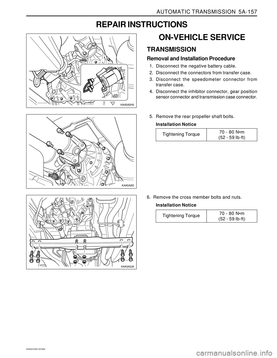
Removal and Installation Procedure
1. Disconnect the negative battery cable.
2. Disconnect the connectors from transfer case.
3. Disconnect the speedometer connector from
transfer case.
4. Disconnect the inhibitor connector, gear position
sensor connector and transmission case connector.
REPAIR INSTRUCTIONS
5. Remove the rear propeller shaft bolts.
Installation Notice
6. Remove the cross member bolts and nuts.
Installation Notice
KAA5A2I0
Tightening Torque70 - 80 N•m
(52 - 59 lb-ft)
Tightening Torque70 - 80 Nm
(52 - 59 lb-ft)
KAA5A2H0
KAA5A2J0